Ray
COVEY
Vaporizer / Carburetor
Vaporizer / Carburetor
http://fuel-efficient-vehicles.org/energy-news/?page_id=941
Ray Covey of El Paso, TX – worked on a high mileage carburetor modeled after a Sgrignoli design for over a year, and ended up getting 65 MPG on his Chrysler V-8… With an occasional 100 MPG… After applying for a patent, Covey began marketing plans to his device and installed several units for a few of his customers… Covey built another design similar to a Ford Motor Company patent and started marketing plans to the new design too…
https://www.amazon.com/Ray-Coveys-vapor-carburetor-system/dp/B0006YKW4Y
http://www.worldcat.org/title/ray-coveys-vapor-or-carburetor-system-the-complete-working-plans/oclc/317422568/editions?referer=di&editionsView=true
Ray
Covey's vapor or carburetor system: The complete working
plans 1982
by Ray M. Covey
by Ray M. Covey
36 pages : illustrations

http://www.keelynet.com/energy/gunnhist.htm
Parascience #2, Winter,1998
A History of Vapor Carburetors
by Robert Felix
by Robert Felix
... The inventor Ray Covey solved the problem by leaving the conventional carburetor attached to the engine and placing the vaporizer in series with it connected by a heat insulated tube. The engine could be started from the regular carburetor and then switched over to vapor mode once the heat exchanger had reached the proper temperature by use of a two way electric solenoid switch in series with the carburetor fuel line...
Weld a catalytic converter in series between the exhaust manifold of the gasoline engine and the exhaust input to the heat exchanger/vaporizer that is described in the patents cited. The catalytic converter acts as a heat amplifier and its output is at a much higher temperature than its input.
The thermal conductivity of steel is lower than that of copper or brass, but this will compensate. Ray Covey (USP #4611567) used this with his system, as building a heat exchanger of 1/8 or 1/4 inch dia. brass plate is very expensive...
Other patents cited here may or may not run on the principle of thermo catalytic cracking of gasoline, (pyrolysis) or the inventors might have hidden this information in the patent application for legal reasons.
The late Ray Covey (US Patent 4611567) observed this process in his device but was unaware of exactly what was happening - more than just vaporization of the fractions of gasoline was occurring...
Vaporizer/carburetor
and method
US4883616
US4883616
A vaporizer unit has an enclosing casing including a plurality of tubes therein, defining a fuel passage therethrough, including the tubes. The tubes have coiled wire screen therein. An auxiliary carburetor is positioned at the inlet end of the fuel passage, and an outlet passage leads to the main carburetor of the automobile. The casing also defines an exhaust passage therethrough, transversely of the fuel passage, providing heat transfer between the exhaust gases and the tubes. The temperature of the resulting vaporized fuel is sensed for varying the flow of the exhaust gases and thereby controlling the temperature of the vaporized fuel, which is maintained at 250 DEG F. to 260 DEG F. An electric crystal is used for breaking down the heavy ends of the fuel. The rate of flow of air to the main carburetor is varied for correspondingly varying the rate of intake of vaporized fuel from the vaporizer unit. Automatic and manual controls are both utilized selectively, each without interfering with the other.
FIELD OF THE INVENTION
The invention resides in the general field of vaporizing liquid petroleum fuel for internal combustion engines, the most common example of which is in the case of automobiles.
OBJECTS OF THE INVENTION
A broad object of the invention is to provide apparatus and method in connection therewith, for vaporizing fuel, forming a complete and unified unit specially adapted for application to an engine, without requirement for predesigning the engine for that purpose.
Another object is to provide the foregoing apparatus, having the following features and advantages:
1. It includes a novel vaporizer unit especially effective for performing the vaporizing step.
2. It maintains the temperature of the vapor produced at such level as to provide most efficient combustion.
3. It provides a vaporizing step and produces the vapor in such quantity as to provide sufficient fuel for the engine in all instances, such as and particularly at high speeds and in climbing hills.
4. The apparatus is extremely simple in manufacture and in applying it to the engine, and effective in utilizing the facilities of the engine in the operation thereof.
DESCRIPTION OF A PREFERRED EMBODIMENT
In the drawings,
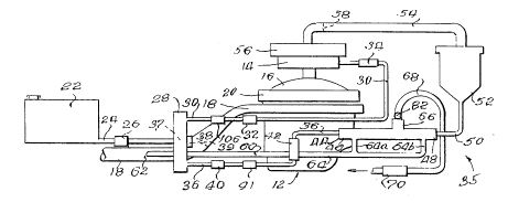
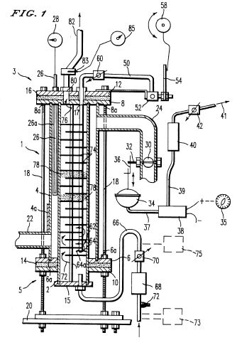
FIG. 1 is a diagrammatic view of the engine of an automobile and related components, and the apparatus of the present invention applied thereto;
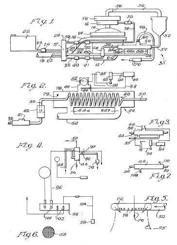
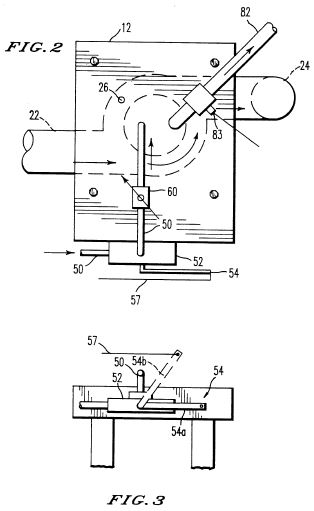
FIG. 2 is a vertical longitudinal sectional view of the vaporizer unit of the invention, oriented according to FIG. 1;
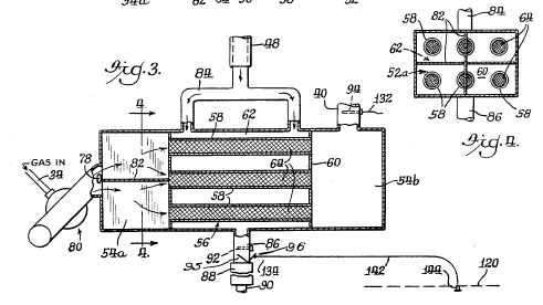
FIG. 3 is a view taken at line 3--3 of FIG. 2;
FIG. 4 is a view taken at line 4--4 of FIG. 3;
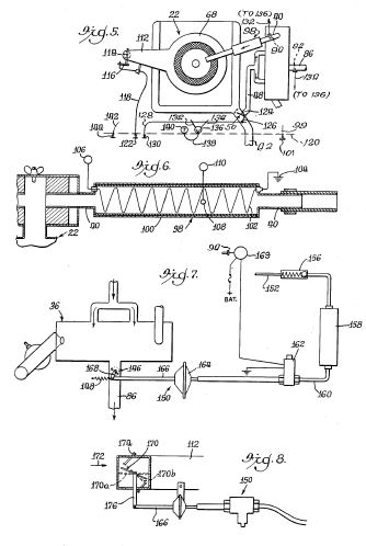
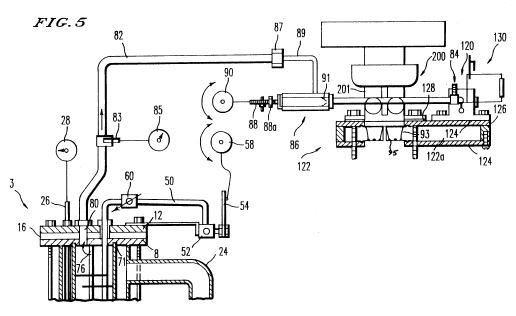
FIG. 5 is a semi-diagrammatic top view of the automobile engine and the fuel intake through the air cleaner, and related elements;
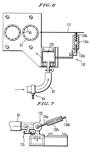
FIG. 6 is a longitudinal sectional view of a vapor tube electric heater included in FIG. 5;
FIG. 7 is a diagrammatic view of an arrangement for controlling the temperature of the vapor; and
FIG. 8 is a semi-diagrammatic view of an automatic choke for controlling the flow of vapor to the main carburetor.
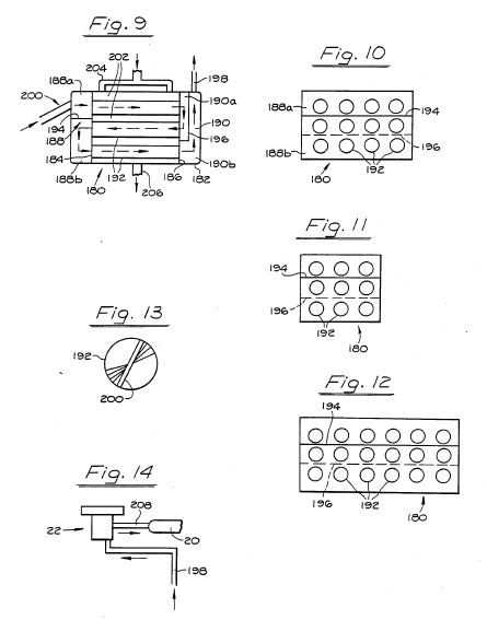
FIG. 9 is a sectional view of an alternate form of vaporizer unit.
FIG. 10 is an end view taken from the left of FIG. 9.
FIG. 11 is a semi diagrammatic view, oriented according to FIG. 10, showing a different number of tubes.
FIG. 12 is a view similar to FIG. 11, showing a still different arrangement.
FIG. 13 is an end view of a tube in the vaporizer unit.
FIG. 14 shows an alternate form of feed of the vapor to the engine.
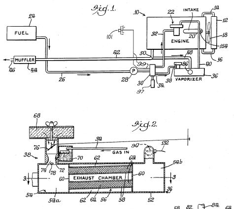
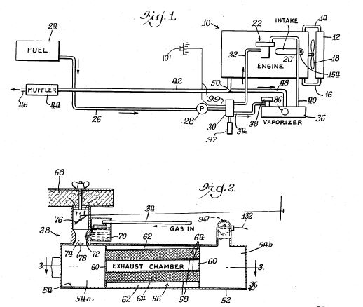
Referring in detail to the accompanying drawings, attention is directed first to FIG. 1 where the automobile engine is indicated at 10, having the usual radiator 12 included in a coolant system including fluid lines i4, 16, and the usual cooling fan 18.
The engine 10 includes an intake manifold 20 in which the vacuum is developed and sensed for performing certain operations referred to hereinbelow. The engine includes a main carburetor 22 and the usual fuel tank 24 from which the fuel is drawn through a main fuel line 26 in which is a fuel pump 28. The main fuel line 26 continues to a two-way valve 30 and from this valve leads a first branch fuel line 32 leading to the main carburetor 22, and a second branch fuel line 34 leading to the vaporizer unit 36, this unit constituting a principal component of the invention. The valve 30 as will be explained hereinbelow is operative for directing the fuel selectively through the branch lines 32, 34 and thus to the main carburetor 22 and the vaporizer unit 36 respectively in accordance with a certain sequence of operations referred hereinbelow. The vaporizer unit 36 includes an auxiliary carburetor 38 into which the second branch fuel line 34 leads. A vapor outlet line 40 leads from the vaporizer unit 36 to the main carburetor 22.
The engine 10 includes the usual exhaust pipe 42 in which a muffler 44 is included, and an exit tail pipe 46. A branch exhaust pipe 48 leads from the main exhaust pipe 42 at a juncture 50, leading to the vaporizer unit 36.
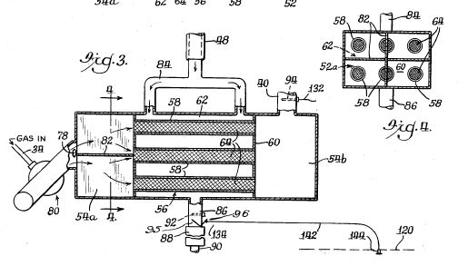
Attention is next directed to FIGS. 2, 3 and 4 showing the details of the vaporizer unit 36. The vaporizer unit includes an outer casing or shell 52 having a main chamber 54 therein, divided into two end chambers 54a and 54b by a tube structure 56 which includes a plurality of tubes 58, in this case six, leading between the chambers 54a, 54b. These tubes are mounted in end plates 60 which enclose the space 62 surrounding the tubes. The two end spaces 54a, 54b, and the tubes, constitute a longitudinal fuel passage through the unit, and the space 62 constitutes a transverse exhaust gas passage through the unit. The exhaust gases in that exhaust passage are in heat transfer relation to the tubes, for heating the fuel passing through the tubes, and vaporizing the fuel.
Preferably mesh elements 64 are placed in the tubes 58 these mesh elements being for example screen wire rolled into spirals and fitted into the tubes. The mesh units provide substantial open space for the fuel to pass therethrough, but the elements of the mesh also provide a great surface area for the particles of the atomized fuel to engage, greatly assisting the vaporization of the fuel. The fuel stream at this location is a mixture of atomized liquid fuel mixed in and carried by an air stream, produced by the auxiliary carburetor 38, and the engagement of the fuel particles with the elements of the screen mesh provide a dwell in the passage of the fuel therethrough, with greater effectiveness in vaporizing it. The vaporizer unit 36 normally assumes a position adjacent the horizontal, in the normal operation of the automobile, despite travel on inclines and the structure is such that the tubes 58 are inclined downwardly in direction opposite the direction of flow of fuel. In this instance (FIG. 2) the fuel flows generally from left to right, and the left ends of the tubes are lower than the right ends, enabling any liquid fuel that has not been vaporized to flow back, to be picked up by following increments of the air stream.
The auxiliary carburetor 38 of FIG. 2 is of known and standard type, operably associated with an air cleaner 68. The second branch fuel line 34 leads into a chamber 70 of the carburetor, from which the fuel then flows in atomized form through a nozzle 72 in the air passage 74 of the carburetor. A throttle body 76 is provided in the carburetor and manually set to a desired position, by means of a cable 77 having a manual knob 79 on the dashboard.
An electric crystal 78 is mounted at the inlet from the carburetor, for vaporizing the heavy ends of the fuel, vibrating at a frequency of in the neighborhood of one million vibrations per second. This crystal is actuated by a 12 volt current, provided by the usual battery of the automobile.
The auxiliary carburetor 38 shown in FIGS. 1 and 2 has a vertical outlet, and is positioned on top of the vaporizer unit, but a side outlet carburetor may be utilized instead, such as the carburetor 80 of FIG. 3, having an outlet leading into the chamber 54a. In the construction of the vaporizer unit of FIG. 3, cross vanes 82 (FIG. 4) are placed in the space 54a for directing the fuel more effectively into the tubes 56. In FIG. 3 also, the electric crystal 78 is utilized. FIG. 3 is a horizontal transverse sectional view and shows the branch exhaust line 48 (FIG. 1) connected to a manifold 84 which leads into the transverse exhaust passage 62, and leading from the latter is an outlet pipe 86 which may be provided with a muffler 88 and leading to the exterior at 90. FIG. 3 also shows the outlet vapor tube 40 which leads from the chamber 54b to the main carburetor 22.
A temperature sensing element 92 is positioned in the outlet pipe 86 and another temperature sensing element 94 is positioned in the vapor outlet pipe 48, and a flapper exhaust control 95 is provided in the exhaust line 86, and moved by a lever 96, as referred to hereinbelow, these elements being utilized for controlling the temperature of the exhaust vapor. The two-way valve 30 (FIG. 1) includes a solenoid 97 for actuating it, this controlled through the sensing element 92 in a known manner, directing the fuel to the vaporizer unit upon the exhaust gases reaching a predetermined temperature. If desired, the valve may be controlled manually by a Boden cable 99 (FIG. 1) having a knob 101 at the dashboard.
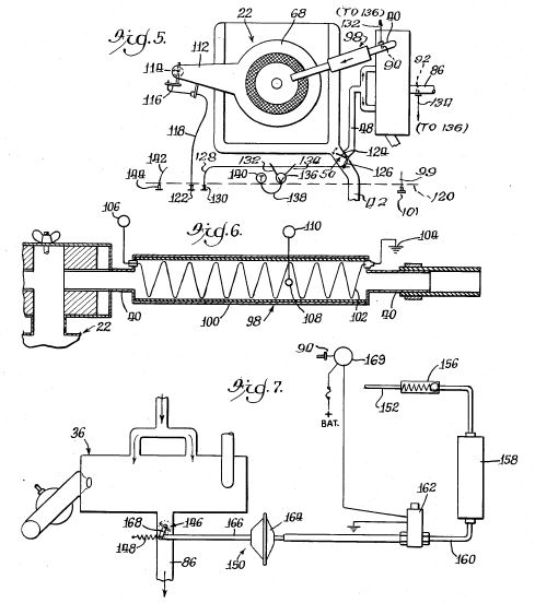
FIGS. 5 and 6 show an optional vapor tube heater 98, for use in such as winter climates, for providing additional heat to the vaporized fuel, being placed in the vapor outlet line 40 between the vaporizer unit and the main carburetor 22. It includes an outer tubular casing 100 and a resistance heater element 102 therein, in an electrical circuit which includes a ground 104 and a thermostat 106. A temperature sensing element o probe 108 is positioned in the unit for sensing the temperature of the fuel vapor therein and connected with a temperature indicating gauge 110, the temperature gauge and thermostat being operably interconnected in a known manner, for varying the resistance of the element for controling the temperature of the resulting fuel vapor.
FIG. 5, includes the main carburetor 22 and an air cleaner 111, the latter having an air inlet tube 112. The tube 112 has a choke valve 114 for varying the flow of the inlet air therethrough, this choke valve being operated by an arm 116 to which is connected a Boden cable 118 leading to the dashboard 120 and having a manual knob 122 thereon at that location. FIG. 5 also shows means for controlling the proportioned amount of exhaust gases flowing from the main exhaust pipe 42 (FIG. 1) to the branch exhaust pipe 48. At the juncture 50 of these lines is a flapper control valve 124 actuated by a lever 126, and leading from the lever is a Boden cable 128, continuing to the dashboard 120 where it is provided with a manual knob 130. These two manually actuated components may be provided in conjunction with automatically controlled components, as will be referred to hereinbelow.
FIG. 5 also shows the temperature probe 94 (FIG. 3) in the vapor outlet line 40, and the probe 92 in the outlet exhaust pipe 86, and conductors 132, 134, leading from those probes to a two-way switch 136 on the dashboard 120, and an additional conductor 138 leading from the switch to a temperature indicating gauge 140 also on the dashboard. The operator may turn the switch to either of its two opposite positions, for observing the temperature of the vaporized fuel in the vapor outlet line 40, or the exhaust gases in the outlet pipe 86, respectively.
It is found that the best operating temperature of the vaporized gas is approximately 250 DEG F., although it may be slightly higher than that, such as between 250 DEG F. and 260 DEG F. Upon observing the temperature of the vaporized fuel, by the temperature gauge 140 (FIG. 5) the driver may adjust, if need be, the passage of the outlet flow of exhaust gases through the pipe 86 (FIG. 3) by means of the flapper valve 95. A Boden wire 142 leads from the lever of the flapper valve to the dashboard 120 where a manual knob 144 is affixed thereto.
FIG. 7 shows an arrangement for automatically controlling the temperature of the fuel vapor. This figure shows the vaporizer unit 36 including the outlet exhaust gas pipe 86. In this outlet pipe 86 is a choke control 146 biased to closed position by a tension spring 148, and it is moved in opening direction by a unit indicated in its entirety at 150. This unit includes a line 152 connected with the intake manifold 20 (FIG. 1) at 154, and in this line is a check valve 156, the line 152 leading to a vacuum unit 158. Leading from the unit 158 is an air line 160 which continues through an air control valve 162 and then to a vacuum motor 164 of known kind, having a diaphragm actuated by air pressure. Connected to the diaphragm is an actuating rod 166, itself connected with an arm 168 on the choke control valve 146. The air control valve 162 is controlled by a thermostat 169 including the sensing element 94 (FIG. 3) in the vapor outlet line 40. Upon the temperature of the vaporized gas going above or below the predetermined values, as referred to above, the air control valve 162 is opened for controlling the vacuum condition which operates the motor 164. The vacuum in the engine, through the intake manifold, is transmitted through the line 152, releasing the check valve 156, producing a vacuum in the unit 158 which maintains a vacuum, or partial vacuum, at all times. Upon transmission of the vacuum from that unit through the line 160 as controlled by the air control unit 162, the vacuum is transmitted to the motor 164 and the external air pressure actuates the diaphragm of the motor, pulling the actuating rod 166 to the right, opening the choke control, that is, in response to a high vacuum, the motor is actuated a greater amount and opens the choke control and in response to a low vacuum, the choke control 146 closes or tends to close. This action may be start/stop or gradual as desired. As the choke control is opened or closed, the pressure of the exhaust gases in the vaporizer unit 36 is reduced or increased, respectively, with consequent variation of the temperature of the fuel mixture, including the vapor therein, produced by the exhaust gases.
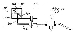
Attention is directed next to FIG. 8 which shows a portion of a device for automatically controlling the flow of air into the main carburetor 22 (FIG. 1). The tube or air arm 112 is provided with a second choke valve 170 for controlling the flow of air into the air cleaner which flows in the direction indicated by the arrow 172. It assumes a full open position as indicated at 170a which is adjacent the horizontal, and another position adjacent fully closed, is indicated at 170b, being limited in the latter direction by suitable means such as stop screws 174. Secured to the choke valve 170 is a lever arm 176, and secured to the latter is the actuating rod 166 of FIG. 7, of the unit 150, which is the same as that of FIG. 7. In the present case, FIG. 8, in response to high vacuum in the vacuum line 152, the choke valve is moved toward open position, and conversely, in response to low vacuum, it is moved toward closed position. The operation of the arrangement is such that as the choke 170 is moved toward closed position, the air through the air cleaner and into the main carburetor is restricted, and as a consequence, the draw on the vaporized fuel is greater. Hence this control means is effective for controlling the quantity of vaporized fuel to the engine, which is important in such cases as climbing steep hills.
The act of mixing the fuel by the auxiliary carburetor 38 may be termed a first carburetion, and that of mixing the fuel mixture from the vaporizor unit 36, with air, by the main carburetor 22, may be termed a second carburetion.
As noted above, both manual control and automatic control may be utilized for performing the same function--for example the manual control of FIG. 8, can both be utilized without interference with each other; similarly a manual control for the valve 95 (FIG. 3) for controlling the outlet exhaust vapor, and the automatic control of FIG. 7, can both be utilized for that function, without either interfering with the other.
FIGS. 9-13 show an alternate form of vaporizer unit, semi-diagrammatic form. Referring first to FIGS. 9 and 10, the vaporizer unit is indicated at 180, and includes an outer casing 182 with two vertical plates 184, 186, forming a fore chamber 188 and a rear chamber 190. Tubes 192 are mounted in the plates, arranged in parallel, communicating between the chambers 188, 190, and arranged in three vertically spaced, horizontal rows. A divider or baffle 194 divides the fore chamber into an upper sub chamber 188a and a lower sub chamber 188b, the upper sub chamber enclosing the front ends of the tubes, in the top row, and the lower sub chamber enclosing the front ends of the tubes in the two lower rows. A divider or baffle 196 divides the rear chamber into sub chambers 190a and 109b, the former enclosing the ends of the tubes in the upper two rows and the latter forming a passage between the tubes of the lower row to the vapor outlet line 198 leading to the main carburetor.
The auxiliary carburetor 200, of the side outlet type, leads at the side to the upper sub chamber 188a. The fuel mixture flows into the upper sub chamber forwardly (to the right, FIG. 9) through the tubes of the upper row, into and through the sub chamber 190a, then rearwardly through the tubes of the middle row, into and through the sub chamber 188b, and forwardly through the tubes of the lower row, and then through the sub chamber 190b and vapor outlet line 198.
The tubes 192 are preferably constructed as shown in FIG. 13, where a spiral copper insert or screw 200 is fitted in the tube. The tubes may be about 1/2" in internal diameter, and 8" long, these dimensions being examples.
The spaces between the tubes form a transverse exhaust passage 202, communicating between the engine exhaust pipe 204 and an outlet pipe 206.
This unit 180 of FIGS. 9 and 10 includes twelve tubes 192, but this number is determined by the capacity desired, such as nine in FIG. 11, or eighteen as in FIG. 12, for different sized automobiles.
FIG. 14 shows an alternate arrangement of feeding the vapor to the engine. The vapor outlet line 198 leads to the bottom of the main carburetor 22, then through the carburetor and a conduit 208 to the intake manifold 20.
Vaporizer/carburetor
US4611567
US4611567
A vaporizer unit has an enclosing casing including a plurality of tubes therein, defining a fuel passage therethrough, including the tubes. The tubes have coiled wire screen therein. An auxiliary carburetor is positioned at the inlet end of the fuel passage, and an outlet passage leads to the main carburetor of the automobile. The casing also defines an exhaust passage therethrough, transversely of the fuel passage, providing heat transfer between the exhaust gases and the tubes. The temperature of the resulting vaporized fuel is sensed for varying the flow of the exhaust gases and thereby controlling the temperature of the vaporized fuel, which is maintained at 250 DEG F. to 260 DEG F. An electric crystal is used for breaking down the heavy ends of the fuel. The rate of flow of air to the main carburetor is varied for correspondingly varying the rate of intake of vaporized fuel from the vaporizer unit. Automatic and manual controls are both utilized selectively, each without interfering with the other.
FIELD OF THE INVENTION
The invention resides in the general field of vaporizing liquid petroleum fuel for internal combustion engines, the most common example of which is in the case of automobiles.
OBJECTS OF THE INVENTION
A broad object of the invention is to provide apparatus and method in connection therewith, for vaporizing fuel, forming a complete and unified unit specially adapted for application to an engine, without requirement for predesigning the engine for that purpose.
Another object is to provide the foregoing apparatus, having the following features and advantages:
1. It includes a novel vaporizer unit especially effective for performing the vaporizing step.
2. It maintains the temperature of the vapor produced at such level as to provide most efficient combustion.
3. It provides a vaporizing step and produces the vapor in such quantity as to provide sufficient fuel for the engine in all instances, such as and particularly at high speeds and in climbing hills.
4. The apparatus is extremely simple in manufacture and in applying it to the engine, and effective in utilizing the facilities of the engine in the operation thereof.
DESCRIPTION OF A PREFERRED EMBODIMENT
In the drawings,
FIG. 1 is a diagrammatic view of the engine of an automobile and related components, and the apparatus of the present invention applied thereto;
FIG. 2 is a vertical longitudinal sectional view of the vaporizer unit of the invention, oriented according to FIG. 1;
FIG. 3 is a view taken at line 3--3 of FIG. 2;
FIG. 4 is a view taken at line 4--4 of FIG. 3;
FIG. 5 is a semi-diagrammatic view of the automobile engine and the fuel intake through the air cleaner, and related elements;
FIG. 6 is a longitudinal sectional view of a vapor tube electric heater included in FIG. 5;
FIG. 7 is a diagrammatic view of an arrangement for controlling the temperature of the vapor; and
FIG. 8 is a semi-diagrammatic view of an automatic choke for controlling the flow of vapor to the main carburetor.
Referring in detail to the accompanying drawings, attention is directed first to FIG. 1 where the automobile engine is indicated at 10, having the usual radiator 12 included in a coolant system including lines 14, 16, and the usual cooling fan 18.
The engine 10 includes an intake manifold 20 in which the vacuum is sensed for performing certain operations referred to hereinbelow. The engine includes a main carburetor 22 and the usual fuel tank 24 from which the fuel is drawn through a main fuel line 26 in which is a fuel pump 28. The main fuel line 26 continues to a two-way valve 30 and from this valve leads a first branch fuel line 32 leading to the main carburetor 22, and a second branch fuel line 34 leading to the vaporizer unit 36, this unit constituting a principal component of the invention. The valve 30 as will be explained hereinbelow is operative for directing the fuel selectively through the branch lines 32, 34 and thus to the main carburetor 22 and the vaporizer unit 36 respectively in accordance with a certain sequence of operations referred hereinbelow. The vaporizer unit 36 includes an auxiliary carburetor 38 into which the second branch fuel line 34 leads. A vapor outlet line 40 leads from the vaporizer unit 36 to the main carburetor 22.
The engine 10 includes the usual exhaust pipe 42 in which a muffler 44 is included, and an exit tail pipe 46. A branch exhaust pipe 48 leads from the main exhaust pipe 42 at a juncture 50, leading to the vaporizer unit 36.
Attention is next directed to FIGS. 2, 3 and 4 showing the details of the vaporizer unit 36. The vaporizer unit includes an outer casing or shell 52 having a main chamber 54 therein, divided into two end chambers 54a and 54b by a tube structure 56 which includes a plurality of tubes 58, in this case six, leading between the chambers 54a, 54b. These tubes are mounted in end plates 60 which enclose the space 62 surrounding the tubes. The two end spaces 54a, 54b, and the tubes, constitute a fuel passage through the unit, and the space 62 constitutes a transverse exhaust gas passage through the unit. The exhaust gases in that exhaust passage are in heat transfer relation to the tubes, for heating the fuel passing through the tubes, and vaporizing the fuel.
Preferably mesh elements 64 are placed in the tubes 58 these mesh elements being for example screen wire rolled into spirals and fitted into the tubes. The mesh units provide substantial open space for the fuel to pass therethrough, but the elements of the mesh also provide a great surface area for the particles of the atomized fuel to engage, greatly assisting the vaporization of the fuel. The fuel stream at this location is a mixture of atomized liquid fuel mixed in and carried by an air stream, produced by the auxiliary carburetor 38 and the engagement of the fuel particles with the elements of the screen mesh, provide a dwell in the passage of the fuel therethrough, with greater effectiveness in vaporizing it. The vaporizer unit 36 normally assumes a position adjacent the horizontal, in the normal operation of the automobile, despite travel on inclines, and the structure is such that the tubes 58 are inclined downwardly in direction opposite the direction of flow of fuel. In this instance (FIG. 2) the fuel flows generally from left to right, and the left ends of the tubes are lower than the right ends, enabling any liquid fuel that has not been vaporized to flow back, to be picked up by following increments of the air stream.
The auxiliary carburetor 38 of FIG. 2 is of known and standard type, having an air cleaner 68. The second branch fuel line 34 leads into a chamber 70 of the carburetor, from which the fuel then flows in atomized form through a nozzle 72 in the air passage 74 of the carburetor. A choke valve 76 is provided in the air passage, and manually set to a desired position.
An electric crystal 78 is mounted at the inlet from the carburetor, for vaporizing the heavy ends of the fuel, vibrating at a frequency of in the neighborhood of one million vibrations per second. This crystal is actuated by a 12 volt current, provided by the usual battery of the automobile.
The auxiliary carburetor 38 shown in FIGS. 1 and 2 has a vertical outlet, and is positioned on top of the vaporizer unit, but a side outlet carburetor may be utilized instead, such as the carburetor 80 of FIG. 3, having an outlet leading into the chamber 54a. In the construction of the vaporizer unit of FIG. 3, cross vanes 82 are placed in the space 54a for directing the fuel more effectively into the tubes 56. In FIG. 3 also, the electric crystal 78 is utilized. FIG. 3 is a transverse sectional view and shows the branch exhaust line 48 (FIG. 1) connected to a manifold 84 which leads into the transverse exhaust passage 62 and leading from the latter is an outlet pipe 86 which may be provided with a muffler 88 and leading to the exterior at 90. FIG. 3 also shows the outlet vapor tube 40 which leads from the chamber 54b to the main carburetor 22.
A temperature sensing element 92 is positioned in the outlet pipe 86 and another temperature sensing element 94 is positioned in the vapor outlet pipe 48, and a flapper exhaust control 95 is provided in the exhaust line 86, and moved by a lever 96, as referred to hereinbelow, these elements being utilized for controlling the temperature of the exhaust vapor. The two-way valve 30 (FIG. 1) includes a solenoid 97 for actuating it, this controlled through the sensing element 92 in a known manner, directing the fuel to the vaporizer unit upon the exhaust gases reaching a predetermined temperature. If desired, the valve may be controlled manually by a Boden wire 99 having a knob 101 at the dashboard.
FIGS. 5 and 6 show a vapor tube heater 98, for use in certain circumstances, such as in winter climates, for providing additional heat to the vaporized fuel, being placed in the vapor outlet line 40 between the vaporizer unit and the main carburetor 22. It includes an outer tubular casing 100 and a resistance heater element 102 therein, in an electrical circuit which includes a ground 104 and a thermostat 106. A temperature sensing element or probe 108 is positioned in the unit for sensing the temperature of the fuel vapor and connected with a temperature indicating gauge 110, the temperature gauge and thermostat being operably interconnected in a known manner, for varying the resistance of the element for controlling the temperature of the resulting fuel vapor.
FIG. 5 includes the main carburetor 22 and the air cleaner 68, the latter having an air inlet tube 112. The tube 112 has a choke valve 114 for varying the flow of the inlet air, this choke valve being operated by an arm 116 to which is connected a Boden cable 118 leading to the dashboard 120 and having a manual knob 122 thereon at that location. FIG. 5 also shows means for controlling the proportioned amount of exhaust gases flowing from the main exhaust pipe 42 (FIG. 1) to the branch exhaust pipe 48. At the juncture 50 of these lines is a flapper control valve 124 actuated by a lever 126, and leading from the lever is a Boden cable 128, continuing to the dashboard 120 where it is provided with a manual knob 130. These two manually actuated components may be provided in conjunction with automatically controlled components, as will be referred to hereinbelow.
FIG. 5 also shows the temperature probe 94 (FIG. 3) in the vapor outlet line 40, and the probe 92 in the outlet exhaust pipe 86, and wires 132, 134 leading from those probes to a two-way switch 136 on the dashboard 120, and an additional conductor 138 leading from the switch to a temperature indicating gauge 140 also on the dashboard. The operator may turn the switch to either of its two opposite positions, for observing the temperature of the vaporized fuel or the exhaust gases, respectively.
It is found that the best operating temperature of the vaporized gas is approximately 250 DEG F., although it may be slightly higher than that, such as between 250 DEG F. and 260 DEG F. Upon observing the temperature of the vaporized fuel, by the temperature gauge 140 (FIG. 5) the driver may adjust, if need be, the passage of the outlet flow of exhaust gases through the pipe 86 (FIG. 3) by means of the flapper valve 95. A Boden wire 142 leads from the lever to the dashboard 120 where a manual knob 144 is affixed thereto.
FIG. 7 shows an arrangement for automatically controlling the temperature of the fuel vapor. This figure shows the vaporizer unit 36 including the outlet exhaust gas pipe 86. In this outlet pipe 86 is a choke control 146 biased to closed position by a tension spring 148, and it is moved in opening direction by a unit indicated in its entirety at 150. This unit includes a line 152 connected with the intake manifold 20 (FIG. 1) at 154, and in this line is a check valve 156, the line 152 leading to a vacuum unit 158. Leading from the unit 158 is an air line 160 which continues through an air control valve 162 and then to a vacuum motor 164 of known kind, having a diaphragm actuated by air pressure. Connected to the diaphragm is an actuating rod 166, itself connected with an arm 168 on the choke valve 146. The air control valve 162 is controlled by a thermostat 169 including the sensing element 94 (FIG. 3) in the vapor outlet line 40. Upon the temperature of the vaporized gas going above or below the predetermined values, as referred to above, the air control valve 162 is opened for controlling the vacuum condition which operates the motor 162. The vacuum in the engine, through the intake manifold, is transmitted through the line 152, releasing the check valve 156, producing a vacuum in the unit 158 which maintains a vacuum, or partial vacuum, at all times. Upon transmission of the vacuum from that unit through the line 160 as controlled by the air control unit 162, the vacuum is transmitted to the motor 164 and the external air pressure actuates the diaphragm of the motor, pulling the actuating rod 166 to the right, opening the choke control, that is, in response to a high vacuum, the motor is actuated a greater amount and opens the choke control and in response to a low vacuum the choke control closes or tends to close. This action may be start/stop or gradual as desired.
Attention is directed next to FIG. 8 which shows a portion of a device for automatically controlling the flow of air into the main carburetor. The tube or air arm 112 is provided with a second choke valve 170 for controlling the flow of air into the air cleaner which flows in the direction indicated by the arrow 172. It assumes a full open position as indicated at 170a which is adjacent the horizontal, and another position adjacent fully closed, is indicated at 170b, being limited in the latter direction by suitable means such as stop screws 174. Secured to the choke valve 170 is a lever arm 176, and secured to the latter is the actuating rod 166 of FIG. 7, of the unit 150, which is the same as that of FIG. 7. In the present case, FIG. 8, in response to high vacuum in the vacuum line 152, the choke valve is moved toward open position, and conversely, in response to low vacuum it is moved toward closed position. The operation of the arrangement is such that as the choke 170 is moved toward closed position, the air through the air cleaner and into the main carburetor is restricted, and as a consequence the draw on the vaporized fuel is greater. Hence this control means is effective for controlling the quantity of vaporized fuel to the engine, which is important in such cases as climbing steep hills.
As noted above, both manual control and automatic control may be utilized for performing the same functioning--for example the manual control of the choke valve 114 of FIG. 5 and the automatic control of FIG. 8, can both be utilized without interference with each other; similarly a manual control for the valve 94 (FIG. 3) for controlling the outlet exhaust vapor, and the automatic control of FIG. 7, can both be utilized for that function, without either interfering with the other.
Carburetor/vaporizer
US4494516
US4494516
The fuel flows to the usual carburetor, initially, and when the engine heats up, the fuel is directed to a vaporizer, continuing through a line in the vaporizer, and then, as vapor, to the carburetor. In the vaporizer, the exhaust gasses flow over and around the fuel line and heat the fuel and vaporizes it. A two-way valve responds to the heat of the exhaust gasses and controls the flow of the fuel to the carburetor or the vaporizer. A single carburetor is used for both the unvaporized fuel and the vaporized fuel. A surge tank is included in the vapor line between the vaporizer and the carburetor. An alternate form utilizes the coolant of the engine for vaporizing the fuel.
FIELD OF THE INVENTION
The invention resides in the field of automotive vehicles and particularly those using petroleum fuel. Heretofore, in such vehicles the fuel was atomized for combustion purposes, but as such, it is basically in liquid form, as contrasted to vapor form.
OBJECTS OF THE INVENTION
A broad object of the invention is to provide a novel system for vaporizing petroleum fuel for use in automotive vehicles and particularly such having the following features and advantages:
1. It includes an unusually effective arrangement for vaporizing the fuel.
2. The exhaust gases are utilized to heat and vaporize the fuel, and controls are provided for regulating the development of the vapor through the amount of exhaust gases used and the effective temperature thereof.
3. The development of vapor is of such quantities as to provide full speed and power desired, in the engine.
4. It includes apparatus highly adaptable to retrofitting to vehicles.
DESCRIPTION OF A PREFERRED EMBODIMENT
In the drawings,
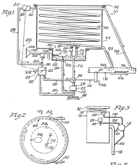
FIG. 1 is a general view, semi-diagrammatic in parts, of the apparatus of the invention applied to the engine of an automotive vehicle;
FIG. 2 is an enlarged view, partially in section, and partially diagrammatic, of certain elements of the apparatus of FIG. 1;
FIG. 3 is a diagrammatic view showing an alternative arrangement relative to that of FIG. 2;
FIG. 4 is a diagrammatic view of a series of controls for the apparatus, including instruments mounted on the dashboard of an automobile;
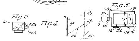
FIG. 5 is a detail view of an injector ring applied to the carburetor of the engine;
FIG. 6 is a detail view of a safety screen utilized in the apparatus; and
FIG. 7 is a diagrammatic view representing the use of the engine coolant for vaporizing the fuel.
Referring in detail to the accompanying drawings, attention is directed first to FIG. 1 showing the apparatus in its entirety as applied to the engine of an automotive vehicle, showing the various components thereof, as well as various components of the automobile, partially in diagrammatic form.
A principal feature of the invention is its great adaptability to retrofitting to an automobile. The disclosure herein includes certain basic and standard components of an automobile, and the components of the apparatus of the invention applied to the vehicle with virtually no change to those standard components, or a minimum of such change.
FIG. 1 includes the engine 12 of the vehicle having a diaphragm carburetor 14, an intake manifold 16 and an exhaust manifold 18. The arrangement also includes a valve cover 20, all of the foregoing elements being of known kind. The automobile includes the usual gasoline tank 22 from which a main fuel line 24 leads, the line including a fuel pump 26.
While the system of the invention is applicable to various automotive vehicles utilizing petroleum fuel, the most common example of such a vehicle is the automobile and for convenience the following description is somewhat keyed to that feature, although it is to be understood that the invention is not limited thereto.
The present apparatus includes a two-way valve 28 of suitable kind such as operated by an electric solenoid, the fuel line 24 leading to this valve and the valve being utilized for selectively directing the fuel to the carburetor incorporated in the vehicle, or to the vaporizer apparatus of the invention. Leading from the two-way valve 28 is a first extension fuel line 30 preferably containing a fuel filter 32 and continuing to the usual carburetor 14 referred to above. A fuel lock 34 may be incorporated in this line.
Also leading from the two-way valve 28 is a second extension fuel line 36 leading to the vaporizer component of the invention, which is indicated in its entirety at 35. The two-way valve 28 is controlled by a valve element 37 controlled by an electrical control 38, itself controlled by a heat sensor element 39 located in the exhaust gas line at a suitable location. Upon the temperature of the exhaust gasses reaching a predetermined point, the valve element 37 is moved to position for directing the fuel to the vapor unit. It also may be activated manually, as referred to below. The fuel line 36 preferably also has a fuel filter 40 and a manually adjustable fuel pressure regulator 41 of known kind. The line 36 continues and includes a suitable check valve 42 and then continues to a vaporizer unit 44 to be described in detail hereinbelow. The vaporizer unit includes a fuel inlet end 46 to which the fuel line 36 is connected, and a fuel outlet end 48 from which a fuel line 50 leads, this line leading to a surge tank or supply tank 52. The fuel vapor is directed to the surge tank 52 and provides a supply for the demands of the engine, and from this surge tank a vapor line 54 leads to the carburetor, and includes a vapor adapter 56 applied directly to the carburetor and constitutes the means for directing the vapor into the carburetor. Preferably the vapor line 54 includes a safety screen 58 (see also FIG. 5) to prevent the propagation of any flash into the vapor line.
The vaporizer unit 44 is supplied with exhaust gasses for vaporizing the fuel, and for this purpose, a hose or tube 60 leads from the engine exhaust manifold at 62 and continues to another tube which may be in the form of a metal pipe 64 having two inlet segments 64a and 64b leading through the vaporizer unit 44. The vaporizer unit includes an outlet element or casing 66 which leads to another tube or hose 68 which in turn is connected with muffler means 70 and then to the exterior.
Reference to FIG. 5 is made to show the construction of the vapor adaptor 56, which includes a tubular ring 72 having apertures 74 directed into the carburetor inlet 75, the vapor thus flowing through this ring and the apertures 74 downwardly into the carburetor. Upon operation of the engine and the usual intake draft, the fuel vapor is drawn into the engine as indicated by the arrow 76.
FIG. 2 shows details of the vaporizer unit 44 and associated elements shown in FIG. 1. FIG. 2 includes the pressure regulator 41 and check valve 42, and the fuel line 36 leading to the vaporizer unit 44. The vaporizer unit includes a casing or shell 78 generally closed and forming an exhaust gas chamber 79 therein, but the casing has openings specifically referred to. Mounted in the casing 78 is a coil 80 of suitable size according to the capacity desired, for accommodating the necessary fuel. This coil may be referred to as a vaporizer fuel line. The coil is of steel tubing of in the neighborhood of 1/2" diameter and of for example 12 to 20 feet of linear length. The fuel line 36 and vapor line 50 are of course sealed to the coil.
The fuel passing through the fuel coil 80 is vaporized by the heated exhaust gasses, these gasses flowing, as indicated above, through the exhaust line 64 into the interior or the casing or shell in heat exchange contact with the coil, which thereby vaporize the fuel. The amount of fuel vaporized, i.e., the amount of vapor produced is controlled by the amount or volume of exhaust gasses flowing through the unit 44. The exhaust gasses may be controlled at either the inlet side, or the outlet side, of the unit, selectively. An arrangement for controlling them at the outlet side is shown in FIG. 2, while an arrangement for controlling them at the inlet side is shown in FIG. 3.
Referring first to the arrangement of FIG. 2, the outlet element 66 referred to above is shown in this figure, and positioned therein is a control valve 82 which may be in the form of a choke having a wafer. This control valve controls the flow of exhaust gasses through the vaporizer unit, controlling both the volume and rate thereof. This control valve is controlled by an automatic electrical control module 84, controlled by a heat sensor element 86 mounted in the outlet element 66 of the casing, in heat sensing engagement with the exhaust gasses flowing therethrough. Electrical wires 88 lead from the sensor element to the module, and other electrical wires 90 lead from the module to a servo motor 92 which actuates an arm 94 connected at 95 with the control valve 82. The arrangement of this heat sensing component just described is such that upon the temperature reaching a certain predetermined maximum, the valve is shut down, or partially closed, and conversely when it reaches a certain minimum, the valve is opened. These steps control the evaporation of the fuel.
In the arrangement of FIG. 3, a valve 95, which may be of the same kind as the valve 82, is placed in the inlet line as referred to above, instead of in the outlet line. The control instruments 84, 86, 94, described above, are utilized in this instance. The location of the heat sensor element 86 is not limited to the outlet as represented in FIG. 2, but it may be located at any of various places in the exhaust line, either before or after the unit 44, or in the casing 78 of that unit itself.
The outlet element 66 or other element in which the heat sensor element 86 is positioned is preferably at least 3" in diameter, to accommodate a heat sensor element of desired length, which is preferably 3" or more in length.
In the normal operation of the engine and the apparatus, the valve 82, or95, is first left open, so that exhaust gasses will flow therethrough as the engine is started, and the vaporizer apparatus will normally operate in every use of the vehicle.
It is desired that certain manual controls be provided in addition to the automatic controls. Reference is made to FIG. 4 showing certain of these controls. For example, a cable element 96, preferably in the form of a boden wire is connected with an arm 97 of the control valve 82 and leads to the dash 98 of the automobile where a manually controlled member or knob 100 is located, enabling the driver to manually control the valve 82. FIG. 4 also shows the two-way valve 28 and a manually actuatable member 102 acting through a boden wire 104. Various other manual control elements may be mounted on the dash for manually controlling various other elements of the apparatus. Preferably, a manually controlled fuel pump 106 is provided in the fuel line 30, as an added feature.
It is also contemplated that the scope of the invention is such as to cover the vaporization of the fuel by the heated engine coolant. FIG. 7 represents such an arrangement, where the coolant flows from the engine through an inlet line 108 into the casing of the vaporizer unit 44, and out through an outlet line 110, in return to the engine.
In the operation of the apparatus, the vapor is drawn into the engine through the carburetor, and at a rate controlled by the carburetor as actuated by the driver.
Apparatus
for vaporizing fuel for engine in conjunction with
carburetor
US4368163
US4368163
A vaporizer chamber includes a coil therein, the coil having extensions extending into the exhaust pipe of the engine, the exhaust gases passing through the coil and heating the interior of the chamber. Fuel is delivered to the vaporizer chamber, and vaporized there when the exhaust gases are heated. A thermostat unit is mounted on the exhaust pipe, and when heated, shifts a valve to direct the fuel to the vaporizer chamber, instead of to the carburetor. This shifting is gradual. A throttle controls the flow of vaporized fuel to the outlet of the carburetor. The usual accelerator pedal is operative for controlling the throttle for the vaporized fuel in unison with the usual throttle provided in the carburetor. When starting the engine cold, it is fed atomized fuel from the carburetor, and when the engine warms up, the fuel to the carburetor is reduced, and that to the vaporizer chamber is increased, until only vaporized fuel is so fed, and in each case the delivery of fuel to the engine is controlled by the corresponding throttle in response to actuation of the same accelerator pedal.
FIELD OF THE INVENTION
The invention resides in the field of supplying fuel to a gasolene engine, the most common example of which is the case of the automobile. The invention further resides in the field of reducing the amount of fuel required for given power, and hence obtaining more miles per gallon.
OBJECTS OF THE INVENTION
A main and broad object of the invention is to provide a device and method for reducing the amount of fuel required for a gasolene engine for a predetermined amount of power.
Another broad object is to provide a device and method of the foregoing character which utilizes vaporized, as distinguished from liquid, fuel, but such used in conjunction with the usual atomized liquid fuel.
A still further object is to provide a device and method of the foregoing character having the following features and advantages:
1. It can be applied to an automobile engine virtually without altering the engine, and particularly without interfering with the carburetor incorporated as a standard accessory to an engine, except that when the engine is warmed up, the device of the present invention renders the carburetor ineffective, and supplies vapor to the engine.
2. The fuel is vaporized by the heat from the exhaust gases from the engine.
3. The feed of the vaporized fuel to the engine is controlled by the same mechanism, such as the accelerator pedal, that normally controls the standard carburetor, and with the further refinement that such accelerator pedal control is continuous through the transition from feed of atomized fuel to the feed of vaporized fuel to the engine.
4. It includes means for developing pressure by the radiator cooling air for assisting in controlling the feed of fuel vapor to the engine.
5. It includes a novel arrangement for pumping liquid fuel by the usual fuel pump, provided in an automobile, to a vaporized chamber, and for return of excess liquid fuel from the vaporizer chamber to the fuel pump.
6. The device is extremely simple, in materials required for making it, in fabrication of it, and in its functioning.
DESCRIPTION OF A PREFERRED EMBODIMENT
In the drawings:
FIG. 1 is a semi-diagrammatic view, showing the vaporizer chamber of the invention, in section, and other components in diagrammatic form;
FIG. 2 is a top view of the vaporizer chamber in FIG. 1;
FIG. 3 is a semi-diagrammatic view of an engine, and elements of the invention applied thereto;
FIG. 4 is a diagram of throttle means of the standard carburetor, and the throttle means of the present invention, actuated in unison by an accelerator pedal;
FIG. 5 is a diagram of a modified form wherein the fuel is vaporized by the coolant instead of the exhaust gases; and
FIG. 6 is a diagram of another modified form wherein the fuel is vaporized by an electric heater.
The invention will find ready adaptability to automobiles, but it is not limited thereto and can be applied to any internal combustion engine. Moreover, the device will be found most applicable, at least from a practical standpoint, to the use of gasolene as a fuel, but it is also applicable to other fuels. For convenience, in the present instance, the invention will be shown as applied to an automobile, with the above understanding as to the scope thereof.
Referring in detail to the drawings, a vaporizer chamber 10 is shown in large scale, in section as applied to an automobile engine. The engine is shown diagrammatically at 12 in FIG. 3, and includes a cooling radiator 14, and a cooling fan 16, the radiator and fan being standard items, the fan producing a stream of air, in its cooling operation, which is utilized for a specific purpose, as will be referred to again hereinbelow.
The engine includes a usual exhaust pipe 18, a carburetor 20 and a fuel pump 22. A fuel supply is indicated at 24. All of the foregoing elements or components are standard, and in the usual operation, the fuel pump 22 draws liquid fuel (gasolene) from the supply 24 through a fuel line 26 leading to the inlet of the fuel pump, and then through a fuel line 28 leading from the outlet of the pump. In the standard operation of the engine, the fuel continues through a fuel line 30 to the carburetor 20. Excess fuel, not utilized through the carburetor, returns through a first return line 32 to the inlet of the fuel pump, communicating with the supply 24. In the present instance a control valve 34 is provided in accordance with the principles of the present invention, and is interposed between the fuel lines 28, 30. The carburetor 20 has an outlet line 36 carrying atomized fuel to the engine, as indicated also in FIG. 3.
The carburetor 20, a standard and known component, has an air inlet line 40 through which air from atmosphere is carried thereto as controlled by a throttle 42, here identified a first throttle for mixture with the atomized gasolene for forming the combustible mixture required. The throttle 42 is controlled in the usual fashion, by means of an accelerator pedal 44 (FIG. 4) as will be referred to in again hereinbelow. The device of the invention includes another throttle 46, referred to for convenience as the second throttle, for controlling the vaporized fuel. The two throttles are interconnected by a link 48, which is directly actuated by the accelerator pedal 44 through a mechanism indicated diagrammatically at 50. The throttles 42, 46 are actuated in unison, by the accelerator pedal, and both in the same sense, that is, both opened or both closed.
The vaporizer chamber 10 includes a housing or tank 52 closed to the exterior except with respect to certain elements, as referred to again. The housing includes a cover 54, and it includes a bottom element 55, forming a well or pit 56, secured to the housing and surrounding an opening 58 in the bottom of the housing.
A tubing coil 60 is positioned in the chamber and has terminal extensions 62, 64 leading through to the exterior of the chamber, and extending into the exhaust pipe 18. The exhaust gases flow through the exhaust pipe as indicated by the arrow 66, and the first terminal extension 62 has a forwardly turned end element 68, forming a scoop for receiving a portion of the exhaust gases which are then forced into and through the coil 60 and then out through the other extension 64 where they are emitted through an end element 70 in the exhaust pipe. Thus a portion of the exhaust gases continuously flow through the coil 60 heating the vaporizer chamber.
Leading from the valve 34 (FIG. 1) referred to above, is another outlet fuel line 72, carrying fuel therethrough as determined by the setting of the valve 34. The line 72 continues to a "T" fitting 74 having arms 76 and each provided with a nozzle or jet 78, extending into the interior of the vaporizer chamber. Preferably the outlet ends of the nozzles are provided with a fine screen 80, of in the neighborhood of 100 mesh size. The mesh forms a spray or mist, indicated at 82, of the fuel, assisting the vaporizing action. The fuel thus delivered to the vaporizer chamber is vaporized by the heat from the exhaust gases, under conditions referred to hereinbelow.
Leading from the vaporizer chamber is a vapor feed line 84 in which is a control valve 86 which includes the second throttle 42 identified above. Continuing from this valve 86 is a feed line 88 which leads to the outlet of the carburetor, indicated at 90 as communicating with the outlet line 36 forming a standard element of the carburetor. The vapor from the vaporizer chamber flows through the feed lines 84, 88 and to the line 36, and then to the engine, in a manner referred to again hereinbelow.
In the normal operation, a certain portion of the fuel, i.e., the excess fuel, or that not needed for immediate use, in the vaporizer chamber, condenses and forms a liquid body 92 in the well 56. The temperature at which this condensation takes place may vary according to different factors, including pressure. A second, liquid fuel return line 94 leads from the well to the fuel line 26 at the intake of the fuel pump. The return of this liquid fuel from the vaporizer chamber is controlled by a needle valve 96 which in turn is controlled by a float 98 pivoted at 100 in the chamber. Upon the level of this liquid body 92 rising to a predetermined level, the needle valve opens and the liquid fuel returns to the inlet of the fuel pump, by means of pressure developed in the vaporizer chamber, and in certain circumstances, by means of gravity.
The pressure in the vaporizer chamber, referred to above, is developed by the delivery of the fuel into the chamber, but a small portion is also provided by a funnel or scoop 102 connected with a line 104 leading to the vaporizer chamber, and particularly at a point therein adjacent the bottom of the well 56, and in the body 92 of the liquid fuel. The funnel 102 is mounted in position as indicated in FIG. 3 where it scoops a portion of the air stream produced by the fan 16. Preferably a screen 106 is placed over the inlet of the funnel. This pressure thus developed in the vaporizer chamber, from the fan, is in proportion to the speed of the cooling fan 16, and thus in proportion to the speed of the engine. This pressure may be as low as 1/2 lb. psi, and it may rise to in the neighborhood of 6-8 lbs. psi. This arrangement results in the introduction of a certain amount of air into the vaporizer fuel, but this air, from the fan, is only a small portion of the air utilized in forming the combustible mixture, being on the order of 1%-2% thereof. The remaining air is provided through the carburetor, under the usual control of the carburetor.
The valve 34 is controlled by a thermostatic unit 108 which is mounted on the exhaust pipe 18, and includes a heat sensing element 110 extending into the interior of the exhaust pipe for sensing the temperature of the exhaust gases. The unit 108 is provided with a link or element 112 leading to the valve 34 for actuating the latter. When the exhaust pipe is cool, the unit 108 acts to shift the valve 34 to a first position for directing fuel from the line 28 to the line 30 and thereby to the carburetor. In this condition the engine operates as if the device of the present device is not applied thereto. When the exhaust gases reach a predetermined temperature, the unit 108 serves to shift the valve 34 toward and to a second, and opposite, position, directing the fuel from the line 28 through the line 72 and to the vaporizer chamber.
In the operation of the apparatus, and assuming first a cold condition, when the engine is started, the valve 34 directs the fuel to the carburetor, and it is there atomized and delivered to the engine in the usual manner. In this stage of operation there is no vaporized fuel developed. The engine is under the control of the accelerator pedal 44 which actuates the throttle 42 of the carburetor in the usual manner, allowing less, or more, fuel to the engine. Actuation of the accelerator pedal also controls the second throttle 46, at the same time, but at this stage, no fuel has been vaporized and the fuel lines 84, 88 are empty.
As the engine warms up consequent to running, and the exhaust gases heat up, these exhaust gases, in passing through the coil 60, heat up the coil, and thus the interior of the chamber. Simultaneously therewith, pursuant to the heating up of the exhaust gases, the thermostatic unit 108 functions to switch the valve 34, toward its second position, whereby the fuel is directed from the fuel line 28 through the line 72 and to the vaporizer chamber. The valve 34 is preferably of gradually closing/opening character, so that as it moves from its first position in which it directs fuel to the carburetor, to its second position in which it directs fuel to the vaporizer chamber, it does so slowly. As a consequence the fuel to the carburetor is gradually reduced and the fuel to the vaporizer chamber is gradually increased. Thus the engine starts on the atomized fuel, and continues on both the atomized fuel and vaporized fuel in a gradual transition step, that is, at the first portion of that step, the fuel is entirely atomized, and that fuel gradually lessens and the vaporized fuel gradually increases, so that there is a mixture of the two conditions or phases of the fuel between the extremes until all of the atomized fuel is shut off, and only the vaporized fuel flows to the engine. All through this phase, both throttles 42, 46 are actuated in unison as mentioned above, and even though they both are so actuated, the fuel that is delivered to the engine is controlled by the one that is in the stream of fuel. While the valve 34 moves toward its second position and shuts off fuel to the carburetor, the throttle 42 remains open, according to the actuation of the accelerator pedal 44 so that the throttle 42 permits sufficient air for producing proper combustible mixture with the vaporized fuel from the line 88. Although the fuel to the carburetor is shut off, and the carburetor does not function in controlling the flow of fuel, it does however remain operative in controlling the flow of air for mixture with the vaporized fuel.
It is also within the scope of the invention to vaporize the fuel from the heat of the engine coolant, instead of from the exhaust gases. Such an arrangement is shown in FIG. 5, which includes the engine 12, radiator 14, fan 16 and the vaporizer chamber 10. This arrangement includes a tube 114 for carrying the coolant from the engine to the radiator, and a return line 116. The hot coolant from the line 114 also is carried by a line 118 to the inlet extension 62 of the vaporizer chamber and a line 120 from the outlet extension 64 to the cool return line 116.
Furthermore, the invention is sufficiently broad to cover any kind of external heater, including an electric heater element. FIG. 6 shows such an electric heater 122 in the vaporizer chamber 10, connected with conductors 124 leading from a suitable source such as the battery 126 in the automobile.
Accordingly, the operator performs the operating steps, for driving the engine, in exactly the same manner as he would without the apparatus of the present invention applied thereto. In other words he actuates the accelerator pedal 44, and the fuel delivered to the engine is of atomized form, or vaporized form, according to the condition of the engine itself, that is, the temperature thereof, and there is no requirement for a special manipulation required because of the change of fuel.
In order to apply the apparatus of the invention to an ordinary engine, there is an absolute minimum of adaptation required. The apparatus is simply applied to the engine, and the engine and related components are not in any way affected from the standpoint of constructional features. The coil terminal extensions 62, 64 do however extend through the holes in the exhaust pipe, as does the thermostatic unit 108, but these holes are minimal, and it is also within the scope of the invention to provide a fitting containing these elements that may be simply interposed as a section in the exhaust pipe.
The temperature at which the switch-over from atomized fuel to vaporized fuel may be as desired, such for example as between 110 DEG F. and 160 DEG F. in the vaporizer chamber. This temperature is determined of course by pre-selecting elements of the desired characteristics.
Tests have proved that standard automobiles now on the road, provided with the device of the invention, have obtained greatly improved mileage.
The apparatus is relatively small, and can be easily accommodated under the hood of most automobiles. In the case where space is at a premium, the apparatus may be re-designed to the particular space available. As an example of the approximate size of the apparatus, the vaporizer chamber 10 may be on the order of 7" in diameter, and the main housing 5" deep, in axial direction. The well 56 may be for example 2" in axial direction. Obviously these dimensions are not considered limiting, but merely as examples. The vaporizer chamber constitutes the largest component of the apparatus, and from that, and the relative sizes of the other components, can be visualized that a very small space is required for the entire apparatus.
US5291870
FUEL VAPORIZING SYSTEM
FUEL VAPORIZING SYSTEM
A system for providing an air-fuel vapor mixture to an engine for improving completeness of combustion and also reducing emissions. The system includes a vaporizer within which a series of baffles are disposed such that air and fuel pass along a tortuous passageway defined within the vaporizer. Exhaust gases provide heat to the vaporizer, and as air and fuel pass along the passageway of the vaporizer, a homogenous air-fuel vapor mixture is produced, with the homogenous mixture exiting the vaporizer being supplied to the engine by way of an adapter plate assembly. When used with a carburetor, the adapter plate is disposed between the carburetor and the engine.
BACKGROUND OF THE INVENTION
1. Field of the Invention
The invention relates to fuel systems, and particularly to fuel systems which heat the fuel such that the fuel enters an engine as a vapor.
2. Discussion of the Background
It is constantly a goal to improve the performance of engines, particularly in automobiles and other motor vehicles. Due to the competitiveness of the industry as well as environmental constraints, motor vehicle engines must operate as efficiently as possible while minimizing emissions and providing satisfactory power performance. Toward these goals, one focus has been upon the ability to provide most efficient and complete combustion of the fuel consumed by the engine. In order to improve combustion of the fuel, one approach has been to heat the fuel to a vapor before the fuel enters the engine.
For example, in my earlier U.S. Pat. No. 4,883,616, a fuel system is disclosed in which the fuel passes from the fuel tank to an auxiliary carburetor, with the auxiliary carburetor providing an air and fuel mixture to a vaporizer unit. The vaporizer unit then heats the mixture such that the fuel is vaporized, and the vapor is then fed to the main carburetor of the engine. Although the system utilizes the concept of providing vaporized fuel to an engine, the system has been less than optimal from a power performance standpoint.
Other attempts to provide improved engine performance, emissions and economy utilizing vaporized fuel have also suffered from a number of shortcomings. Some attempts have suffered from the inability to adequately control the vapor and achieve full engine power in all driving conditions. In other attempts, the vapor produced condensed as it was traveling from the vaporizer toward the engine, somewhat defeating the purpose of the vaporizer.
Accordingly, an improved fuel delivery system is desired which provides a more optimal and effective fuel and air mixture to the engine. Such a system should be capable of providing an air and fuel mixture in a vaporized state such that fuel efficiency is increased while emissions are decreased. Preferably, the system should be adaptable to retrofit installation a well as for manufacture with the original equipment.
SUMMARY OF THE INVENTION
Accordingly, it is an object of the present invention to provide a fuel heating system which provides an air-fuel vapor mixture to an engine to increase the fuel efficiency and decrease emissions.
It is another object of the present invention to provide a vaporizer for a fuel system which can be installed on a retrofit basis, and which also can be incorporated in the original equipment when the engine is manufactured.
It is yet another object of the present invention to provide a vaporizer for a fuel delivery system in which the fuel and air pass along a convoluted or tortuous passageway such that the fuel is fully vaporized and mixed with air, thereby providing a homogenous air-fuel vapor mixture to the engine.
It is another object of the present invention to provide a fuel delivery system in which a homogenous air and fuel vapor mixture is formed which does not condense when traveling from the vaporizer toward the engine.
It is a further object of the present invention to provide a fuel supply system which includes a vaporizer, and which can be utilized in an engine having a carburetor as well as a fuel injected engine.
It is a still further object of the present invention to provide a vaporizing fuel supply system which can be utilized when conditions are appropriate, with the system switchable to the standard carburetor or fuel injection system at other times.
BRIEF DESCRIPTION OF THE DRAWINGS
A more complete appreciation of the invention and many of the attendant advantages thereof will be readily apparent from the following detailed description, particularly when considered in conjunction with the drawings i which:
FIG. 1 illustrates a vaporizing device for use in the fuel delivery system of the present invention, in partial cross-section;
FIG. 2 is a top view of the vaporizing device of the present invention showing the various connections of the top plate;
FIG. 3 is a side view of the upper plate shown in FIG. 2, depicting the fuel-in adjustment valve which can control the amount of fuel delivered to the vaporizer;
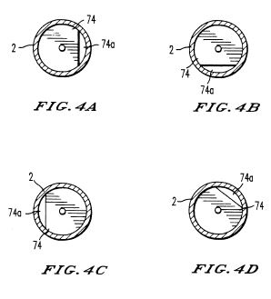
FIGS. 4A-D depict various orientations of baffles arranged along the vaporizer of the present invention;
FIG. 5 shows the arrangement in which the vapor (exiting from the vaporizer) enters the engine with portions of the vapor introduction adapter assembly in section;
FIG. 6 is a plan view or top view of the adapter plate assembly of FIG. 5;
FIG. 7 is a side view of the adapter plate assembly together with the connection of the adapter plate throttle to the carburetor throttle linkage;
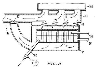
FIG. 8 illustrates an alternate arrangement in which the vaporizer of the present invention is disposed horizontally and housed adjacent the engine exhaust manifold;
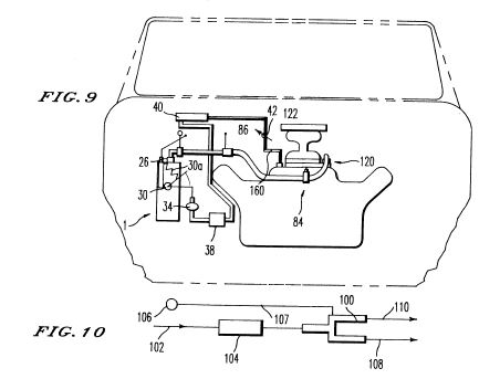
FIG. 9 schematically illustrates the overall fuel delivery system; and
FIG. 10 schematically illustrates a valve arrangement to allow for switching between vapor and standard carburetor or fuel injected operation .
DESCRIPTION OF THE PREFERRED EMBODIMENTS
Referring now to the drawings, wherein like reference numerals designate identical or corresponding parts throughout the several views, FIG. 1 illustrates the vaporizer fuel system of the present invention in which the vaporizer includes an inner housing 2 formed preferably of red brass, with the housing sufficiently sealed such that the air and fuel being mixed and vaporized within the housing do not escape therefrom, and so that exhaust gases which circulate between a steel outer housing 4 and the inner housing 2 do not enter the inner housing 2. I have found red brass to be the best in handling high temperatures associated with the vaporizer fuel system. The outer housing 4 is welded or soldered (silver solder) to the exhaust in and out pipes, and can also be welded to the bottom plate 6. The housing 4 may also be tightly fitted into a groove 8a of the upper plate, thereby allowing for disassembly, while preventing leakage when assembled. The outer housing can also be seated in a precisely cut groove (6a) in the bottom plate 6. Additional end plates 10, 12 are also provided, with high temperature gaskets 14, 16 sandwiched between the plates. The vaporizer structure is also held together by bolts 18, which also allow for mounting the vaporizer upon a suitable support 20 on the vehicle. The inner housing is preferably welded or soldered (silver solder) to an end plate 15, with the other end received in groove 17 of plate 8 when the arrangement is assembled and tightened via bolts 18. Silver solder can be used for fixing the inner housing to the upper and lower plates.
The arrangement of FIG. 1 is advantageous in that it allows for easy assembly and disassembly of the various components, thereby allowing for inspection, repair or modification. Disassembly can also allow for cleaning, for example utilizing a conventional carburetor cleaner. However, it is to be understood that disassembly may not be essential in mass-produced versions, and therefore instead of a bolted arrangement, an overall welded construction may suffice, or a construction in which only the top is removable. In both the bolted and welded constructions, it may also be desirable to provide a drain (not shown) in the bottom to allow draining of any cleaning materials.
An inlet pipe 22 provides a source of heat for the vaporizer. In the preferred form of the invention, the exhaust pipe or conduit 22 is connected to the exhaust system of the vehicle. For example, the conduit 22 can be connected to the exhaust manifold, or to a location downstream of the exhaust manifold. The exhaust enters the conduit or pipe 22 and circulates within the outer housing and about the inner housing, and then exits through the exhaust outlet conduit or pipe 24. A temperature sensing probe 26 extends into the space between the inner and outer housing to thereby provide an indication of the temperature of the exhaust gases in order to determine when the temperature is sufficient for proper operation of the vaporizer. Preferably, the probe is contained within a red brass tube 26a to prolong the life of the probe. The probe 26 connected to a temperature gauge and/or control 28 which is displayed on the dash of the vehicle. The temperature gauge can be utilized by the operator to determine when the exhaust temperatures are sufficient such that the vaporizer is operational, and thereafter, the heat is controlled by an AC/DC vacuum solenoid, solenoid, vacuum storage and vacuum element together with a thermostat. An example of a suitable exhaust temperature control is disclosed in my earlier U.S. Pat. No. 4,883,616, which is incorporated herein by reference.
The choke plate 30 pivots by way of a bolt 32 which is rotated by a vacuum element 34. The vacuum element is connected to the bolt 32 by a suitable link such as piano wire 36. The vacuum element 34, in turn, is connected to a vacuum solenoid valve 38 by line 37. The vacuum solenoid valve 38 selectively places the line 37 in communication with a vacuum line 39 connected to a vacuum storage location 40. The vacuum solenoid valve 38 is operated by the thermostat, which preferably includes an electric temperature control dial 35 located on the dash to allow the thermostat temperature to be varied. The choke plate 30 is shown in the open position in FIG. 1, and when rotated 90 DEG, the plate 30 is in the closed position. The vacuum storage 40 can be approximately two inches by four inches and is connected to the engine vacuum as indicated by arrow 41, with a one-way check valve 42 provided to prevent loss of the vacuum in the vacuum storage 40 (see also the connection 160 to the engine vacuum in FIG. 9). Although the size of the various elements can depend on a number of parameters, for example the size of the engine to which fuel is being supplied, the size of the outer housing can be, for example, on the order of 3-4 inches for automobiles. The inner red brass housing can be, for example, 1/2-2 inches in diameter and 12-16 inches in length. Preferably, the entire outer housing is insulated as represented schematically at 4a.
Fuel is supplied to the inner housing by way of a fuel inlet conduit 50. Fuel travels from a variable on/off valve 52 which includes an arm 54 for actuating the valve 52, with a suitable control 58 (FIG. 5) provided on the dash of the vehicle. The control 58 can be, for example, an adjustable push-pull knob, with the control connected to arm 54 by a cable, such as an aircraft bowden cable. For example, one type of knob, which is commercially available, provides adjustment when the knob is in the out position by rotating the knob, which in turn is associated with a screw. The knob can also be pushed in for an immediate cut-off, for example in an emergency. Of course, other types of knobs or switches could be implemented within the scope of the present invention. Generally, the valve 52 will not be adjusted often, and typically only one adjustment or long term periodic adjustments are necessary for a particular engine. However, adjustment may also be necessary where operating conditions or loads change dramatically. Particularly in more automatic designs, adjustment of the valve 52 from under the hood (rather than from the dash) may be sufficient. A one-way check valve 60 is disposed in the fuel inlet conduit 50, thereby preventing any backflow or back pressure from the interior of the inner housing.
Referring briefly to FIG. 10, a switching/valving arrangement is provided to allow for operation of an engine via the vaporizer, or by the standard carburetor or fuel injector. The FIG. 10 arrangement is upstream of the valve 52 and includes a two-way valve 100, preferably a two-way solenoid. Fuel is supplied via line 102 and filter 104, with an electric actuator switch 106 operating the valve 100 such that the fuel from line 102 passes either to the vaporizer as indicated by arrow 108, or to the standard carburetor/fuel injector as shown at 110. Once the exhaust temperature gauge indicates the exhaust temperatures are sufficiently high (e.g., 550 DEG F. minimum), the operator can utilize the electric switch to change from standard operation to operation by fuel from the vaporizer. When operation by the vaporizer is desired, the operator flips the switch 106, which is electrically coupled (107) to the solenoid 100. The switch 106 actuates solenoid 100 such that flow is discontinued to the carburetor and fuel begins flowing to the vaporizer. Alternatively, the control switch 106 could include an automatic control arrangement or automatic switchover such that the fuel is delivered to the vaporizer (i.e., to the interior of the inner housing 2) automatically when the exhaust temperatures are sufficient. However, even where the control of the fuel flow to the inner housing 2 is automatically controlled, a manual override should be provided such that the operator can discontinue fuel supply via the vaporizer when desired.
Typically, the exhaust temperature should be 550 DEG-700 DEG F. to operate the engine with the vaporizer, however, the temperature can vary dependent upon the type of fuel being vaporized.
As should be readily apparent from FIG. 1, the fuel supply conduit 50 enters a first end of the vaporizer and inner housing through the plates 8, 12 and the gasket 16, with the fuel inlet conduit extending from a first end, designated generally at 3, and toward a second end, designated generally at 5, of the vaporizer and inner housing. As a result, the fuel begins to be heated as it passes through the inner housing within the fuel inlet conduit. At the terminating end of the fuel inlet conduit 50, a nozzle portion 62 is provided. Preferably, the nozzle portion 62 includes a plurality of small outlet holes 64 disposed in the side walls of the conduit 50. The outlet holes are on the order of 10-20 thousandths of an inch and thereby disperse the fuel as it exits (as illustrated at 64a) the nozzle portion and is released into the interior of the inner housing 2. The size of the outlet holes 64 can also vary with engine size. The end of the conduit or fuel inlet 50 is preferably closed such that the fuel is released only via ports or holes 64. Although the fuel inlet 50 is illustrated as substantially a single continuous conduit, it is to be understood that the high temperature materials (e.g., brass) for conduit portions extending into the inner housing need not be utilized for the entirety of the conduit 50.
An air inlet conduit or line 66 is also provided for supplying air to the inner housing for mixing with the fuel. Air enters the conduit 66 from the ambient atmosphere, and passes through a filter 68 and one-way check valve 70. In addition, an adjustment device, such as an adjustable screw device 72 is provided in order to adjust the amount of airflow from the ambient to the inner housing of the vaporizer, e.g. for various engine sizes. In addition, a source of compressed air 73 may optionally be provided, which can be selectively placed in communication with the conduit 66. The operation of the vaporizer with compressed air may be desirable in certain high-power operations, such as in climbing a steep hill and/or carrying a heavy load. However, under most conditions, it will be sufficient to operate the vaporizer with the conduit 66 open to ambient air, since the movement of the air and fuel through the inner housing will cause the air to be drawn from the ambient through the air inlet conduit 66. In fact, in accordance with one aspect of the present invention, I have recognized that by simply providing the air inlet open to ambient, the mixture formed by the vaporizer is superior to introduction by known methods such as an auxiliary carburetor or compressed/forced air, under most operating conditions.
A small amount of water may also (optionally) be pumped into the air inlet conduit 66 as illustrated at 75. This can include an automatic electronic water injection system 75 available at parts stores. The water becomes steam in the vaporizer and even further reduces emissions of the engine to near zero. The steam can also help the interior of the inner housing stay clean. With the vaporized fuel delivery system of the present invention, emissions have been reduced to 3-8% of that of standard carburetor/fuel injection operation without the use of water. The emissions reduction is enhanced by the addition of water to near zero. For wintertime operation, the water can be a windshield washer type fluid which includes alcohol to prevent freezing.
The air enters the inner housing at the second end (5) of the inner housing such that it is mixed with fuel exiting the fuel inlet conduit 50. As the fuel exits through the nozzle portion 62, it is mixed with air and vaporization of the fuel begins within the heated inner housing 2. In order to ensure complete vaporization of the fuel, and mixing with air, the air and fuel travel along a convoluted or tortuous passageway indicated by the arrows 72.
The arrangement of the interior of the inner housing is an extremely important aspect of the present invention. As discussed earlier, one problem with previous vaporization arrangements has been that the vapor at least partly condenses as it travels from the vaporizer to the engine. However, in accordance with the present invention, complete vaporization of the fuel occurs in the vaporizer, and further, the vapor is mixed with air such that a uniform homogenous air and fuel vapor mixture is provided. Testing has revealed that the vapor mixture provided by the vaporizer of the present invention has been able to maintain its vapor condition for as long as 20-25 minutes after exiting the vaporizer before condensing again. Accordingly, problems associated with condensation of the vapor as it travels from the vaporizer to the engine are avoided, since the vaporizer provides a superior homogeneous air-fuel vapor mixture.
The passageway for the air and fuel is defined by a number of baffles 74 (preferably red brass) disposed along the interior of the inner housing 2. For convenience, it is preferable that the baffles 74 be mounted (e.g., with silver solder) upon a center rod 76 which extends through the housing. With such a construction, the baffles can be conveniently removed for repair, cleaning or inspection merely by removing the top plate of the vaporizer and removing the rod 76 having the baffles mounted thereon. A number of pads 78 may also be disposed along the passageway defined between the baffles, with the pads 78 formed of a brass wool or mesh. The brass wool pads 78 increase the effectiveness or completeness of the vaporization of the fuel, since the fuel must come in contact or pass very closely adjacent to the strands of the brass pads, which become hot when the vaporizer is in use. The brass wool pads also make the passageway even more tortuous, thereby improving vaporization and homogeneity of the mixture.
Once the fuel and air has passed along the passageway defined within the inner housing 2, the fuel has become completely vaporized and the homogenous air-fuel vapor mixture exits the vaporizer through a vapor outlet 80, and into a vapor conduit 82. A vapor temperature probe 83 can also be provided, with a vapor temperature gauge 85 mounted on the dash. The vapor conduit 82 should be insulated (not shown) along its length to assist maintaining the vapor state.
FIG. 2 shows a top view of the vaporizer unit. Although the unit is illustrated in a vertical orientation (FIG. 1), it is to be understood that the vaporizer may also be disposed underneath a hood of a vehicle such that the vaporizer extends horizontally. A horizontal arrangement may be advantageous in providing a more compact design, however, a vertical arrangement can provide for easier access to the interior of the vaporizer by removing the plate 12 from the bolts (allowing for inspection, repairs or modification through testing). As shown in FIG. 2, the exhaust enters conduit 22, circulates between the inner and outer housings, and exits through conduit 24. The fuel travels through the fuel inlet conduit 50 through valve 52, and continues to travel through the conduit 50 via one-way check valve 60 and into the interior of the inner housing 2, with the homogenous air-fuel (and water or steam) vapor exiting through vapor outlet conduit 82.
FIG. 3 is a side view of the top or first end (3) portion of the vaporizer unit of FIGS. 1 and 2. A bowden cable 57 operates a valve arm 54 for the valve 52. The valve arm is movable between an off position 54a and a full on position 54b to vary the amount of fuel passing along conduit 50 to the interior of the inner housing 2.
Briefly referring to FIGS. 4A-D, the baffles include a plurality of circular plates 74, preferably formed of red brass, with a sector of each plate missing as shown at 74a, to thereby define the passageway for the air and fuel vapor along the inner housing. For clarity, the fuel inlet conduit 50 is omitted from FIGS. 4A-D, however, it is to be understood that at least some of the baffles will include an aperture through which the conduit 50 extends. As shown in FIGS. 4A-D, the baffle plates 74 are angularly offset with respect to one another, such that the removed sectors of adjacent baffles are not axially aligned with one another. For example, a first plate may have an orientation as shown in FIG. 4A, with an adjacent plate oriented as shown in FIG. 4B, and subsequent plates arranged as shown in FIGS. 4C and 4D. As a result, a convoluted or tortuous passageway is defined within the inner housing, thereby promoting complete vaporization of the fuel and also promoting homogeneity of the fuel and air mixture. In addition, the baffles promote a regular and controlled or confined flow of the air and fuel, since without the baffles, the fuel would expand quite rapidly upon entering the inner housing or vapor tube 2, and would explode in all directions without developing a homogenous air-fuel mixture in which the fuel is fully vaporized. Still referring to FIGS. 4A-D, it will be noted that the removed sectors are offset in a clockwise direction with respect to one another when the successive baffles of FIGS. 4A-D are compared. In order to provide an even more tortuous passageway, the baffles are preferably arranged such that subsequent baffles are offset counterclockwise with respect to one another. As a result, during some portions of the passageway along the inner housing, the air and fuel vapor will travel along a somewhat helical path in a first direction, with the helix then reversing in another direction.
Thus, the baffles inside of the inner housing promote flow of the air and fuel mixture toward the vapor outlet 80, and also promote complete vaporization and homogeneity of the mixture. The vapor leaves the inner housing via vapor conduit 82, has its temperature taken via probe 83 and gauge 85, and is supplied to the engine as shown in FIG. 5. Preferably, an adjustment screw 84 is disposed along the vapor conduit 82 to thereby adjust the flow along the conduit, with the screw 84 as close as possible to the throttle 120. Preferably, the screw 84 includes a lock-nut to maintain the adjusted position of the screw. For an automobile, the vapor conduit is on the order of 1/2-1 inch, with the actual size depending upon the size of the engine. In order to ensure that the engine is not simultaneously fed fuel from the vapor conduit 82 and through the carburetor at the same time, a pintle valve 86 is also disposed between the vapor conduit 82 and an adapter plate assembly 122 which is disposed beneath the engine carburetor. Alternatively, a solenoid valve could be utilized instead of a pintle valve, however, high temperature solenoid valves can be quite costly. The pintle valve 86 includes a slide member 88 which is operated by, e.g., a push-pull Bowden airplane knob 90 located on the dash, such that when the slide member 88 is moved inwardly, flow through the valve is cut off, and when the slide member 88 is pulled out, the air-fuel vapor flow passes through the valve and to the engine. Preferably, a rod extending out of the slide member 88 is threaded and includes an adjustment member 88a, such that the amount of air-fuel vapor mixture passing through the pintle valve in the open condition can be varied. In addition, as schematically illustrated by the broken lines 91, an exit portion of the pintle valve is tapered, thereby providing a throttling action or increase in the flow velocity, or for an emergency cut-off.
The air-fuel vapor mixture enters the adapter plate assembly and is then sprayed through spray bars or rings 93 having a plurality of holes 95 therein, such that the air-fuel vapor mixture is sprayed into the engine. As shown in FIG. 5, a portion of the rings 93 protrudes slightly inwardly, such that a vaccuum pressure is created. A throttle 120 is also mounted upon the adapter plate assembly 122, with the throttle connected to the existing linkage of the carburetor, such that the throttle for the vapor mode is controlled by operation of the foot pedal as in the standard carburetor/fuel injection mode.
Still referring to FIG. 5, it will be seen that the adapter plate assembly is disposed beneath a conventional carburetor 200 of an engine, with air entering through the air throttle of a carburetor 201 in the same manner as during regular operation of the engine with the carburetor. Thus, the air throttle or butterfly valves 201 are opened and closed corresponding to movement of the foot pedal in the same manner as during operation of the engine without the vaporizer. The adapter plate assembly 122 is of a hollow construction, with a pair of plates 124 sandwiching end plates 126. The assembly is shown bolted together, however a welded construction may also be utilized.
The homogenous air and fuel vapor mixture from the vaporizer enters the throttle 120, and from the throttle 120, enters the adapter plate assembly 122 into the hollow chamber 122a therein. A plurality of holes 95 in the spray rings or spray bars 93 allow the air and fuel vapor mixture to pass from the interior of the adapter plate assembly such that the mixture is further mixed with air passing from the carburetor air throttle as the air from the carburetor passes through the spray rings. Thus, the air and fuel vapor mixture from the vaporizer is mixed with air from the carburetor and enters the engine for combustion.
The spray rings may have a variety of designs, however spray rings which are often utilized by propane companies have been found to be suitable, and typically will include adjustment features to vary the amount of communication (i.e., opening sizes through holes 95) from the interior of the adapter plate assembly through the spray rings 93. It should be noted that the size of the adapter plate assembly 122 is somewhat exaggerated in FIG. 5 for illustrative purposes. The size will vary in accordance with the particular engine application, however for an automobile engine, the thickness of the adapter plate assembly will be on the order of one-half inch total, with the plates 124 each on the order of one-sixteenth to one-eighth of an inch. A gasket 128 is provided between the adapter plate assembly and the carburetor, with the gasket formed of a suitable material to prevent damage to the carburetor as a result of high operating temperatures. As indicated generally at 130, the vapor mixture throttle 120 is controlled by suitable linkage to the existing throttle linkage of the carburetor, such that the vapor throttle 120 is also operated by the foot pedal of a vehicle (or other fuel control mechanism, dependent upon the vehicle or engine application).
Referring now to FIG. 6, the throttle 120 is connected to the existing linkage of the carburetor 131 by the linkage 130, which includes threaded portions 130a, 130b, which are received by an internally threaded cover or collar 130c, thereby allowing for adjustment of the relationship between the throttle 120 (and linkage 130) and the existing carburetor linkage 131. Although not shown in FIG. 6, the carburetor is set above the area which includes the spray rings 93 with the bolts provided at positions corresponding to the positions of the carburetor bolt holes. As discussed earlier, a high temperature gasket material is provided between the carburetor and the adapter assembly to prevent damage to the carburetor. Operation of the foot pedal thereby controls the amount of air-fuel vapor mixture which passes from the conduit 82 through the throttle 120 and into the adapter plate assembly. The air-fuel vapor mixture then exits through spray holes 95 of the spray bars or spray rings 93, with air from the carburetor also passing through the interior of the spray rings for mixing with the air-fuel vapor mixture. The two spray rings 93 correspond to a two barrel carburetor. Four rings 93 would be provided for a four barrel carburetor.
FIG. 7 shows an additional view of the throttle 120 which is connected to the linkage of the carburetor, and further with an adjustment screw 135 provided to adjust the amount of air-fuel vapor mixture during idling. Although a linkage connection is shown between the throttle 120 and the existing carburetor linkage, it is to be understood that a cam-type arrangement may also be desirable in providing a non-linear relationship between the operation of the throttle 120 and movement of the existing carburetor linkage 131.
Although the foregoing example illustrates the present invention for use with a carburetor, it is to be understood that the present invention is equally applicable to fuel injected engines. In a fuel injected engine, the adapter plate assembly is disposed beneath the air carburetor, with the vapor throttle connected to the air throttle of the fuel injection system. When the switch is utilized to change operation from fuel injection to vapor, the high pressure fuel pump (30 or more pounds pressure) is also cut-off, with a standard 5-7 pound electric fuel pump utilized in the fuel line to supply fuel to the vaporizer (e.g. in use with a fuel injector, a standard fuel pump can be provided between the two-way solenoid of FIG. 10 and the vaporizer). The changeover switch also turns off the fuel injectors.
Referring now to FIG. 8, an alternate arrangement of the vaporizer is shown. Such an arrangement is most probably more adaptable for use in an arrangement in which the vaporizer is part of the original engine equipment. However, it would also be possible to install such an arrangement on a retrofit basis. As shown in FIG. 8, a plurality of outlets 140 are provided which connect the outer housing 4' of the vaporizer to the exhaust manifold 100 of an engine 102. A butterfly valve 30' is disposed in the exhaust gas outlet of the outer housing 4' (for controlling exhaust temperatures in the outer housing), with the exhaust then returning to the exhaust system 142 of the vehicle.
As also shown in FIG. 8, the air and fuel inlet conduits 50', 66' can enter the same end of the inner housing, however the location at which the air and fuel exit their respective conduits and enter into the inner housing should be at least approximately at the same location, such that the air and fuel form a homogenous mixture as they pass along the tortuous passageway of the inner housing 2' and exit through the vapor-out conduit 82'. In addition, both the air and fuel inlet conduits can extend from a first end of the housing toward a second end (i.e., such that the air and fuel pass along the conduit extending through the interior of the inner housing before leaving their respective conduits). Referring back to the FIG. 1 arrangement, this may allow for easier maintenance, since the air and fuel connections can both be provided at the top or first end 3 of the inner housing.
Referring now to FIG. 9, the overall operation will be described. Some parts (e.g., exhaust in-out) have been omitted from FIG. 9 for improved clarity. When the engine is initially started, the exhaust temperatures are too low for effective operation of the vaporizer 1. Once a sufficient exhaust temperature is sensed by the probe 26, the fuel is shut off to the carburetor, and is directed to the vaporizer 1 (with the switching either manual or automatic, via the arrangement shown in FIG. 10). The temperature required for operation of the vaporizer 1 depends upon the fuel being utilized. Fuels in use today will become vaporized with vapor temperatures of 380 DEG-420 DEG F., possibly higher or lower depending upon refining procedures utilized by the various oil companies. The vacuum element 34 will control the butterfly valve 30 to maintain the appropriate exhaust temperature, which can be 500 DEG-650 DEG F., possibly as high as 700 DEG F. The vapor temperature should not exceed 10 DEG F. above the vaporization temperature of the fuel in order to avoid the light ends of gasoline from self-destruction at excessively high temperatures. A return spring 30a is provided for controlling the butterfly valve in conjunction with the vacuum element 34. As discussed earlier, the vacuum valve is connected to a vacuum storage 40 which is connected to the engine vacuum via line 160.
Although fuel supply to the carburetor is discontinued, a short amount of time is still required for the fuel to run through the carburetor. Accordingly, in order to avoid an excessively rich fuel supply to the engine, the air-fuel vapor mixture from the vaporizer is prevented from entering the engine until the engine runs out of fuel entering through the carburetor. Thus, the pintle valve 86 remains in a closed position until the engine runs out of fuel, and then is either manually or automatically (via temperature sensor) opened such that the mixture from the vaporizer enters the engine via throttle 120 and adapter plate assembly 122. The pintle valve is opened when the operator senses that the engine is running out of fuel, or may be operated automatically by a sensor which recognizes when the engine is running out of fuel. Such sensors could include, for example, rpm sensors, exhaust sensors, etc., or combinations of sensors and servo type electrical-mechanical systems. Operation of the engine then continues on the mixture from the vaporizer, with the operator controlling the fuel delivery by the foot pedal of the vehicle.
Although the FIG. 9 arrangement illustrates an automobile, it is to be understood that the fuel delivery system in accordance with the present invention is applicable to a wide range of engines and vehicles. For example, the fuel delivery system could be utilized in boats, jet skis, or other engines for which fuel economy and low emissions are desirable.
Obviously, numerous modifications and variations of the present invention are possible in light of the above teachings. It is therefore to be understood that, within the scope of the appended claims, the invention may be practiced otherwise than as specifically described herein.