Stan
DEYO, et al.
Harmonic Energy Exchange Device ( HEED )
Harmonic Energy Exchange Device ( HEED )
Via http://wwwkeelynet.com
Jerry Decker <jdecker@keelynet.com>
To: Patrick G Bailey <patrickgbailey@sbcglobal.net>
Subject: Stan Deyo, Trumps uncle & Tesla
Date: Jan 30, 2017
Hola Patrick et al!
Big heads up on this from Stan Deyo, please pass it around. I'm waiting to see if he writes back that he has actually tested the theory and has a prototype since the patent app was 3 years ago...watch the video dated Jan 29, 2017; President Donald Trump's uncle Professor John Trump;
https://www.youtube.com/watch?v=PwxNTGpM1cQ&feature=youtu.be
"I (Stan Deyo) interviewed President Donald J. Trump's uncle, Professor John G. Trump in 1982. We discussed Nikola Tesla's secret - left behind in the safe of the Hotel New Yorker in 1943. It was the secret to limitless, clean energy from the solar wind."
US2008191580
Harmonic Energy Exchange Device
Inventor(s):
DEYO HAROLD, et al.Harmonic Energy Exchange Device
This invention converts inertial impulses into electric currents. Specifically, it converts impulses created by the impacts of high-energy particles from the Sun and other cosmic sources into the Earth's Magnetosphere and the varying D, E, F1 and F2 layers of its Ionosphere to controlled electric currents. This invention presents a new method of utilizing energy from the Sun and other sources of high energy articles as a virtually, inexhaustible, alternative-energy source for the world.
BACKGROUND OF THE INVENTION
[0001] 1. Field of Invention
[0002] This invention relates to the conversion of impact energies created by the collision of high-speed cosmic particles and electromagnetic radiations with "Earth's Outer Layers" to produce inertial waves in the dielectric Troposphere which are subsequently converted into electricity by this invention.
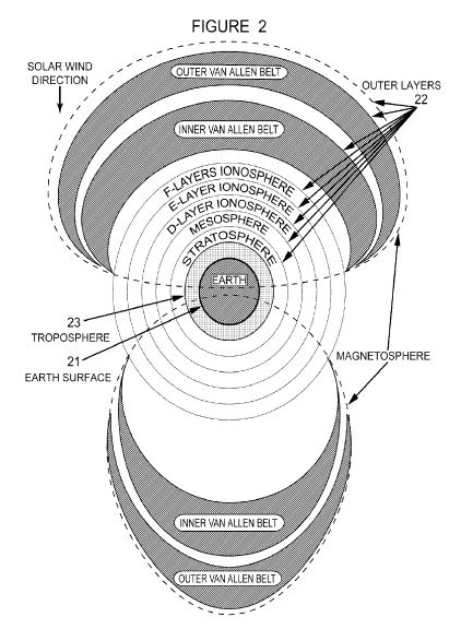
[0003] The term "Earth's Outer Layers" refers to: Earth's Magnetosphere, Van Allen Belts, Ionosphere, Mesosphere, and Stratosphere as illustrated in FIG. 2
[0004] 2. Description of the Prior Art
[0005] One day while reading an old scientific magazine I saw a small article on the research of Dr. John Trump of MIT (the basis for an electrostatic generator patented later by Onezime P. Breaux in U.S. Pat. No. 4,127,804). The article talked about a series of experiments which Dr. Trump had performed with a 2-plate, capacitor in a vacuum dielectric. Briefly, he discovered that by varying the distance between the two plates one could produce current flows in one direction or the other between either of the plates and ground.
[0006] The Solar Wind strikes "Earth's Outer Layers" constantly as do many other cosmic particles. At any given instant of time, the vector product of these impacts produces either a net pressure increase or decrease in the Troposphere. This creates random waves of pressure in the "Earth's Outer Layers" as one charged "plate" moves in relation to the oppositely-charged Earth's surface as the other "plate". This variation of pressure in the "Earth's Outer Layers" is equivalent to moving an outer "plate" back and forth toward the Troposphere and the Earth's surface as the inner "plate"-thus giving rise to variations in voltage on both "plates". In this case the Troposphere (see FIG. 2) acts as the dielectric medium instead of the vacuum in the Trump experiments. Furthermore, the Troposphere, itself, is also compressed and decompressed by these random waves of pressure on the "Earth's Outer Layers". Thus, I reasoned if one could create a charged envelope or field of sufficient voltage within the Troposphere, one could convert these random pressure waves in the dielectric Troposphere into current flow on the Earth's surface.
[0007] As "Earth's Outer Layers" surround the planet, any impact waves propagate throughout all of them when they are present-even to the nighttime side of the planet. Thus, I also reasoned one could extract power from these impacts anywhere on Earth's surface or in its atmosphere whether it be day or night. The pressure waves on the dark side of Earth would be less energetic than those occurring on the daytime side because the nighttime layers of the Ionosphere are compressed so much that the D-Layer of the Ionosphere disappears at night and the F1 and F2-Layers of the Ionosphere combine into one F-Layer. I calculated the available energy from these impact waves would be significantly less by 30-45% depending upon one's location on the night side of the planet in respect to the terminator.
[0008] Many years ago around 1900 Dr Nikola Tesla built and tested a device to extract energy from the Sun using an apparatus which forms part of my own invention (see U.S. Pat. Nos. 685,957 and 685,958 dated 5 Nov. 1901).
[0009] Subsequently, Dr. Thomas Henry Moray, another inventor and student of these Tesla patents made a device which apparently accessed the same source of energy but with a method different than my own. As Dr. Moray was never granted a patent for his device I cannot be certain that his work is considered prior art but I list it here as part of my due diligence. Apparently, he had trouble explaining the source of energy his device was converting to the patent reviewer and was, thus, not granted a patent for his impressive work. Dr. Moray's public disclosure of certain aspects of his invention are public knowledge through his published lectures and his book, "The Sea of Energy in Which the Earth Floats'-published in 1931.
[0010] Since the beginning of the 20th Century mankind has been looking for new sources of electric power to feed the ever-increasing energy demands of the human population. In the last half of the 19th Century coal, whale oil, human and animal labor, moving water, wind and wood were main sources of energy. However, in the first quarter of the 20th Century mankind began to use more electricity produced by hydroelectric generators and other generators producing electricity by combustion of fossil fuels. With increasing use of gasoline engines and the increasing use of electrical appliances the demand for electricity accelerated the addition of heat and greenhouse gases into the Earth's ecosystem.
[0011] In the last half of the 20th Century many forward-thinking individuals began looking for alternate energy sources to reduce the emissions of greenhouse gases. All of the alternate energy systems investigated and/or developed in the last 56 years have had significant drawbacks to their usage as the main energy supply for the needs of humanity.
[0012] Some of those alternate energy systems were nowhere near as efficient as the existing systems. Some of the alternate energy systems still introduced extra heat into the environment like the existing fossil fuel and nuclear energy systems. And, yet, others produced even more greenhouse gases than the existing energy systems. Some of the new systems used food resources to produce combustible fuels which, consequently, reduced the food resources of the planet. Among the leaders in the new energy sources was and is nuclear energy which produces extra heat, toxic wastes and materials which can be used in nuclear weapons. Hydroelectric energy sources do not add heat to the ecosystem but they are not an inexhaustible resource as they depend upon rainfall which is diminishing as global warming increases. Wind energy resources do not add heat to the ecosystem but they are not constant and require expensive conversion and storage equipment.
[0013] The ideal energy source for mankind will not add heat to the planet's ecosystem, will not produce by-product green house gases; will not deplete our food and water resources; will not produce toxic wastes; however, it will be portable, self-replenishing and constantly available in real time anywhere on Earth and in useful quantities.
[0014] Our major source of natural energy on Earth is the Sun. Energy from the Sun enters the Earth's ecosphere by particle bombardment, radiated electromagnetic energy, gravitational variations and magnetic processes. Mankind has developed various methods of capturing energy from the Sun already. Silicon-based solar cells convert light in a narrow bandwidth into electron flows. These cells are-at most-only 50% efficient and only work when the Sun is shining on them and at an optimum angle. Wind turbines only work when there is wind to power them and are-for the most part-not portable. Devices to convert wave action in the oceans only work when there are waves created by the wind and tidal effects caused by gravitational variations; and they are not portable enough to be used in common transportation devices.
[0015] I concluded if mankind could find an inexpensive method of obtaining electricity from the Sun in some form that worked both day and night and which was already flowing into the Earth's ecosystem, we might be able to develop a clean and self-replenishing energy source which would add no extra heat to our ecosystem, would not alter our planetary albedo and might well be made in a portable form.
SUMMARY OF THE INVENTION
[0016] The Harmonic Energy Exchange Device (or "HEED") offers an interim solution to Earth's dwindling fossil fuel resources. It utilizes a previously untapped energy resource which exists throughout the known Universe. By the very nature of the invention, it only interrupts the flow of energy from the Sun and all the other cosmic sources of high-energy particles on their normal journey to the Earth by way of The Outer Layers.
[0017] The invention does not add energy to the normal thermodynamic equilibrium of the planet and its associated outer layers. The invention does not produce wastes-toxic or otherwise. It does not produce harmful gases; and in some embodiments it could even assist in the rebuilding of our thinning ozone shield. Use of this invention will eventually remove mankind's dependence on fossil fuels and create new occupations. It will be cheap enough that homeowners will be able to install their own HEED and sell back energy to the grid until such time as every home has their own HEED and civilization has completely weaned itself from the use of fossil fuels and nuclear energy in its current form.
BRIEF DESCRIPTION OF DRAWING
[0018] FIG. 1: Is the preferred embodiment of the circuit diagram of my invention incorporating references to external stimuli which are used to activate the circuit. It represents a parallel tuned circuit to store the energy.
[0019] FIG. 2: Is an illustration of the Earth and it immediate environment as a global capacitor where The Outer Layers form one plate and the Earth's surface form the other plate and both are separated by the Troposphere as a dielectric medium.
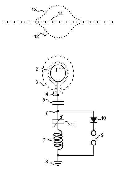
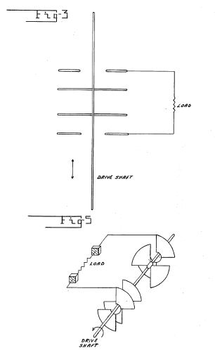
[0020] FIG. 3: Is an alternate embodiment of the circuit diagram of my invention incorporating references to external stimuli which are used to activate the circuit. It represents the use of a series tuned circuit to store the energy.
DETAILED DESCRIPTION OF A PREFERRED EMBODIMENT OF THE INVENTION
[0021] Be it known that I, Harold Stanley Deyo, Jr, a citizen of both The United States of America and The Commonwealth of Australia, residing in the community of Pueblo West in Pueblo County, Colorado have invented an Harmonic Energy Exchange Device which converts dynamic pressures in the ambient media around Earth to controlled electric currents.
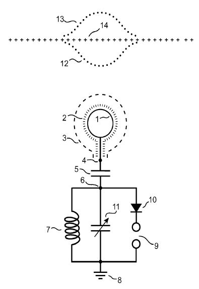
[0022] This invention as represented in FIG. 1 is unique in that it is designed to extract electricity from random pressure waves propagated in the Troposphere 14 by impacts of the solar wind and other cosmic particles with the Earth's "The Outer Layers" 22 of FIG. 2.
[0023] In FIG. 1, the Troposphere 14 in its rest state is represented by the line of "+" marks 14. The convergent or compression state 12 of the random waves in the Troposphere 14 is represented by the lower line of dots while the divergent or decompression state 13 of the random waves in the Troposphere 14 is represented by the upper line of dots. The preferred embodiment of my invention FIG. 1 is a method of coupling a parallel, resonant, electrical circuit to these random pressure waves to extract electricity from them.
[0024] As Dr John Trump's research and Onezime P. Breaux's U.S. Pat. No. 4,127,804 show, when one plate of a charged capacitor is moved closer to or farther from the other plate of that capacitor a voltage change appears on both plates of that capacitor. Furthermore, the electric field gradient between those plates changes as the plates are moved in this manner. Thus they have described a method of converting mechanical energy into electrical current by simply varying the plate spacing over time which can be expressed as ds/dt where "ds" is the change in spacing and "dt" is the change in time.
[0025] As illustrated in FIG. 2, The Outer Layers can be viewed as one plate of a capacitor comprised of the Earth's surface itself as one plate 21 and Earth's outer layers as the other plate 22 where the Earth's Troposphere 23 serves as the dielectric medium separating the two plates. There is a charge between these plates which varies extremely rapidly but not with a constant period. At any given instant, the vector product of all the impacts by the cosmic particles with The Outer Layers 22 will create a pressure wave in The Outer Layers 22 which will manifest in the Troposphere 23. Whatever that vector product is, it will alter the field gradient in the dielectric Troposphere 23. That alteration will either increase or decrease the effective spacing between "plates" 22 and 23.
[0026] In order to capture and convert the resulting voltage variations produced at or near the Earth's surface 21 of FIG. 2, this invention creates its own, localized stress field 3 of FIG. 1 established in the Troposphere 23 of FIG. 2 with a charged, conductive surface 1 of FIG. 1 which is encased in high-voltage insulation 2 of FIG. 1 and extending into the Troposphere 23 of FIG. 2.
[0027] In FIG. 1, a series of high-voltage, starting pulses is applied across points 4 and 6 on opposite sides of a capacitor 5 to create the localized stress field 3. As these high-voltage starting pulses are applied, the parallel resonant circuit formed by inductor coil 7 and variable capacitor 11 both referenced to ground 8 is stimulated into resonance within the bandwidth determined by the values of these circuit components. Tuning of this circuit is effected through variable capacitor 11. The high voltage charge on conductive surface 1 of FIG. 1 is maintained by the parallel tuned circuit formed by inductor coil 7 and variable capacitor 11.
[0028] Then as the random, pressure waves propagate throughout the Troposphere 23 of FIG. 2, the localized stress field 3 of FIG. 1 is oscillated by the compression wave front 12 and the decompression wave front 13-both of FIG. 1 which creates voltage changes on capacitor 5.
[0029] In FIG. 1, the resulting voltages changes on capacitor 5 will add energy to the parallel resonant circuit formed by inductor coil 7 and variable capacitor 11 which acts as a tank circuit to store the energy which has been passed to it. As energy builds in the parallel circuit the voltage of the circuit rises until a spark discharge occurs across the gap 9 also referenced to ground 8. The current will only discharge in one direction as determined by diode 10. The circuit will work without diode 10 but a diode is used here as one method to keep from draining all the energy from the tank circuit when a discharge occurs.
[0030] This resonant circuit can be tuned to various bandwidths to maximize the efficiency of the conversion process depending upon location of the device, time of day, temperature variations, relative humidity and other variables in the ambient Troposphere 23 of FIG. 2 around the conductive surface 1 of FIG. 1. A resistive load to extract power from the resonant circuit can be used instead of the spark gap 9 of FIG. 1.
[0031] This preferred embodiment uses a parallel, tuned circuit to access a wide range of frequencies usually to be found in the range of 4.5 to 7 MHz. This range encompasses the major, naturally-occurring, resonant frequencies found in the ionosphere.
[0032] A second embodiment of this invention as shown in FIG. 3 replaces the parallel tuned circuit formed by inductor coil 7 and variable capacitor 11 in FIG. 1 placed in parallel to each other and referenced to ground 8 in FIG. 1. This second embodiment forms a series tuned circuit formed by inductor coil 7 and variable capacitor 11 in FIG. 3 placed in series to each other and referenced to ground 8 of FIG. 3. It differs from the preferred embodiment only in the placement of variable capacitor 11 of FIG. 3 so that it is in series with coil 7 of FIG. 3.
[0033] This embodiment limits the frequency range and, hence, the energy the system will store when compared to the preferred embodiment. It produces higher voltages across the spark gap 9 of FIG. 3 than those produced in the preferred embodiment across the spark gap 9 of FIG. 1.
US4127804
Electrostatic energy conversion system
Inventor(s):
BREAUX ONEZIME, et al.Electrostatic energy conversion system
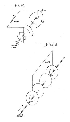
Two inversely ganged variable capacitors having a common movable element varying the capacities such that when one capacitor is at maximum capacitance, the other is at minimum capacitance, have, after initially charging, a substantially constant contained or trapped charge distributed between the two capacitors. As the capacities of the capacitors are varied, a potential difference is developed between the fixed plate of one capacitor and the fixed plate of the other. When these two potential points are connected to a load, charge is transferred from one capacitor to the other as a current flow through the load. The total charge is not diminished, the energy supplied the load being the energy expanded on moving the movable charged plates. As the movable plates are moved in a cyclic manner an alternating current is provided to the load.
BACKGROUND OF THE INVENTION
The field of the invention is in electrostatic machines.
Electrostatic machines have been well known for many years. The Toepler-Holtz and the Wimshurst machines were early electrostatic generators. Now their usage is mainly for demonstrations in the Physics Laboratory. The only remaining electrostatic machine to remain in extensive usage is the Van de Graaff type electrostatic generator. It is presently used to generate extremely high voltage potentials for atomic research. Substantially all of the prior art devices are direct current type machines.
The following publications may be helpful in further understanding the art. Electrostatic Sources of Electric Power, John G. Trump, Electrical Engineering, Vol. 66, No. 6, June 1947, pages 525-534; U.S. Pat. No. 2,810,878 to patentee N. Felici, and U.S. Pat. No. 3,094,653 to patentees D. B. LeMay et al.
http://www.tesla.svensons.com/?US000685957
US685957
Apparatus for the Utilization of Radiant Energy
Nikola
TeslaApparatus for the Utilization of Radiant Energy
It is well known that certain radiations such as those of ultra-violet light, cathodic, Roentgen rays, or the like possess the property of charging and discharging conductors of electricity, the discharge being particularly noticeable when the conductor upon which the rays impinge is negatively electrified. These radiations are generally considered to be ether vibrations of extremely small wave lengths, and in explanation of the phenomena noted it has been assumed by some authorities that they ionize or render conducting the atmosphere through which they are propagated. My own experiments and observations, however, lead me to conclusions more in accord with the theory heretofore advanced by me that sources of such radiant energy throw off with great velocity minute particles of matter which are strongly electrified, and therefore capable of charging an electrical conductor, even if not so, may at any rate discharge an electrified conductor either by carrying off bodily its charge or otherwise.
My present application is based upon a discovery which I have made that when rays or radiations of the above kind are permitted to fall upon an insulated conducting-body connected to one of the terminals of a condenser while the other terminal of the same is made by independent means to receive or to carry away electricity a current flows into the condenser so long as the insulated body is exposed to the rays, and under the conditions hereinafter-specified an indefinite accumulation of electrical energy in the condenser takes place. This energy after a suitable time interval, during which the rays are allowed to act, may manifest itself in a powerful discharge, which maybe utilized for the operation or control of mechanical or electrical devices or rendered useful in many other ways.
In applying my discovery I provide a condenser, preferably of considerable electrostatic capacity, and connect one of its terminals to an insulated metal plate or other conducting-body exposed to the rays or streams of radiant matter.
It is very important, particularly in view of the fact that electrical energy is generally supplied at a very slow rate to the condenser, to construct the same I use, by preference, the best quality of mica as dielectric, taking every possible precaution in insulating the armatures, so that the instrument may withstand great electrical pressures without leaking and may leave no perceptible electrification when discharging instantaneously. In practice I have found that the best results are obtained with condensers treated in the manner described in a patent granted to me February 23,1897, No. 577,671. Obviously the above precautions should be the more rigorously observed the slower the rate of charging and the smaller the time interval during which the energy is allowed to accumulate in the condenser. The insulated plate or conducting-body should present as large a surface as practicable to the rays or streams of matter, having ascertained that the amount of energy conveyed to it per unit of time is under otherwise identical conditions proportionate to the area exposed, or nearly so. Furthermore, the surface should be clean and preferably highly polished or amalgamated. The second terminal or armature of the condenser may be connected to one of the poles to any conducting body or object whatever of such properties or so conditioned that by its means electricity of the required sign will be supplied to the terminal. A simple way of of a battery or other source of electricity generally convey a positive charge to the first condenser-terminal, which is connected to the plate or conductor above mentioned, I usually connect the second terminal of the condenser to the ground, this being the most convenient Way of obtaining negative electricity, dispensing with the necessity of providing an artificial source. In order to utilize for any useful purpose the energy accumulated in the condenser, I furthermore connect to the terminals of the same circuit including an instrument or apparatus which it is desired to operate and another instrument or device for alternately closing and opening the circuit. This latter may be any form of circuit-controller, with fixed or movable parts or electrodes, which may be actuated either by the stored energy or by independent means,
My discovery will be more fully understood from the following description and annexed drawings, to which reference is now made, and in which Figure 1 is a diagram showing the general arrangement of apparatus as usually employed. Fig. 2 is a similar diagram illustrating more in detail typical forms of the devices or elements used in practice, and Figs. 3 and are diagrammatical representations of modified arrangements suitable for special purposes.
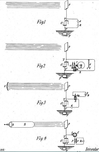
As illustrative of the manner in which the several parts or elements of the apparatus in one of its simplest forms are to be arranged and connected for useful operation, reference is made to Fig. 1, in which 0 is the condenser, P the insulated plate or conducting-body which is exposed to the rays, and P another plate or conductor which is grounded, all being joined in series, as shown. The terminals T of the condenser are also connected to a circuit which includes a device R to be operated and a circuit-controlling device d of the character above referred to.
The apparatus being arranged as shown, it will be found that when the radiations of the sun or of any other source capable of producing the effects before described fall upon the plate P an accumulation of electrical energy in the condenser C will result. This phenomenon, I believe, is best explained as follows: The sun, as well as other sources of radiant energy, throws off minute particles of matter positively electrified,which,impinging upon the plate P, communicate continuously an electrical charge to the same. The opposite terminal of the condenser being connected to the ground, which may be considered as a vast reservoir of negative electricity, a feeble current flows continuously into the condenser, and inasmuch as these supposed particles are of an inconceivably small radius or curvature, and consequently charged to a relatively very high potential, this charging of the condenser may continue, as I have actually observed, almost indefinitely, even to the point of rupturing the dielectric. If the device be of such character that it will operate to close the circuit in which it is included when the potential in the condenser has reached a certain magnitude, the accumulated charge will pass through the circuit, which also includes the receiver R, and operate the latter.
In illustration of a particular form of apparatus which may be used in carrying out my discovery I now refer to Fig. 2. In this figure, which in the general arrangement of the elements is identical to Fig. 1, the device at is shown as composed of two very thin conducting-plates 2ft, placed in close proximity and very mobile, either by reason of extreme flexibility or owing to the character of their support. To improve their action,they should be inclosed in a receptacle, from which the air may be exhausted. The plates 25 are connected in series with a working circuit, including a suitable receiver, which in this case is shown as consisting of an electromagnet M, a movable armature a, a retractile spring, and a ratchet-wheel 10, provided with a spring-pawl 1 which is pivoted to armature a, as illustrated. When the radiations of the sun or other radiant source fall upon plate P, a current flows into the condenser, as above explained, until the potential therein rises sufficiently to attract and bring into contact the two plates 25 t, and thereby close the circuit connected to the two condenser-terminals. This permits a fiow of current which energizes the magnet M, causing it to draw down the armature a and impart a partial rotation to the ratchet-Wheel to. As the current ceases the armature is retracted by the spring, without, however, moving the wheel. With the stoppage of the current the plates t t cease to be attracted and separate, thus restoring the circuit to its original condition.
Fig. 3 shows a modified form of apparatus used in connection with an artificial source of radiant energy, which in this instance may be an arc emitting copiously ultra-violet rays. A suitable reflector may be provided for concentrating and directing the radiations. A magnet and circuit-controller d are arranged as in the previous figures; but in the present case the former instead of performing itself the whole work only serves the purpose of alternately opening and closing a local circuit, containing a source of current B and a receiving or translating device D. The controller, if desired, may consist of two fixed electrodes separated by a minute air gap or weak dielectric film, which breaks down more or less suddenly when a definite difference of potential is reached at the terminals of the condenser and returns to its original state upon the passage of the discharge.
Still another modification is shown in Fig. 4, in which the source S of radiant energy is a special form of Roentgen tube, having but one terminal 70, generally of aluminium, in the form of half a sphere,with a plain polished surface on the front side, from which the streams are thrown off. It may be excited by attaching it to one of the terminals of any generator of sufficiently high electromotive force; but whatever apparatus be used it is important that the tube be exhausted to a high degree, as otherwise it might prove entirely ineffective. The working or discharge circuit connected to the terminals T T of the condenser includes in this case the primary 19 of a transformer and a circuit controller comprising a fixed terminal or brush t and a movable terminal 25 in the shape of a wheel, with conducting and insulating segments, which may be rotated at an arbitrary speed by any suitable means. In inductive relation to the primary wire or coil 19 is a secondary s, usually of a much greater number of turns, to the ends of which is connected a receiver R. The terminals of the condenser being connected, as indicated, one to an insulated plate P and the other to a grounded plate P, when the tube S is excited rays or streams of matter are emitted from the same, which convey a positive charge to the plate P and condenser-terminal T, while terminal T is continuously receiving negative electricity from the plate P. This, as before explained, results in an accumulation of electrical energy in the condenser, which goes on as long as the circuit including the cult is closed owing to the rotation of the terminal t, the stored energy is discharged through the primary 19, this giving rise in the energy, comprising in combination, a condenser, secondaries to induced currents, which oper ate the receiver R.
It is clear from what has been stated above that if the terminal T is connected to a plate supplying positive instead of negative electricity the rays should convey negative electricity to plate P. The source S maybe any form of Roentgen or Lenard tube; but it is theory of action that in order to be very effective the electrical impulses exciting it should be wholly or at least preponderately of one sign. If ordinary symmetrical alternating currents are employed, provision should be made for allowing the rays to fall upon the plate P only during those periods when they are productive of the desired result. Evidently if the radiations of the source be stopped or intercepted or their intensity varied in any manner,as by periodically interrupting or rhythmically varying the current exciting the source, there will be corresponding changes in the action upon the receiver R, and thus signals may be transmitted and will respond to or be set in operation when a predetermined amount of energy is stored in the condenser may be used in lieu of the device specifically described with reference to Fig. 2
US685958
Method of Utilizing Radiant Energy
Nikola
TeslaMethod of Utilizing Radiant Energy
It is well known that certain radiations such as those of ultra-violet light, cathodic, Roentgen rays, or the like possess the property of charging and discharging conductors of electricity, the discharge being particularly noticeable when the conductor upon which the rays impinge is negatively electrified. These radiations are generally considered to be ether vibrations of extremely small wavelengths, and in explanation of the phenomena noted it has been assumed by some authorities that they ionize or render conducting the atmosphere through which they are propagated. My own experiments and observations, however, lead me to conclusions more in accord with the theory heretofore advanced by me that sources of, such radiant energy throw with great velocity minute particles of matter which are strongly electrified, and therefore capable of charging an electrical conductor, or even if not so may at any rate discharge an electrified conductor either by carrying bodily its charge or otherwise.
My present application is based upon a discovery which I have made that when rays or radiations of the above kind are permitted to fall upon an insulated conducting body connected to one of the terminals of a condenser, while the other terminal of the same is made by independent means to receive or to carry away electricity, a current flows into the condenser so long as the insulated body is exposed to the rays, and under the conditions hereinafter specified an indefinite accumulation of electrical energy in the condenser takes place. This energy after a suitable time interval, during which the rays are allowed to act, may manifest itself in a powerful discharge, which may be utilized for the operation or control of mechanical or electrical devices or rendered useful in many other ways.
In applying my discovery I provide a condenser, preferably of considerable electrostatic capacity, and connect one of its terminals to an insulated metal plate or other conducting body exposed to the rays or streams of radiant matter. It is very important,particularly in view of the fact that electrical energy is generally supplied at a very slow rate to the condenser, to construct the same with the greatest care. I use by preference the best quality of mica as dielectric, taking every possible precaution in insulating the armatures, so that the instrument may withstand great electrical pressures without leaking and may leave no perceptible electrification when discharging instantaneously. In practice I have found that the best results are obtained with condensers treated in the manner described in a patent granted to me February 23, 1897, No. 577,671. Obviously the above precautions should be the more rigorously observed the slower the rate of charging and the smaller the time interval during which the energy is allowed to accumulate in the condenser. The insulated plate or conducting body should present as large a surface as practicable to the rays or streams of matter, I having ascertained that the amount of energy conveyed to it per unit of time is under otherwise identical conditions proportionate to the area exposed, or nearly so. Furthermore, the surface should be clean and preferably highly polished or amalgamated. The second terminal or armature of the condenser may be connected to one of the poles of a battery or other source of electricity or to any conducting body or object whatever of such properties or so conditioned that by its means electricity of the required sign will be supplied to the terminal. A simple way of supplying positive or negative electricity toy the terminal is to connect the same either to an insulated conductor, supported at some height in the atmosphere, or to a grounded conductor, the former, as is well known, furnishing positive and the latter negative electricity. As the rays or supposed streams of matter generally convey a positive charge to the first condenser-terminal,which is connected to the plate' or conductor above mentioned, I usually connect the second terminal of the condenser to the ground, this being the most convenient Way of obtaining negative electricity, dispensing with the necessity of providing au artificial source. In order to utilize for any useful purpose the energy accumulated in the condenser, I furthermore connect to the terminals of the same a circuit including an instrument or apparatus which it is desired to operate and another instrument or device for alternately closing and opening the circuit. This latter maybe any form of circuit-controller, with fixed or movable parts or electrodes, which may be actuated either by the stored energy or by independent means.
The rays or radiations which are to be utilized for the operation of the apparatus above described in general terms may be derived from a natural source, as the sun, or may be artificially produced by such means, for example, as an arc-lamp, a Roentgen tube, and the like, and they may be employed for a great variety of useful purposes.
My discovery will be more fully understood from the following detailed description and annexed drawings, to which reference is now made, and in which Figure 1 is a diagram showing typical forms of the devices or elements as arranged and connected in applying the method for the operation of a mechanical contrivance or instrument solely by the energy stored; and Fig. 2 is a diagrammatical representation of a modified arrangement suitable for special purposes, with a circuit-controller actuated by independent means.
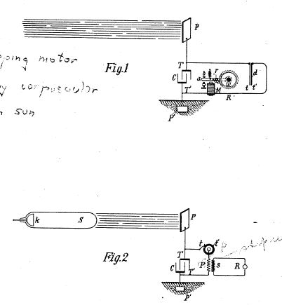
Referring to Fig. l, O is the condenser, P the insulated plate or conducting body, which is exposed to the rays, and P another plate or conductor, all being joined in series,as shown. The terminals T T of the condenser are also connected to a circuit including a receiver R, which is to be operated, and a circuit-controlling device which in this case is composed of two very thin conducting plates t t', placed in close proximity and very mobile, either by reason of extreme flexibility or owing to the charater of their support. To improve their action, they should be inclosed in a receptacle from which the air may be exhausted. The receiver R is shown as consisting of an electromagnet M, a movable armature a, a retractile spring b, and a ratchet-wheel w, provided with a spring-pawl r, which is pivoted to armature a, as illustrated. The apparatus being arranged as shown, it will be found that when the radiations of the sun or of any other source capable of producing the effects before described fall upon the plate P an accumulation of electrical energy in the condenser C will result.
This phenomenon, I believe, is best explained as follows: The sun as well as other sources of radiant energy throw off minute particles of matter positively electrified, which, impinging upon the plate P, communicate an electrical charge to the same. The opposite terminal of the condenser being connected to the ground, which may be considered as a vast reservoir of negative electricity, a feeble current flows continuously into the condenser, and inasmuch as these supposed particles are of an inconceivably small radius or curvature, and consequently charged to a relatively very high potential, this charging of the condenser may continue, as I have found in practice, almost indefinitely, even to the point of rupturing the dielectric. Obviously whatever circuit controller be employed it should operate to close the circuit in which it is included. Thus in Fig. when the electrical pressure at the terminals T T' rises to a certain predetermined value the plates t t', attracting each other, close the circuit connected to the terminals. This permits a flow of current which energizes the magnet M, causing it to draw down the armature a and impart a partial rotation to the ratchet-wheel w. As the current ceases the armature is-retracted by the spring b without, however, moving the wheel w. With the stoppage of the current the condenser has reached the desired magnification the plates t t" cease to be attracted and separate, thus restoring the circuit to its original condition.
Many useful applications of this method of utilizing the radiations emanating from the sun or other source and many ways of carrying out the same will at once suggest themselves from the above description. By way of illustration a modified arrangement is shown in Fig. 2, in which the source S of radiant energy is a special form of Roentgen tube devised by me having but one terminal k, generally of aluminium, in the form of half a sphere with a plain polished surface on the front side, from which the streams are thrown. It may be excited by attaching it to one of the terminals of any generator of sufficiently high electromotive force; but whatever apparatus be used it is important that the tube be exhausted to a high degree, as otherwise it might prove entirely ineffective. The working or discharge circuit connected to the terminals T T of the condenser includes in this case the primary p of a transformer and a circuit-controller comprising a fixed terminal or brush t and a movable terminal t' in the shape of a wheel with conducting and insulating segments which may be rotated at an arbitrary speed by any suitable means. In inductive relation to the primary wire or coil p is a secondary s, usually of a much greater number of turns, to the ends of which is connected a receiver R. The terminals of the condenser being connected as indicated, one to an insulated plate P and the other to a grounded plate P', when the tube S is excited rays or streams of matter are emitted from the same, which convey a positive charge to the plate P and condenser terminal T, while terminal T' is continuously receiving negative electricity from the plate P'. This, as before explained, results in an accumulation of electrical energy in the condenser, which goes on as long as the circuit including the primary p is interrupted. Whenever the circuit is closed, owing to the rotation of the terminal t', the stored energy is discharged through the primary p, this giving rise in the secondary s to induced currents which operate the receiver R. It is clear from what has been stated above that if the terminal T is connected to a plate supplying positive instead of negative electricity the rays should convey negative electricity to plate P. The source S may be any form of Roentgen or Lenard tube; but it is obvious from the theory of action that in order to be very effective the electrical impulses exciting it should be wholly or at least preponderatingly of one sign. If ordinary symmetrical alternating currents are employed, provision should be made for allowing the rays to fall upon the plate P- only during those periods when they are productive of the desired result. Evidently if the radiations of the source be stopped or intercepted or their intensity varied in any manner, as by periodically interrupting or rhythmically varying the current exciting the source, there will be corresponding changes in the action upon the receiver R, and thus signals may be transmitted and many other useful effects produced. Furthermore,it will be understood that any form of circuit-closer which will respond to or be set in operation when a predetermined amount of energy is stored in the condenser may be used in lieu of the device specifically described with reference to Fig. l, and also that the special details of construction and arrangement of the several parts of the apparatus maybe very greatly varied without departure from the invention.
https://www.youtube.com/watch?v=QCa8mpPD680
Radiant
Energy Circuits - Tesla 1901 - Patent No. 685958
My test results for 2 months on the basic concept. Special thanks to all those who pushed forward towards harnessing natural (radiant) energy. YouTube squashed my first release of this video after getting almost 6k views, a bunch of likes and comments after only 5 days... guess YouTube doesn't like anyone posting stuff about this lost patent...
http://www.tesla-coil-builder.com/Articles/TeslasRadiationsAndCosmicRays01.pdf