Summary
: Odic Activity
Electricity is not only a force, but a substance; Amperage is the substance ( infinitely small eddies of force ), and Voltage is the speed.
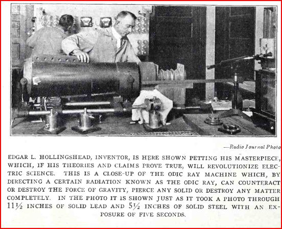
The Odic Ray changes the weight of metal... explodes hard clay... makes rock transparent... penetrates lead to take photographs... application to metal renders it permanently cold... decomposes water to H & O...
There are 3 phases in all forces: Dominant Third, Negative, and Dominant or Solar at definite distances apart in speed. Their relationship is 3:6:9.
All forces actually are two forces in one : rectilinear and rotating.
The rotational force can be broken and released. This is called "Odic Activity".
The rate of Odic Activity can be changed, its polarity can be reversed, and the direction of its discharge can be controlled.
The only difference between one ray and another is in speed, and possibly in polarity or character. The Odic Ray can be altered to duplicate any known rays or rate of force known, such as light, X-rays, UV rays, etc.
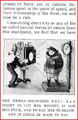
Physical weight depends on the speed of rotation of substance particles, which resists the force of gravity. The Odic Ray can reduce or increase the speed of substance rotation, thus decreasing or increasing its weight reversibly. Thus the weight of objects depends upon atomic forces, not physical properties.
The methods used by Ernst W. Keely would seem to apply here. Nikola Tesla also praised the 3:6:9 ratio...
Radio-Journal, Vol. 2, p. 240 ( May 1923 )
The Odic Ray, Its Origin and Nature
http://www.amazon.com/Triune-Brotherhood-Project-Its-Message/dp/B000NUZBQK/ref=s%5Cr_1_10?s=books&ie=UTF8&qid=1370304826&sr=1-10
"Triune Brotherhood Project and Its Message To You : The Triune Brotherhood and How it Is Proposed to Use a Rediscovered Ancient Process Known as the Odic Ray To Establish a Great Movement for the Uplift of Mankind - by Edgar L Hollingshead (Author)"
Publisher: Self Published (1931)
http://blog.modernmechanix.com/are-x-rays-outclassed-by-powerful-new-odic-ray/
Popular Science ( March 1922 )

Are
X-Rays Outclassed by Powerful New “Odic Ray”?
DISCOVERY of “odic rays” of high penetration produced simply by the electric current drawn from an ordinary light socket, and yet with the curative and medicinal value of X-rays, is claimed by Dr. Edgar L. Hollingshead, of Pasadena, Calif.
With simple, inexpensive apparatus he is reported to have passed rays through 11-1/2 inches of lead and 4-1/2 inches of steel, at such strength as to sear dental X-ray films encased in tinfoil.
Such an achievement appears impossible; yet X-rays seemed equally impossible when Rontgen first announced their discovery. Doctor Hollingshead’s claims are based on tests made in the presence of eyewitnesses who selected at random the films exposed to the rays, retained the duplicates, and developed the two simultaneously in the presence of an unprejudiced committee. After exposure, these films were found to be perceptibly darkened.
Doctor Hollingshead declares that the rays produced try his apparatus are of greater intensity and penetration than any previously known to science. The rate of vibration of the “odic rays” can be controlled by the operator, it is asserted. If these claims are substantiated, the value of the discovery to the world will be enormous. The medical profession will have an unlimited supply of curative rays. The X-ray diagnosis can be utilized by every doctor in the country, since the apparatus can readily be carried from house to house. The doctor has given a partial explanation of his ray.
He has found, he says, that electricity is not simply a force, but a substance. Amperage, he adds, is the substance part of electricity and voltage the speed. Like any other substance, electricity is composed of vibrating molecules, atoms, electrons, and other infinitesimal units, and the form that the substance takes is due to the rates of atomic speed.
The only differences between one ray of light and another are in wave lengths or vibration, speed of discharge, and polarity. Assuming that electricity is like water flowing through a pipe, and that its voltage is the speed with which it travels, he first intensifies its atomic speed, then he breaks it up, releasing a force or ray of great speed and power.
http://books.google.com/books?id=hlUcAQAAMAAJ&pg=PA57&lpg=PA57&dq=Edgar+Hollingshead+odic+ray&source=bl&ots=UK4zh2QQh2&sig=2vakCossjZm7iFtVc4uQvpy75Y0&hl=en&sa=X&ei=bzOUUc-KJoOKjAK6lICwCA&ved=0CEAQ6AEwBA#v=onepage&q=Edgar%20Hollingshead%20odic%20ray&f=false
Engineering and Mining Journal, Volume 112
Lighter Than Air
A discovery so marvelous that it makes Peruna look like a soft drink has been reported from Seattle. it is that of the so-called "odic-activity ray" and is credited to Prof. Edgar L. Hollingshead, if we may believe all that we read. The principle of the thing is ridiculously simple. This ray makes heavy things light, to as great a degree as any one may wish. The idea is not exactly new, as more than one Jules Verne has conceived of a force that would counter and then overcome that of gravitation. it is predicted that steel vessels of the air will this be made as light as bubbles. Imagine Dempsey and Carpenter each with a chunk of this ray in his shoes. It would be better than fighting on the moon. Then again, talking of fighting, the ray would make newlyweds' biscuits lighter than seafoam, and lastly, flotation would be backed off the map. Where would Minerals Separation be then, poor thing!
http://www.ebooksread.com/authors-eng/ernest-jack-stevens/vibrations-their-principles-light-and-colors-their-uses-essays-lessons-hea-ala/page-6-vibrations-their-principles-light-and-colors-their-uses-essays-lessons-hea-ala.shtml
Ernest Jack Stevens : Vibrations, their principles; light and colors, their uses
ODIC-ACTIVITY RAYS
The odic-activity ray, more powerful than the X-ray or the) radium ray, is to completely conquer the air.
The giant sky liner, safe as any conveyance ever perfected, equal in luxury and comfort to the palatial greyhounds of the ocean lanes, is a posiibilty and probability of the near future.
These were the announcements made by Prof. Edgar L. Hollingshead, scientist of Pasadena, in an exclusive interview in May, 1921.
For, he declares, this powerful ray will make metals so light that a huge steel sky ship would become light as a bubble.
Not only this, but the odic-activity ray, Prof. Hollingshead claims, will take the place of radium, valued at $120,000 a gram, and revolutionize the scientific world in the treatment of certain diseases.
And the cost of Lightening metals, of using the rays for medical purposes, is so minute as to be almost negligible.
The odic-activity ray, according to Prof. Hollingshead, so far has successfully changed the weight of metal over 100 times in as many tests; it has caused hard clay to explode the instant the ray touched it; rock, opaque to the eye, has been made transparent and by means of the ray, an actual photograph has been taken through a solid sheet of lead. One application of the ray on metal has caused it to become permanently cold beyond the possibility of ever becoming heated. And it has instantly changed water into its primary gases hydrogen and oxygen.
Syracuse ( NJ ) Journal ( January 3, 1922 )
Missile
From This Gun Laughs At Nature's Laws

The missile is the so-called Odic Activity Ray which Hollingshead asserts he has been able to focus and direct with astonishing results. it is capable, he says, of disturbing the fundamental physical organization of our known universe, and may be employed in a commercial or military way.
What It Will Do
Although still in the experimental phase, the "Ray Gun" to the satisfaction of Hollingshead and his associates, has demonstrated that:
The weight of any base metal may be instantly changed by being subjected to the Odic-Activity Ray.
Ordinary rock can be made transparent.
Mater can be made to disintegrate without explosion, vanishing without ash, smoke or residue.
Water may be instantly transformed into its component elements.
A piece of metal may be given more lifting power than any gas without losing its tensile strength.
Nature's so-called immutable laws can be broken down by changing the atomic speed of matter.
Hollingshead, for 15 years a physicist, says of his theories and experiments with the Odic-Activity Ray:
"Ten years ago I came to the conclusion that matter did not depend upon physical prperties for its weight, but that weight is determined by the atomic speed of matter.
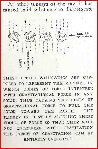
"It is accepted as fact that matter is an aggregation of molecules. Now, molecules are eddies of force, traveling in circular progression. These in turn are formed of still tinier particles similarly in motion, called atomic speed. Atoms are composed of electrons and ions, which have been split up and found to be composed of still smaller particles.
"I concluded, therefore, that there is no such thing as a solid, but that what we call a solid is in reality a seething mass of whirling force.
"The only way in which force can manifest itself is through resistance to other force, principally gravity -- which we call weight.
"Gravitation is force coming from the sun; the negative,levitation, is force returned from earth to sun. The weight of an object is the degree of resistance matter imposes in the path of these two forces, and the degree of resistance in turn is dependent upon the speed of the circular eddies of force of which matter is composed.
"My experiments have been to find a way of generating force that would alter the speed of these whirls called matter so that i could change its degree of resistance to either gravitation or levitation and thus its weight. the result is the Odic Activity Ray which I have generated and which has greater possibilities than any other ray known.
The Odic Activity Ray will affect a photographic plate or disintegrate matter, depending upon the wave length, which can be altered -- all rays known to man being between these two extremes. It can be directed and focused, something which has not been done with x-rays.
"It has been generated to penetrate 16 inches of metal, and yet not harm the hand that encircles it.
"The main aim of our experiments was to change the wright of metal, and this I have done to my satisfaction, if not yet publicly. We have decreased the weight of aluminum, for instance, 20 per cent; then made it heavier than normal. And every base metal has responded to some degree, the change being instantaneous and permanent until again treated."
CA145749
Armature for Dynamos
( 2-4-1913 )
Edgar L. Hollingshead
Armature for Dynamos
( 2-4-1913 )
Edgar L. Hollingshead
My invention relates to improvements in Armatures for Dynamo Electric Machines of which the following is a specification.
Its object is to provide an armature core that will act upon the lines of the magnetic field in which the core rotates in such a manner as to reduce the tendency of sparking at the commutator when working under overload and to allow the reversal of motor machines without the imterposition of the starting box between the power line and the machine.
My construction reduces the heating effect in the armature core and the result of danger of burning out the insulation of electrical conducctors.
In the drawings with which I have illustrated my device and which form part of this specification,
Fig. 1 is a side elevation of a motor equipped with my form of armature;
Fig. 2 is an elevation illustrating the commutators on the armature;
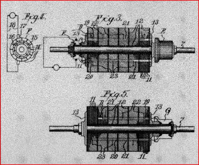
Fig. 3 is a sectional view of the armature;
Fig. 4 is an end view of the core commutator on the armature showing the brush connection, and
Fig. 1.5 is a sectional view of an alternative construction of my armature in which the core commutator is combined with the regular commutator of the armature.
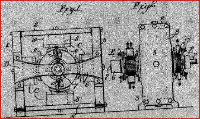
The frame B may be of any ordinary construction but is preferably formed of a series of sections or parts joined together to make up magnetic conductors in the magnetic circuits of the machine. Top and bottom parts 2 and 3 are connected to the parts 4 and 5 to which are attached brackets 6 forming journal supports for the shaft 7 of the armature. The parts B and 3 are preferably made up of soft magnetic permeable iron while the sides 4 and 5 are made up of hard impermeable iron. The poles C are formed with a soft iron core 8, a hard iron tip 9 and windings 10 of electric conductors suitably connected with the electrical circuits of the machine to produce a magnetic field in which the armature A revolves. A detailed description of this construction of frame which is supplemental in its effects to the construction of armature which I am about to disclose, and which has alternately hard and soft material in its magnetic field, may be found in my companion application for improvements in Dynamo Electric Machines filed April 29, 1912 and bearing serial number 170,344.
The armature A has an armature core D formed on the shaft 7 and made up of laminae 11 of soft iron or other magnetically permeable material which may be circular in shape or of any desirable form. The series of laminae 11 along the shaft 7 is divided into groups which are insulated from each other and from the shaft by suitable insulation 12. The laminae of the core are confined upon the shaft 7 by collar plate 13 in the usual manner and the outer electric conductors or winding of the armature may be applied to the core in the usual way depending upon the form and purpose of the machine.
A commutator E is provided at one end of the armature to which the electrical conductors are connected in the ordinary way and a second commutator F is formed at the opposite end of the armature being similar in structure to the groups of laminae in the armature core. The commutator F is made up of segments 14 separated by insulation in the usual manner and has alternate segments about the commutator connected as indicated diagramatically in Fig. 4 by conductors 15 and 16. Brushed 17 are mounted on the frame to rest in contact with the commutator F and are connected by conductors 18 with the electric power circuit of the machine. Segments 14 of the commutator F are connected with the armature core by means of conductors 19 and 20 which extend through holes 21 formed in the laminae of the core. The conductors 19 and 20 are insulated throughout their length and have terminals 22 and 23 directly connected with the laminae 11 in alternate groups of laminae as illustrated in Figs. 4 and 5.
The connection of the alternate groups of laminae through the terminals 22 and 23 and the conductors 19 and 20 with the segments of the commutator F brings them into electrical connection with opposite sides of the power line in any one position of the commutator under the brushes 17. The insulation between the groups of laminae in the core together with this connection to the electrical conductors causes the groups of laminae in the core to act as condensers. As the armature A carrying the commutator F with it rotates under the brushes 17 the direction of current the energy of which is impressed upon each group of laminae in the core is reversed as each of the brushes 17 comes in contact with the succeeding commutator segment. By this means there is set up in the core of the armature A an alternating condenser action having a rapidity of alternation depending upon the number of commutator segments in the commutator F which through its effect upon the impressed electromotive force prevents sparking at the commutator E and prevents heating of the armature core under heavy overloading or sudden reversal of current in the armature conductor.
In Fig.5 I have shown an alternative construction of my armature in which the core D is made up in a manner identical with that described above and conductors 19 and 20 connected alternatively to the groups of laminae making up the core in the manner described but instead of being connected with the alternate segments of a commutator G which is otherwise similar in function and design to the commutator E shown in Fig. 3. By means of a structure similar to that diagramatically shown in Fig. 4, in which the alternate segments of the commutator G are connected by the conductors 15 and 16 and the conductors 19 and 20 are each connected to one of these series of alternate segments, alternating condenser action in the groups of laminae of the core is produced.
The action set up in the armature core is identical in the two forms of device shown, in the alternative form of construction being less effective. The amount of copper in the windings employed is greater than that in the other machines now in general use of the same power and speed...
CA145750
Dynamo-Electric Machine
( 2-4-1913 )
Dynamo-Electric Machine
( 2-4-1913 )
My invention relates to improvements in dynamo electric machines and its object is to provide a motor or generator frame which will prevent the excessive heating of the metal in the magnetic circuit of the machine and the attendant liability to burn out the insulation on contiguous electrical conductors and also to prevent the burning out of the armature and arcing of the commutator when machines are run under heavy overload or the currnet is reversed suddenly in the armature.
By means of my invention I am enabled to overload motors and generators without the usual danger of heating and burning out and am enabled to reverse the direction of rotation of the motor either with or without load by reversing the terminal connections and without interpositioning of resistances such as are commonly necesssary in starting boxes for motors.
In the drawings with which I have illustrated my invention and which forms part of this specification,
Fig. 1 is a side elevation of an electric machine showing my novel construction of magnetic circuits and
Fig. 2 is an end elevation.
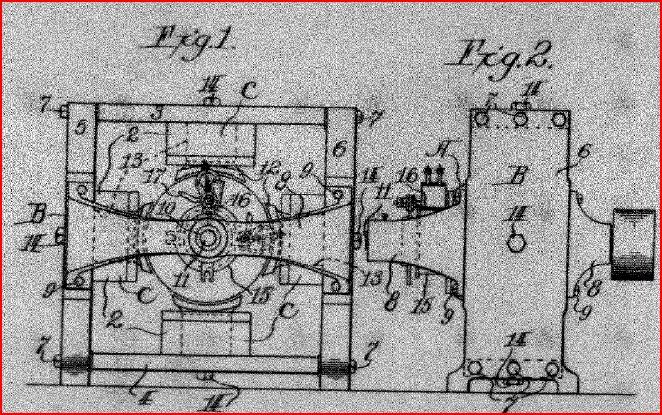
In the above drawings I have illustrated a motor having an armature A rotating within frame B in which it is journaled. The frame B carries electromagnetic poles C disposed about the armature to induce a magnetic field in which the armature rotates. The poles C are provided with electric windings 2 which are connected with the main circuits of the machine in the usual manner.
The frame B which I have illustrated is made up of top and bottom side parts 3 and 4 formed of soft wrought iron or other material having a high magnetic permeability. Side parts 5 and 6 are connected to the parts 3 and 4 by suitable bolts 7. The sides 5 and 6 are formed of hard cast iron or other suitable material having a low magnetic permeability. Bracket pieces 8 are formed with bearings 10 in which the shaft 11 of the armature is journaled.
The magnetic poles C are formed with tips 12 fastened to cores 13, the cores and pole tips being attached to the respective sides 3, 4, 5, and 6 on the frame B by means of suitable bolts 14. The pole tips 12 are composed of hard cast iron or other suitable material having a low magnetic permeability and are shaped to the periphery of the armature in the usual manner. The cores 13 are composed of soft wrought iron or other suitable material having a high magnetic permeability and are surrounded by the windings 2 adapted to induce electromagnetic action in the magnetic circuits of the machine. The armature A is of ordinary construction having a commutator 15 to which are fitted brushes 16 connected with terminals 17 of the machine. The material of the armature core is a soft iron of high magnetic permeability. It will be noted that the magnetic circuits induced in my motor during its operation by the application of electric current at the terminals 17 are made up of magnetic conductors having alternately high and low permeability. The magnetic lines, arising in the core 13 in the upper pole C which is connected with the side 3 of the frame B, pass through the pole tip 12 of hard iron, thence successively through the soft iron cor3e of the armature, the hard iron pole tip 12 connected with the side 5 or 6, the soft iron core 13 of the pole, the hard iron of the sides 5 and 6, the soft iron of the top side 3 and to the soft material of the core 13 where the lines originated. The other magnetic circuits in the machine are similarly made up and during the operation of the motor produce an action in the material of the circuits which prevents the heating and other obnoxious phenomena observed in motors of ordinary construction.
The number of alternations of material of high and low permeability in the magnetic circuits may be increased as desired, the structure described being merely illustrative. The form of the parts of the magnetic circuit may also be changed and may not necessarily constitute the motor frame, the essential feature of my construction being the alternately high and low permeability of the magnetic circuits of the machine.
The operation of my device does not differ from that of an ordinary electric machine except that it is unnecessary to have a starting box or rheostat in connection with motors to use in starting and reversing them.
The advantages of a structure producing the practical results described above is obvious and in a commercial machine the structure of which has been described I have secured all of these results permitting the stopping and starting of the machine under full load and its instant reversal without sparking at the commutator by reversing the direction of current at the terminals. No extra copper is used to produce these results over that in general practice.
Water may be thrown on the commutator while the machine is working under load without burning out the armature and the working of the machine under heavy overload does not overheat the coils and burn the insulation thereon, nor does it overheat any material in the magnetic circuit or circuits.
In practice I have found the proportions of one part or soft iron to one and four tenths parts of hard iron to produce very satisfactory results in the motor frame constructed in accordance with my invention...
US1262585
Electrical Motor
( 4-9-09 )
Electrical Motor
( 4-9-09 )
My invention relates to improvements in electric motors of the induction type whose rotor is entirely free from winding, insulated bars, or electrical fittings of any kind, the primary object being the production of a motor of maximum efficiency and simplicity and which is free from commutators, collector rings and unprotected insulated.
To these ends my invention comprises the features of construction and combination of parts hereinafter more particularly described and claimed.
In the accompanying drawings forming part of this specification,
Figure 1 is a longitudinal section of my invention, part of the structure being shown in full elevation;
Fig. 2 is a section taken on the line X-X,
Fig. 3 is a diagrammatic view showing the plan of wiring and operation of my invention, and
Fig. 4 and 5 are end views of details of the construction contained in Fig. 3.


In the drawings A indicates a stationary field magnet and B a rotor. The field magnet consists of a coil of soft iron wire or a circular piece or band of iron or other suitable material which acts as a core 2 with insulated wire 3 wound on said core for magnetizing the same. The field magnet consisting of said core and coil of insulated wire wound around said core is supported by a spider C, said spider consisting of a disk or plate 4 integral with a hub 5 and having a plurality of openings 6 evenly distributed about the axis of the spider and in which set bolts 7 are screwed outwardly through the peripheral portion of the disk. Positioned between the periphery of the disk and the inner surface of the insulated coil 3 on the core are a plurality of segmental buffers 8 made of fiber or other insulating or suitable material having inner recesses such as 9 in which the outer ends of the bolts 7 engage the segments or buffers and hold them pressed tightly against the coil 3, thus holding the field magnet in stationary position concentric with the axis of the spider.
D indicates a suitable base frame having two bearing standards 10 and 11 in the upper ends of which are seated journal boxes 12 in which a shaft E is freely journaled. The portion of the standard 10 containing one of the journal boxes is formed with an inwardly extending sleeve 13 arranged coaxially with said shaft and upon the inner end of which the hub 5 is fitted and secured rigidly by the set bolt 14. Thus the field magnet remains stationary with the shaft E disposed co-axially therewith and free to revolve.
The rotor B is the form of a circular plate or body 15 formed with a hub 16 secured to the shaft E by a set bolt 17 and with a circular endless sleeve 18 substantially incasing or encompassing the field magnet. Said sleeve is split and made in two parts 19 and 20 formed with flanges 21 on the outer portions bolted together and with a space or gap 22 on the inner portion admitting the disk 4 of the spider freely and without contact. Preferably the rotor is made out of aluminum whereby or other suitable non-magnetic material when desired. The shaft projects from one of the standards sufficiently to receive and support a drive pulley or coupling not illustrated, by which a drive pulley or coupling not illustrated, by which a driven element can be connected to transmit power. By means of the construction described the rotor is adapted to revolve entirely outside of the field magnet, to confine and take advantage of all the lines of force produced by the magnetic circuit. The field magnet of the magnet of the motor is wound in a coil and may be divided into six or any number of sections such as is illustrated in Fig. 2 when desired.
In the diagram one method of operating my improved motor is illustrated by the use of an armature of a synchronous rotary converter provided with a three wire circuit, but the method may be varied to suit various conditions as desired without departing from the spirit of my invention.
In operation ( see Fig. 3 ), for illustration, a motor having armature F is operated in the usual manner, being supplied with direct current from an ordinary line circuit. There are three lead wires 40, 41 and 42 connected to the commutator 23 at points equi-distant from each other around its periphery. Each lead therefore obtains an alternating current or impulse wave continuously changing its polarity. At any one position of the commutator, two of the leads are taking a current of one polarity, while the third lead is taking current of the opposite polarity, and this condition is changed three in each revolution of the commutator. The current resulting is three phase of long wave length.
In the field magnet B of the motor the current is fed for illustration through lead 43 into a section of coil 3 wound left handed creating a magnetic flux, in that part of the core and then crosses over and acts in a similar manner in an oppositely disposed section 26 of the winding, each terminal section of the field section being wound in a direction opposite to that of the leading section, 25 indicating one of the connections between a pair of the sections of winding. The terminal or lead 27 of section 26 connects with the collector ring 28 while to terminal or lead 43 connects with collector ring 31, thus completing the circuit back to the commutator. The coils as stated are duplicated and connected with the collector ring 29, and the action described thus takes place three times in the field windings during each revolution of the armature F. As a result there are three pairs of sections of field windings and three changes of polarity in the current produced in each revolution of the armature A, there are therefore nine distinct changes in the intensity and polarity of the impulse waves of current continually following each other in sequence in the field windings 3 of the motor.
The direction of motion of the rotor B is in accordance with the manner in which the coils in the field are connected. Reversing the connections causes the rotor to revolve in an opposite direction.
From the foregoing it would appear that an induced lagging current is set up in the rotor with a slight lag in phase within the aluminum or other electrically conductive rotor surrounding the winding upon a proper core, producing an appreciable torque.
The rotor in revolving is substantially noiseless due to the omission of brushes, collector rings and commutators and the winding is protected by the rotor so that there is no danger of the insulation becoming broken or damaged. The field magnet can also be easily adjusted by the set bolts 7, so that it centers accurately within the incasement of the rotor, Heating of the parts is also reduced to a minimum...