Tibor KEMENY
Cold Electricity
Cold Electricity
http://www.cosmic-construction.com/engelska_dokument/El-90-eng.Pdf
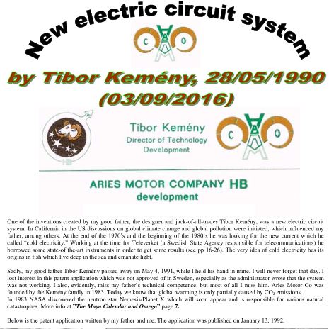
New
electric circuit system - Cosmic Construction
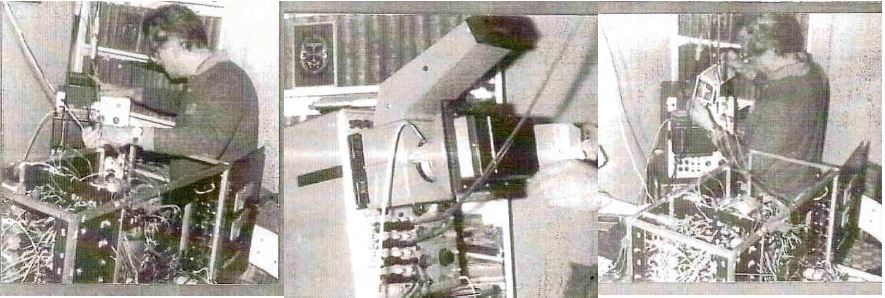
Sadly, my good father Tibor Kemény passed away on May 4, 1991, ... These appendices describe the new current, “Cold Electricity”
WO9118495
NEW ELECTRIC CIRCUIT SYSTEM
NEW ELECTRIC CIRCUIT SYSTEM
Inventor: KEMENY TIBOR [SE]
Applicant: ARIES MOTOR CO [SE]
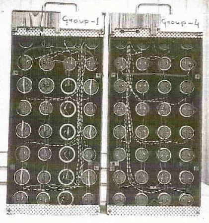
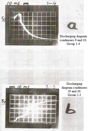
A new electric circuit system for electric cars, etc. is characterized as follows: a) a closed circuit system of two battery groups consisting of six batteries (1-3, 4-6) connected with each other in series, and likewise batteries (21-23, 24-26) also connected with each other in series; b) two condensers (9, 10) in the one battery group separate batteries (1-3 and 4-6) from one another, and two other condensers (29, 30) in the other battery group which separate batteries (21, 23) and (24-26) from each other; c) that when alternating discharges between the negative poles of condensers (9, 10) and (29, 30) occur, a hitherto unknown alternating current is brought about which is without resistance, tension an loss of heat and which is not governed by Ohm's law.;
This new alternating current is called "Cold Electricity". d) using this new electric circuit system the power of the electric car can be enhanced further if condensers (9, 10, 51, 52, 53, 54) are connected with each other in parallel. At the same time, however the number of thyristors is also increased.
The object of this invention is 2 new electric circuit system, which during the period of research was christened "Cold Electricity". Technicians in the electronics industry and the field of electricity have dreamed of a system which would enable electricity to move freely in a conductor without resistance and without any loss of the input energy at normal room temperature.
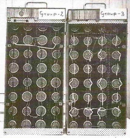
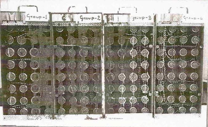
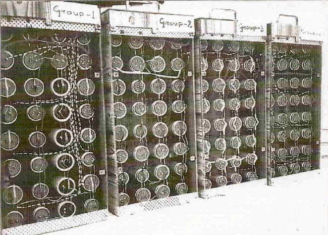
The NEW ELECTRIC CIRCUIT SYSTEM as proposed by the invention is based upon the use of two main groups consisting of six batteries in each group in which due to the unique construction there is a new type of electric current at normal room temperature.
The new electric circuit system, which has the characteristics indicated in the claims below, is not subject to Ohm's law. The new electric circuit will have applications which will have a world-wide market, such as street illumination,household and industrial applications and electric motors and electric cars.
In all of the aforesaid areas, energy and environmental conservation are the key factors for the future. Owing to the rigorous requirements in California and especially in Los Angeles such products as the electric car have an opportunity to solve the disastrous situation facing the entire planet as a result of a solution. This invention will be able solve the global environmental havoc caused by the exhaust fumes released by products coming from the car industry is new electric circuit system is well adapted to run electric motors and electric cars since the system works without resistance so tat the current flows freely in the motor circuit, an where is accordingly no loss of energy. All of this takes place at normal temperatures.
This new electric circuit system, in combination with a specially constructed electric motor, is more competitive than today's electric cars vis-à-vis conventional petrol-and diesel-powered cars.
The invention will be described referring to the following figures.
Fig.1 shows one of the battery groups consisting of six batteries.
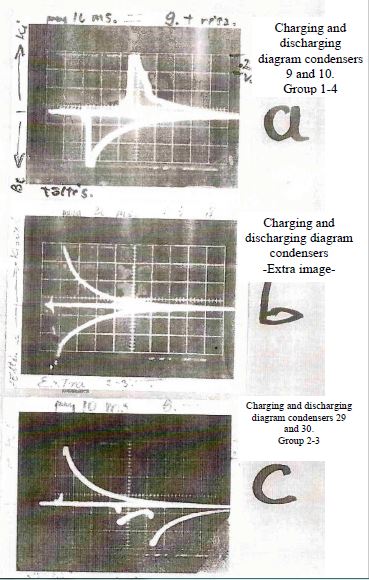
Batteries 1-3 are connected with each other in series as are batteries 4-6. Batteries 1-3 and 4-6 joined in series are separated by two specially constructed power condensers 9,10. The two manual switches 7,8 are, in fact, thyristors or switch transistors for high power, the function of which is effected by means of a control circuit (not included in the drawing) in which the frequency ranges from 0 upwards. 11 and 12 show transformers and appertaining bridge-connected rectifiers 13,14. At higher frequencies power transistors and transformers without iron cores should be used. 19 is an electromagnet positioned an an appertaining specially constructed electric motor. (The motor is not included in the drawing), The current flows alternatingly between the negative poles 9, 10 of the condensers through line 20. The inventor has named this current "Cold Electricity."
This current does not have tension but does,on the other hand, maintain its ampere strength. Since the current flows without resistance through the motor wiring, it can be called current without Watts, without loss of energy or heat and not subject to Ohm's law. This is a new electrical circuit system for, all electric motors and electric cars.
Fig.2 is a reversed diagram to Fig 1.
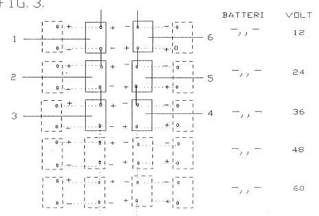
Fig.3 shows the possibilities, for example, of connecting in parallel or in series the one battery group 1-3 and the other 4-6 in Fig.1.
Fig.4 show is what manner motor power can be increased.
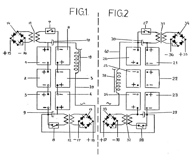
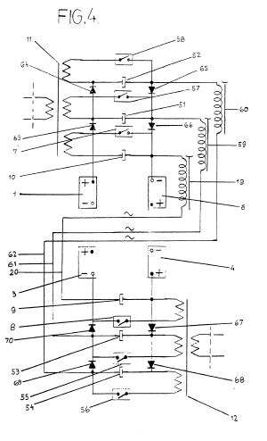
The condensers 9,10 in Fig.1 can accordingly be further connected in parallel with a number of condensers, e.g. 51, 52, 53 and 54, which are separated from each other by diodes 63, 64, 65, 66, 67, 68, 69 and 70. Each extra condenser 51, 52,53,54 has its own thyristor 55, 56, 57, 58, which in turn are connected to the positive poles of condensers 51, 52, 53, 54 together with a primary wire, which is connected to the transformers 11, 12. Each unit has a stator 59, 60 and wires 61, 62. The batteries 1-3 and 4-6 belong to Fig.1. Fig.2 can accordingly be reversed and used in the context of Fig.1 as indicated in Fig.4.
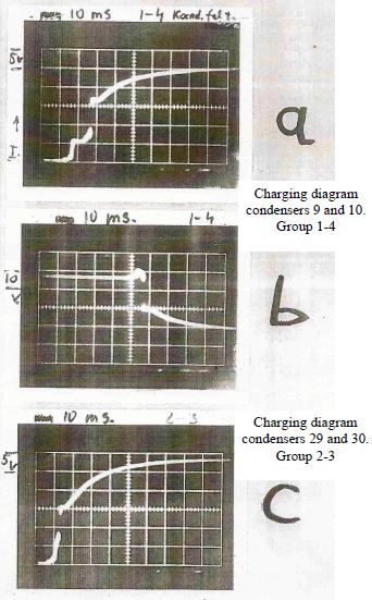
Fig.1 indicates that when thyristor 8 is switched on the condenser 10 is charged on battery 1, positive pole, and battery 5, negative pole, while thyristor 7 is switched off.
When thyristor 7 switches on, condenser 9 is charged on battery 4, positive pole, and battery 3,negative pole, while thyristor 8 switches off. Simultaneously condenser 10 is discharged through the primary wire 11 of the transformer, and, in the same moment there is a secondary induction, which is rectified by bridge 14, and in lines +15 and -16 the current is conducted on to batteries 24-26, Fig. 2. With the discharge of each condenser, a battery group is charged.
As a rule, the group which is not delivering current is always charged. When the thyristor 8 switches on, condenser 9 discharges via primary wire 12 of the transformer, and simultaneously is rectified on secondary induction current by bridge 13, and this induction current charges the batteries 21-23 Fig. 2.
Meanwhile condenser 10, by way of example, is recharged. When condenser 10 is charged, the other condenser 9 is discharged, and vice-versa.
Between the negative poles of the two condensers a new electric current is generated, the movement of which is affected by the electric vacuum of the condensers. In tis way a new type of alternating current is created.
The function of Fig.2 is the same as is described in Fig.1.
The secondary current indicated in Fig.2 also charges the batteries as indicated in Fig.1, and so forth.
The power of the electric motor can be further enhanced if several condensers are connected in parallel and, at the same, if the number of thyristors is also increased. When thyristor 7 switches on, condensers 9,53,54 are charged fro battery 4, positive pole, and battery 3 negative pole. When thyristor 8 switches on, condensers 10, 51, 52 are charged, simultaneously condenser 9 is discharged via the appertaining primary wire which is connected to transformer 12 in whose secondary ire.there is induction which charges the batteries as indicated in description in Fig.1.
In line 20 a new alternating current product is brought about which polarizes stator 19 to the north or south pole.
Stator 59 belonging to thyristor 57 is located in the motor and has a 120 degree staggering in relation to the original position of stator 19. The ignition of thyristor 57 also has a time staggering of 120 degrees in relation to the discharge of stator 19. Condenser 51 discharges in the same way as does condenser 10. The new alternating current is connected to the negative pole of condenser 53 via line 61 and stator 59, and at the same time, it polarizes stator 59 with corresponding poles. Stator 60, which belongs to thyristor 56, in turn, also has a 120 degree staggering in the motor in relation to stator 59; thyristor 56 also has a time staggering of 120 degrees.
The positive current of condenser 54 flows through the primary wire of transformer 12, which, in turn, induces current into its secondary wire as has been
previously described in Figure
The new alternating current is connected to the negative pole of condenser 52 via wire 62 and stator 60, and, at the same time, it polarizes the poles of
stator 60.
Thyristors 7,8/ 57,55/58,56 have a time staggering to each other of 120 degrees.
Fig.2 has an inverted drawing as indicated in Fig.4 in relation to Fig.1.