Yoshiaki KODAMA, et al
Microbubble Flotation
Microbubble Flotation
Microbubble
boundary layer reduces emissions, increases speed &
cargo capacity.
Related : Mitsubishi ALS
Related : Mitsubishi ALS
http://www.impactlab.net/2006/11/27/creating-slippery-ships-that-float-on-thin-air/
November 27th, 2006
Creating
Slippery Ships that Float on Thin Air
Yoshiaki Kodama is weaving a magic carpet large enough to carry a ship. Conjured up from thin air at the flick of a switch, this slippery blanket will help transport a fully laden tanker or container ship across the ocean at higher speed, and using far less fuel, than ever before.
Kodama is director of the Advanced Maritime Transport Technology Department at Japan’s National Maritime Research Institute (NMRI) in Tokyo. His work is just one of several major programmes under way in the US, Russia, Japan and Europe that focus on how to make ships more slippery.
A craft that has less friction as it slides through the water will be far more efficient than standard ships. Slippery ships could travel across the sea much faster or carry a bigger load on the same amount of fuel, saving money and reducing pollution. This is crucial, considering that in 2003 more than 90 per cent of all goods that were sent around the globe went by ship – that’s more than 6 billion tonnes, and the figure is set to increase.
A recent report from the Maritime Research Institute Netherlands (MARIN), based in Wageningen, says that reducing the friction and hence the drag on a ship’s hull could improve efficiency by up to 20 per cent. "There is currently no other technique in naval architecture that can promise such savings," it says.
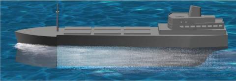
But how do you make a ship slippery? So far researchers have tried using tiny bubbles, slippery polymers and trapped sheets of air, and it seems that which method is best depends on what you want to achieve. If you simply wish to haul more cargo at a sedate 14 knots or so, in an environmentally responsible way using less fuel, then creating a carpet of microbubbles beneath a flat-bottomed hull may be the answer. On the other hand, the best option for a cargo ship expected to knife through the sea at more than 50 knots could be to cover the metal of the hull with a wall of air, effectively creating a boat in a bubble.
The idea of drag reduction began when British engineer William Froude investigated the fluid dynamics of ships in the 19th century. As a ship moves through water it encounters three types of drag: wave drag, pressure drag and frictional drag. Wave resistance is mainly a problem at high speed, and can be minimised with a carefully designed hull. Streamlining can also almost eliminate pressure drag – the backwards pull generated by the pressure difference between the bow and stern as the water through which a ship passes divides and then recombines. The greatest component of drag, and the main problem to ship designers, is frictional drag. This comes from the interaction between the hull and the water around it. Its effect, says Kodama, means that a ship pulls a large body of water along with it as it moves.
The region of water affected by the passage of a ship, known as the boundary layer, is usually measured in terms of the impact on flow past the hull. Typically, any water moving past the hull at less than 99 per cent of unobstructed flow is counted as part of the boundary layer. While the impact of a ship on the water around it decreases the further you move away from the hull, there are also variations between the bow and the stern. For a 300-metre-long ship, the boundary layer might be about half a metre thick at the bow, say, but tens of metres thick at the stern.
Frictional drag has the greatest impact on the centimetre or so closest to the ship, where interactions between the metal hull and the water are the strongest. One possible way to reduce this was first attempted in the early 1970s by Michael McCormick and Rameswar Bhattacharyya at the US Naval Academy at Annapolis, Maryland. They coated a cylinder with small bubbles of hydrogen generated by electrolysis, and dragged it through water. The result was a significant reduction in friction. Over the next decade, researchers showed that such microbubbles could decrease frictional drag by up to 80 per cent. However, the effect was difficult to replicate on real vessels.
Now researchers in Japan have decided to tackle this problem, and plan to turn the promise of microbubbles into reality as part of a programme to develop the "Super Eco-Ship". Led by Kodama, the project aims to reduce a ship’s greenhouse gas emissions by a quarter while increasing its cargo capacity by 20 per cent, through a whole series of propulsion, control and design changes. Japan has a particular interest here, given that most of its imports and exports travel by ship.
In theory, Kodama says, there is more than one mechanism by which microbubbles can help ships slip through water. First, the bubbles themselves form a sheet of air sandwiched between the water and the hull. Since the viscosity of air – its resistance to flow – is about 1 per cent that of water, the ship moves more easily.
Another mechanism modifies the turbulence that frictional drag creates in the water. The less turbulence generated, the easier the movement of a ship through the water. The researchers have found experimentally that the bubbles directly modify turbulence, Kodama says. "In turbulent flow, bubbles at the bottom of the boundary layer are under very strong shear forces, and become highly deformed and rather flat." This change in shape seems to reduce turbulence, so frictional drag drops.
Kodama’s team thought that one way to coat the hull with microbubbles would be to divert a little spare power from the engine to generate bubbles near the bow of the ship by blowing compressed air through a slot or porous plate. These bubbles would be swept backwards to almost completely coat the flat-bottomed hull. The buoyancy of the bubbles would tend to hold them in place under the ship, and those that were lost would continuously be replenished.
To test the effect, Kodama’s team and researchers at Tokyo and Osaka Universities dragged a large steel plate drilled with holes capable of releasing microbubbles along a 400-metre test tank. They even modified two ships to release bubbles from slots near the bow – a 6000-tonne cargo ship and a 10,000-tonne cement carrier. However, in sea trials Kodama saw a net drop in drag of only 3 per cent. With scale models, researchers at MARIN found reductions of less than 10 per cent.
These figures are nowhere near as great as theory and early tests might suggest. It seems there are all sorts of complications with applying microbubbles to real ships. For instance, there is a trade-off between the energy used to generate the bubbles and the energy saved by deploying them. Then you have to ensure that no bubbles reach the propeller. Propellers churning through air-filled water lack bite, and lose thrust. There are also many unknowns, such as where to locate the bubble ejectors, what bubble size and hull shape make best use of the effect, and crucially, how riding a carpet of air affects a ship’s maneuverability and seaworthiness.
Some problems are easily solved. Special deflectors or careful design of the rear of the hull, for instance, will ensure bubbles don’t reach the propellers. Others issues are still under investigation. When the cement carrier was rigged for tests early last year, for example, the slots emitting the bubbles were placed on either side of the bow. But the bubbles did not stay under the ship. And in other experiments the bubble carpet was effective for less than 50 metres downstream of injection. The vessel has been contracted for further experiments in 2007. This time, Kodama says, the team will inject air under the hull at two or three places along its length.
The good news is that there appears to be little problem with seaworthiness. In fact, according to the researchers in Japan and a series of experiments using models at MARIN, in most sea conditions, microbubbles either make ships more stable or have little effect.
But one problem seems intractable – microbubbles are only effective at relatively low speeds. "The higher the flow speed," says Kodama, "the greater the magnitude of turbulence. And that turbulence tends to drive the bubbles away from the hull." If they move further than a centimetre or so from the ship, all drag reduction is lost.
That’s a major problem for the US navy, which not only wants good fuel efficiency, but also high speed. In 2000, the US Defense Advanced Research Projects Agency (DARPA) began a programme to halve friction drag. Only this level of improvement, its researchers argued, could give meaningful increases in speed.
Instead of full-scale ship trials, DARPA is focusing on developing numerical models and computer simulations that will reveal how drag can be cut. Two teams are competing to produce the models, one at Stanford University in California and the other led by researchers from defence contractors General Dynamics. The results of these models are being validated by large-scale experiments at a huge US navy water-tunnel facility in Memphis, Tennessee, by a third team led by engineer Steve Ceccio at the University of Michigan at Ann Arbor. This tank is capable of testing sections of ships 3 metres across, in flows of more than 35 knots.
This programme aims to look at microbubbles, but also at the idea of coating hulls with slippery polymers by pumping them out through holes in the side of a vessel. Polymers are used to assist oil flow in the Trans-Alaska Pipeline System, for instance.
It is still early days, but trials at high flow rates using microbubbles revealed much the same difficulties that the Japanese teams encountered. For the first metre or so downstream from bubble injection "the
friction-drag reduction is unbelievable", says Marc Perlin, a researcher in Ceccio’s group. "You get to near-zero drag. But then shear forces throw the bubbles out of the boundary layer." This reduces the effect significantly. But, Perlin says, microbubbles could work well for slow-moving tankers. "Here the bubble effect would persist for a long distance."
At high speeds, polymers seem much more effective. The compounds the team has investigated include polyethylene oxide, which is used to make edible capsules for drugs, and polyacrylamide, which is employed as a flocculant in sewage treatment plants. The polymers probably won’t damage the environment, Perlin says, "but the navy isn’t keen on polymers because you have to carry them, and that reduces a ship’s payload."
Another form of lubrication is also generating interest. An air film of a few millimetres thick can be formed by pumping air across a super-water-repellent coating on the hull. The air becomes trapped next to the coating in preference to water, helping to reduce the friction between water and hull.
Yet Perlin and other researchers think that the best solution might come from a concept already explored by Russian engineers: air cavities. Although there has been little comment from DARPA, this idea is clearly under scrutiny at the agency, judging from the title of one of its latest research programmes: Air Cavity Drag Reduction (AirCat).
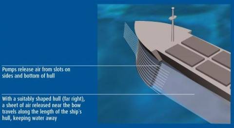
The plan is to look at ways to inject air into large cavities in the side and bottom of a specially designed hull (see Diagram). Air pockets sandwiched between the boat and the water should make a highly effective lubricant. Tests on models show it is possible to create stable cavities that cut drag by a factor of 5. Yet the project aims to reduce hull contact with water by a whopping 80 per cent, and to sustain these air cavities at all speeds and in all sea conditions. An AirCat-equipped ship could use sensors to monitor its air cavities, say, and optimise their shape using motors attached to movable panels.
The idea of air cavities has much in common with supercavitation, in which a submerged object such as a torpedo creates a single large bubble around itself. This slashes skin friction, bringing remarkable speeds within reach (New Scientist, 22 July 2000, p 26). Perhaps not surprisingly, Russian engineers who first developed supercavitating torpedoes have not only done plenty of research on air-cavity lubrication for ships, but have also put their ideas to work.
Since the 1980s, Russian shipyards have delivered at least 50 vessels, including patrol boats, ferries and landing craft, that are equipped with cavities in the hull. Pump air into them and they reduce drag by up to 40 per cent, yet require just 3 per cent of the vessel’s power to maintain. Most of these craft incorporate a stepped or notched hull to create a V-shaped cavity into which air is pumped. One of the advantages of this technology is that it can be retrofitted by fixing wedge-shaped segments across a hull to create steps. Engineers at the Krylov Shipbuilding Research Institute in St Petersburg say they can build low-speed ships that save up to 20 per cent in fuel, and high-speed ships that save even more. And you can already buy a high-speed motor yacht equipped with this technology.
But would it be money well spent? MARIN used models to compare air cavities, air films and microbubbles, and found that all resulted in net energy savings. "In our experiment," says Cornel Thill, a senior project manager at MARIN, "microbubbles were the least efficient, saving just a few per cent. The air film was better, and the air cavities performed the best." Thill thinks that this ranking could easily change as research progresses.
Whatever the details, drag reduction is an idea whose time has come, says Thill. He and his colleagues plan to build an air-lubricated motorised barge by 2009. And the Rotterdam-based DK Group, a company aiming to develop air cavity vessels, is working with Danish naval architects Knud E. Hansen to develop an air-cavity system for cruise liners, tankers and container ships. Eventually it aims to build a high-speed freighter that can cross the Atlantic in two-and-a-half days, about a quarter of the time taken by conventional ships. At that rate, who needs a magic carpet which flies in the air?
FRICTIONAL
RESISTANCE REDUCTION DEVICE FOR SHIP
US2011259440
US2011259440
A inject gas control device that performs, for example, control reflecting variation in vessel velocity over time without adversely affecting the main engine is realized. That is, it is prevented that gas is drawn too much and thereby a gas supply or charged air rate becomes insufficient, efficiency of the main engine is decreased and exhaust gas is deteriorated, and analogous events occur because the gas supply or charged air rate is too much instead. There are provided a main engine 4010 acquiring propelling power for a vessel 1, and a turbocharger 4011 that is driven by exhaust gas from the main engine 4010 and blows pressurized gas to the main engine 4010. A part of the pressurized gas and/or exhaust gas is drawn from between the turbocharger 4011 and the main engine 4010 (5023, 5024 and 5025).; The drawn pressurized gas and/or exhaust gas are injected in the proximity 9 of the hull on or below the waterline (5040), and the drawing rate of the pressurized gas and/or the exhaust gas is controlled on the basis of a physical quantity related to a heat load on the main engine 10 and characteristics of the turbocharger (4200).


METHOD
AND APPARATUS FOR REDUCING FRICTIONAL RESISTANCE OF SHIP
JP5311565
JP5311565
PROBLEM TO BE SOLVED: To keep the efficiency of a main engine by favorably supplying exhaust gas to a turbocharger, and to reduce the frictional resistance of a ship by controlling the jetting state of gas to be jetted in a vicinity of a hull by using bypass gas, and limiting diffusion of bubbles in a vicinity of a ship bottom while forming no operational trouble of the ship. ;SOLUTION: When reducing the frictional resistance of a ship 1 by jetting gas in a vicinity of a hull below the draft line of the ship 1, gas to be jetted in a vicinity of the hull from the periphery of a turbocharger for supplying pressurized gas to a main engine 10 is taken out, and the efficiency of a main engine 10 is kept in the predetermined range by controlling a variable means (a variable nozzle) for improving the air supply characteristic of the turbocharger according to at least the take-out status, and/or the gas jetting state is controlled by a baffle plate or the like when jetting the gas, and/or the comprehensive efficiency of the ship is improved by limiting the diffusion of the jetted gas by a variable limiting means (a diffusion limiting unit 95)
JET
GAS SUPPLYING METHOD AND JET GAS CONTROL DEVICE FOR MARINE
VESSEL
JP5403648
JP5403648
PROBLEM TO BE SOLVED: To materialize a jet gas control device performing control reflecting, for instance, a change in speed of a marine vessel with time without having adverse influence on a main engine, that is, to prevent the occurrence of reduction in the efficiency of the main engine, and deterioration of exhaust because of the shortage of an amount of air supply due to too much take-out of gas, or the occurrence of the similar things because of the excessiveness thereof. ;SOLUTION: The jet gas control device is provided with the main engine 10 providing the propulsion power of the marine vessel 1, and a supercharger 11 driven by the exhaust of this main engine 10, and supplying pressurized gas to the main engine 10. A part of the pressurized gas and/or exhaust is taken out of between this supercharger 11 and the main engine through an air supply bypass pipe 23, a scavenging bypass pipe 24, and an exhaust bypass pipe 25. This taken-out pressurized gas and/or exhaust is jetted out of a gas jetting port 40 in the vicinity of the body of the marine vessel at or below a draft line. Moreover, the amount of taking out of the pressurized gas and/or exhaust is controlled based on a physical quantity in association with the thermal load of the main engine 10 and the characteristics of the supercharger.
AIR-BUBBLE
HOLDING DEVICE FOR MARINE VESSEL
JP5311541
JP5311541
PROBLEM TO BE SOLVED: To provide an air-bubble holding device for a marine vessel, holding air bubbles under vessel navigation conditions and vessel conditions wherein, for example, an inclination of the marine vessel is caused at the time of turning or disturbance due to waves or a flow or the like, and preventing resistance to the advance of the marine vessel. SOLUTION: The air-bubble holding device for the marine vessel 1 is characteristically constituted of: gas exhaust nozzles 21, 22, 23, 24, 25 provided on a ship bottom 3 for exhausting the air bubbles; air supplying means 10, 11, 12, 13, 14 for supplying a gas to the gas exhaust nozzles 21, 22, 23, 24, 25; a drive unit for driving the air supplying means 10, 11, 12, 13, 14; and a plurality of end plates 5, 5' arranged almost on end portions of the ship bottom 3 at least backward relative to the gas exhaust nozzles 21, 22, 23, 24, 25 in a longitudinal direction of the ship bottom 3
BUBBLE
ENTRAINMENT PREVENTING DEVICE FOR SHIP
JP5311540
JP5311540
PROBLEM TO BE SOLVED: To provide a bubble entrainment preventing device in a ship, effectively reducing frictional resistance according to the navigation state and condition of the ship, preventing bubble entrainment with respect to a propeller means to prevent a decrease in efficiency of the propeller means, and improving a net frictional force reducing effect. SOLUTION: This bubble entrainment preventing device for the ship includes: the ship 1; air exhaust nozzles 21, 22, 23, 24, 25 ejecting bubbles to at least ship bottom 3 of the ship 1; blowers 10, 11, 12, 13, 14 delivering air to the air exhaust nozzles 21, 22, 23, 24, 25; the propeller 80 provided at the stern 9 of the hull 4 of the ship 1; and a substantially V-shaped mound 190 as an entrainment preventing structure for preventing bubble entrainment into the propeller 80, provided under at least the ship bottom 3 on the side of the stern behind the air exhaust nozzles 21, 22, 23, 24, 25.
FRICTIONAL
RESISTANCE REDUCTION DEVICE FOR SHIP
JP5604736
JP5604736
PROBLEM TO BE SOLVED: To provide a frictional resistance reduction device for a ship capable of properly changing the site of producing a bubble and the amount of bubbles according to a navigation state of a ship or the state of the ship, capable of effectively reducing frictional resistance by accurately blowing out the bubbles even when there is a disturbance, and capable of using an action of producing bubbles. SOLUTION: The frictional resistance reduction device for the ship comprises: a ship 1; a plurality of gas blowing openings 21, 22, 23, 24, 25 for blowing out the bubble at ship's bottom of the ship; a plurality of blowers 11, 12, 13, 14, 15 corresponding to the plurality of gas blowing openings for supplying the gas to the plurality of gas blowing openings; an electric motor for driving the plurality of air supply means; a navigation state detection part A110, a navigation state detection part B115 for detecting the navigation state of the ship; and a comparator 140 and a controller 150 for changing an air supply state by controlling the blower according to detection results of these navigation state detection parts.; The frictional resistance reduction device blows out the bubble by suppressing variation with respect to the disturbance such as a wave, and increases a reduction effect of the net frictional resistance by changing the number of gas blowing openings or the blowing amount of the bubble according to the navigation state.
BUBBLE
SUCTION PREVENTION TYPE INTAKE PORT DEVICE
JP5046102
JP5046102
PROBLEM TO BE SOLVED: To provide a bubble suction prevention type intake port device capable of preventing mixing of the bubbles to the inside of external water flowing-in to the intake port as much as possible by closing the bubbles included in the flow of water to the inside of a swirl flow generated along an opening surface and flowing it off to a downstream side when external water is taken-in through the intake port provided with the opening surface along a flowing direction of water on an outer plate part of a hull under a water level.; SOLUTION: In the intake port 1 provided with the opening surface along the flowing direction W of water under water, a large number of projection parts 3 as a trigonal pyramid are aligned on an outer peripheral front edge part of the intake port 1 in an upstream side of the flow of water so as to direct one of the distal end parts 3a to the upstream side of the flow of water. The bubbles included in the flow of water are closed in the swirl flow as an eddy generated on the respective projection parts 3, and the bubbles flow off to the downstream side without flowing-in into the intake port 1