Tim LUCAS
Resonant Macrosonic Synthesis ( RMS )
Resonant Macrosonic Synthesis ( RMS )
macrosonix.com
Popular Science, Vol. 252, No. 4 ( Apr 1998 ), Page 28
CNN.com : Invention may do for sound what laser did for light
9th Annual Discover Magazine Awards for Technological Innovation ( July, 1998 ) : MacroSonix's Resonant Sound Technology
Eureka Magazine ( August, 1998 ) : Bottled Sound is the Ultimate Power Source
Physics Today ( February 1998 ) : Ultrahigh-Energy Sound Waves Promise New Technologies
Scientific American ( February 1998 ) : Boom Box ~ A resonator boosts sound pressures to new highs
PATENTS
US5319938 -- Acoustic resonator having mode-alignment-canceled harmonics
US5515684 -- Resonant Macrosonic Synthesis
US5994854 -- Acoustic resonator power delivery
US6163077 -- RMS energy conversion
TW374827 -- RMS energy conversion
PATENT ABSTRACTS
WO9927636 -- Acoustic Resonator Power Delivery
MX9601981 -- Resonant Macrosonic Synthesis
EP0447134 -- Standing wave compressor.
US6388417 -- High stability dynamic force motor
US6230420 -- RMS process tool
US5357757 -- Compression-evaporation cooling system having standing wave compressor
http://www.macrosonix.com
Telephone 804-262-3700
FAX 804-266-4627
1570 East Parham Road Richmond , Virginia 23228
MacroSonix - Sound, Macro Waves and Reverberation

Our Technology
MacroSonix Corp. is a research and development company specializing in commercializing products based upon its core technologies, including its proprietary technology known as Resonant Macrosonic Synthesis, or RMS. RMS utilizes high-energy resonant sound waves inside closed cavities to perform mechanical functions such as compressing gases. The sound waves are typically actuated by a metal diaphragm driven by a linear motor, and use a microprocessor-based controller to maintain resonance. MacroSonix holds multiple patents on its core technologies.
Our Products and Services
MacroSonix is developing a number of compressor related products, including air and gas compressors, refrigeration condensing units and compressors, electronic cooling units, variable reluctance linear motors and acoustic resonators. In addition, we have recently begun working with outside organizations on early-stage feasibility studies for selected chemical processing applications for RMS, including atomization, powder processing, and chemical reaction acceleration.
MacroSonix also offers contract R & D services to other organizations which draw upon our core technical and prototyping competencies and capabilities.

Popular Science, Vol. 252, No. 4 ( Apr 1998 ), Page 28
CNN.com
December 2, 1997
Invention may do for sound what laser did for light
'It's doing something ... completely impossible'
by Jim Hill
'It's doing something ... completely impossible'
by Jim Hill
SAN DIEGO (CNN) -- A researcher says he has done something "completely impossible" by harnessing the power of sound, and that eventually it will be available in everything from home appliances to industrial compressors.
Tim Lucas says he made a radical discovery while working at the Los Alamos National Laboratory in New Mexico that enables him to create more energy through sound waves than was ever thought possible.
"It's not an incremental improvement in an existing technology," Lucas says, "it's suddenly doing something which before was completely impossible."
Scientists have long known that sound is composed of pulsing waves of energy, but it was considered useless as a power source because at high levels sound waves distort into shock waves.
An example is the way sound distorts on a stereo or radio speakers when turned up too loud.
But Lucas discovered that by sending sound waves through empty containers of various shapes, the shock waves were eliminated.
Clean electric power generators?
"Once you've done that," he says, "you can add all the energy, create all the pressure, and deliver all the power that you want."
Lucas calls his invention Resonant Macrosonic Synthesis -- RMS.
He has used it to power such things as a gas compressor, but believes there is so much potential that he compares what he has done with sound to what the laser has done with light.
His company, Macrosonix, is working on sound wave compressors which might one day do everything from cool refrigerators and air conditioners in the home to running compressors in factories and on construction sites.
The beauty of a sound-wave compressor is that it would do what a compressor does, but without the moving parts required in conventional piston technology.
Mechanical engineering professor Mark Hamilton, who has followed Lucas' work, says, "I don't think the idea struck people that you could use sound waves to do, say, pumping that could be used on a commercial scale. And I think that was the innovative part of the idea here."
Macrosonix researchers say they also hope to use sound to create clean electric power generators, replacing any number of machines with the technology of an empty cavity.
9th Annual Discover Magazine Awards for Technological Innovation ( July, 1998 )
MacroSonix's Resonant Sound Technology
INNOVATOR: TIM LUCAS
INNOVATOR: TIM LUCAS
Imagine a compressor in your refrigerator with no pistons, crankshafts, or lubricated bearings. Instead, all the work is done by sound waves bouncing around in an empty cavity.
When this idea first began bouncing around Tim Lucas's head ten years ago, his fellow physicists told him it would never work. Sound waves, they pointed out, can store only a relatively small amount of energy before turning into jagged shock waves that dissipate any added energy as heat. At least that's what happens when a wave travels through the open air, or through a cylindrical "wave guide." Undaunted, Lucas experimented and found that by shaping the sound chamber, or resonator, into something like a cone or a bulb, he could keep shock waves from forming. "Most of the research had been done in a simple cylindrical tube, and it turns out that's the one resonator guaranteed to give you a shock wave," says Lucas. "There's an infinite family of resonators that can give you non-shocked waves." In his technology, which he calls Resonant Macrosonic Synthesis, sound waves store thousands of times more energy than previously thought possible.
Lucas, who started his own company, MacroSonix Corp. in Richmond, Virginia, to develop RMS, has licensed it to one company (he won't say which) for refrigerator compressors--the part that compresses and circulates the coolant. The coolant passing through the cavity would be compressed when it encounters the high-pressure portion of the wave. Other applications might include cooling computer chips; "micronizaton," which is the pulverizing of particles down to microscopic size; and filtering out particles from factory exhaust (the sound waves would cause the particles to clump together). "We believe RMS is a new primary technology, something that functions at a fundamental level of physics," says Lucas.
Eureka Magazine ( August, 1998 )
Bottled Sound is the Ultimate Power Source
Sound waves could be a source of high energy in the future thanks to a technique that can better control their awesome power.
The breakthrough is known as Resonant Macrosonic Synthesis (RMS) and allows sound waves to be created - inside a closed resonator - with energy densities thousands of times greater than previously achieved.
The developer, MacroSonix, already has ideas on how to create new industry standards. These include clean electric power generation for the national grid, on-site power on demand or even hybrid electric vehicles. For these ideas RMS could be combined with pulse combustion science to convert fuels such as natural gas into electric power.
"RMS quite literally unlocks the power of sound," says Tim Lucas, founder and CEO of MacroSonix. "Now that large amounts of energy can be transferred into resonant sound waves, these waves can be used to perform industry's high-powered tasks in a completely new and simpler way.
It was always believed that there was an intrinsic limit for sound levels in gases that would prevent such high energy levels from existing - usually through the formation of shock waves. This barrier was broken in 1990, allowing RMS to be developed - with details now being released eight years later.
The key to RMS is the shape of the resonator. The resonator controls the shape of-the wave and can prevent the formation of shock waves. RMS allows the synthesis of non-shocked waveforms, which in turn allows large amounts of energy to be added to the wave, leading to extremely high dynamic pressures. Once an acoustic standing wave is formed the resonator’s geometry determines the resulting waveform, regardless of the wave’s amplitude.
Now that RMS can transfer this much energy into a sound wave, a wide range of physical effects becomes possible.
One example, says MacroSonix, is dynamic (oscillating) pressures in gases exceeding 500psi. Pressures call be generated well in excess of those needed commercial applications, with much higher pressures provided, if required.
The fluid power industry can also benefit through RMS’s, ability to compress gas or to pump liquids. This will remove the need for moving parts, lubrication oil and cut the risk of fluid contamination. Industries that may benefit from this include: chemicals – thanks to the ability to drive and control thermal and kinetic chemical reactions - pharmaceuticals, semiconductor manufacture, natural and commercial gas handling, refrigeration, air conditioning and air compression.
The technique might also be used for levitation for non-contact manufacturing process, by levitating and positioning heavy object within an RMS chamber.
One of the first areas to take advantage of the technology is a lubricant-free acoustic compressor which eliminates the need for CFCs and promises more energy efficiency. The compressor uses sound to compress the gas and has no moving parts - such as pistons, crank shafts and bearings - so needs no oil to lubricate them.
"The two waves which most apparently affect our everyday lives are electromagnetic waves and sound waves, ' says Lucas. "Electromagnetic waves have been commercialised for over 100 years but the commercial application of sound waves has only scratched the surface."
Physics Today ( February 1998 )
Ultrahigh-Energy Sound Waves Promise New
Technologies
by Ray Ladbury
by Ray Ladbury
Researchers in acoustics have long wondered whether sound waves could replace mechanical components in devices such as compressors, combustion engines, and pumps; now a team of researchers in Virginia has answered - with a very loud, YES!
Perhaps because we are constantly bombarded by sound, it is easy to forget that sound waves actually represent quite small pressure variations. The sound of a jet engine a few meters away measures only about 20 Pa (about 0.0002 atmospheres). As one increases the energy going into a sound wave, nonlinear processes in the gas in which the wave propagates direct more and more energy into harmonics of the drive frequency. The harmonics distort the sound wave and ultimately form shock waves. It is these shocks that limit the amplitudes attainable. Sound waves’ low energy levels and compression ratios (defined as the ratio of the waveform’s peak and minimum pressures) have limited their usefulness in high-power applications such as compressors and pumps. Accordingly, many researchers have wondered whether the acoustic saturation imposed by shock formation can be circumvented in some special circumstances.
Although acoustic saturation has been found to be inevitable (perhaps thankfully) for sound waves propagating in free space, the question of whether acoustic saturation is also unavoidable for standing waves in resonating cavities has received little attention. Recently, researchers at Macrosonix Corporation (Richmond, Virginia) have reported creating sound waves with energy densities 1600 times higher than was previously possible. According to Macrosonix founder and CEO Tim Lucas, pressures in these sound waves oscillate from peak values of up to10 atmospheres down to hard vacuum, rendering the concept of compression ratios all but meaningless.
Two papers presented by Macrosonix at the December 1997 meeting of the Acoustical Society of America in San Diego, California, discuss using resonator geometry to control the phases and amplitudes of harmonics in a waveform, thereby tailoring the waveform to a particular application. The researchers christened this technique Resonant Macrosonic Synthesis (RMS). As an application of RMS, they used a specifically designed resonator called a horn-cone (shaped like the bell of an elongated trumpet) to shape the waveform to avoid the discontinuity characteristic of a shock. The resulting shock-free sound waves can then be driven at much higher amplitudes.
Although the idea of using resonator geometry to control sound waveforms is not new, previous advances have been less dramatic. The newly synthesized sound waves are powerful enough to perform tasks that previously required mechanical components. Moreover, Lucas hopes to use RMS not only to attain high pressure amplitudes, but also to tailor the shapes and characteristics of waveforms to applications ranging from materials processing to pharmaceutical and chemical manufacturing to electric power generation.
Putting Sound to Work
Lucas originally became interested in generating large-amplitude acoustic waves when he realized that such waves could drive acoustic compressors that, in turn, could be used in environmentally benign refrigerators and pumps. After founding Macrosonix to tackle the technical problems involved in generating and controlling high-amplitude sound waves, Lucas spent a year at Los Alamos National Laboratory, where he worked in the lab of acoustical physicist Greg Swift. Lucas and his collaborators at Macrosonix then worked for the next seven years to develop methods of modeling non-linear phenomena associated with high-amplitude waves, find resonator geometries likely to achieve high amplitudes, create efficient mechanical drivers for their resonators and finally to harness a variety of high-energy acoustic effects to perform power hungry tasks such as gas compression, pulverization and electric power generation. By 1996, they had developed an acoustic compressor suitable for a commercially viable (and, yes, fairly quiet) acoustical refrigerator.
Developing viable acoustical technologies required a detailed understanding of the nonlinear phenomena associated with high-energy sound waves. Unfortunately most commercial software for acoustics implicitly assumes a small amplitude approximation. This forced the company to develop its own software for modeling the behavior of sound waves in cylindrically symmetric resonators. Beginning with conservation of mass and momentum (including viscous dissipation) and the state equation for an ideal gas, the team derived a set of coupled differential equations that could be solved numerically. As reported at the ASA conference, Lucas, Yurii Ilinksy, Bart Lipkens, Thomas Van Doren and Evgenia Zabolotskaya used the resulting model to predict the behavior of sound waves in a variety of resonators, including the horn-cone and others shaped like a cylinder, a cone and a bulb. The model was crucial for predicting which resonators were likely to avoid shocks at high pressure amplitudes.
Shock waves tend to form when the relative phases of the wave’s harmonics and fundamental frequency assume certain values. RMS uses resonator geometry to force the phases and amplitudes of harmonics to assume values other than those characteristic of shocks. For example, in consonant resonators, like a simple cylindrical cavity, the wave’s harmonics coincide with the higher modes of the cavity, providing precisely the conditions needed to generate shocks. In dissonant resonators (such as a cone), modes are not equally spaced, and so harmonics are less likely to coincide with cavity modes. As a result, resonators that achieve high pressure amplitudes are most likely to be dissonant, although even many dissonant resonators produce sever shocks at low pressure amplitudes. Hence the importance of being able to accurately model the physical processes occurring within the resonator.
The Macrosonix team also determined that efficient generation of high amplitude sound waves required a more effective method of driving the sound wave in the resonator. To effectively couple the mechanical motion of the driving force to the acoustic wave in the resonator, the team used a technique called entire-resonator drive, in which the resonator is shaken along its axis. In effect, this technique uses the entire inner surface of the resonator to drive the gas, rather than just a diaphragm of piston at one end, as was done in previous studies. As a result, entire resonator drive minimizes energy inefficiency. Even so, energy dissipation in the gas does raise its temperature and pressure, and therefore its sound speed and resonance frequency. Consequently, sensors in the cavity monitor the conditions in the gas and automatically adjust the drive frequency to remain on resonance.
According to Lucas, a major (so far unnamed) manufacturer of appliances has already licensed an RMS-based compressor design for use in a refrigerator, which is expected to be available commercially within two years. Lucas is confident that a range of other applications will mature in the near future. At present, however, researchers in acoustics are as interested in the characteristics of the high-amplitude acoustic waves as they are in their applications.
In the other paper presented by the company at the San Diego conference, Lucas, Van Doren, Lipkens, Christopher Lawrenson and David Perkins described measurements of waveforms and their dependence on driving-force amplitude and frequency (near resonance), as well as the effects of different gases on the waveform for a variety of resonator geometries, including cylindrical, conical, horn-cone and bulb. In general, regardless of the resonator, as the driving force (and therefore pressure amplitude) increased, the sound waves first changed from smooth to distorted sine waves, then developed ripples and finally discontinuous shock waves. However, resonator geometry was crucial in determining the pressure at which those transition occurred: Dissonant resonators achieved higher pressures than consonant resonators, and the horn-cone significantly outperformed the other dissonant resonators, as predicted by the Macrosonix model. The horn-cone was also more efficient at generating so-called DC pressure, a nonlinearly generated steady-state (nonoscillatory) pressure distribution that changes the local equilibrium pressure about which the sound waves oscillate. According to Lucas, such steady-state pressure differentials within the resonator up to 3.3 atmospheres and can be used in valveless pumps and compressors, as well as to levitate heavy objects.
The researchers also observed interesting hysteresis in which nonlinear processes in the gases caused an upward or downward shift in the resonance frequency as resonance was approached from below relative to that measured when resonance was approached from above. Moreover, whether the shift was null, upward or downward was determined by the resonator geometry, rather than by the properties of the gas. Indeed, aside from small differences in the pressures attained that depended on how nonideal the gas was, the waveforms looked the same for the three different gases investigated - R-134 (1,1,1,2-tetrafluroethane, a refrigerant), propane and nitrogen. This finding suggests that the same resonators may be used with different gases.
A Sound Future
Although Macrosonix nature as a startup high-tech firm has forced Lucas and his collaborators to maintain an applied, technical focus, Lucas is excited about the prospects for RMS in basic research as well as in technology. "RMS is a primarily technology," he stresses. "This is the first technique capable of generating sound waves of such amplitudes. I can’t wait to see what other researchers will do with these techniques." If the reception given to the papers presented in San Diego is any indication, Lucas’s fellow researchers are equally enthusiastic about potential applications of RMS in their own areas of research. As Steve Garrett of Pennsylvania State University put it, "If he ever puts these in commercial fridges, I’d buy one, throw away the fridge and just keep the pump to do science."
References
1. Y.A. Ilinskii, B. Lipkens, T.S. Lucas, T.W. Van Doren, E. A. Zabolotskaya, J. Acoust. Soc. Am., in press.
2. C.C. Lawrenson, B. Lipkens, T.S. Lucas, D.K. Perkins, T.W. Van Doren, J. Acoust. Soc. Am., in press.
3. D.F. Gaitan. A.A. Atchley, J. Acoust. Soc. Am. 93, 2489 (1993) and references therein.
4. See for example, A.B. Coppens, J.V. Sanders, J. Acoust. Soc. Am 58, 1133 (1975).
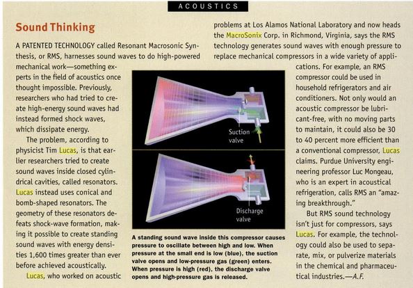
Acoustic compressors replace most of the mechanical parts in conventional compressors with standing sound waves. During one acoustic cycle, the pressure oscillates from high (red) to low (blue). In the first part of the cycle (upper image), low pressure in the narrow portion of the resonator closes the discharge (upper) valve and opens the intake (lower) valve. Allowing low-pressure gas into the resonator. In the second part of the cycle (lower image), high pressure in the narrow portion of the resonator closes the intake valve and allows high-pressure gas to flow through the discharge valve. Because they use no oil and have few moving parts, acoustic compressors are expected to be clean and reliable.
Scientific American ( February 1998 )
Boom Box ~ A resonator boosts sound pressures to new
highs
Blowing across the lip of a bottle to produce that satisfying hum would not seem the basis for new discoveries. But that is essentially what Timothy S. Lucas claims he has made. Reporting at the Acoustical Society of America meeting last December, the founder and president of Macrosonix Corporation in Richmond, Va., says his torpedo-shaped "bottles," when shaken back and forth hundreds of times a second, can create standing sound waves within them that pack energy densities 1,600 times greater than that previously achieved in acoustics. The process, which Lucas calls "Resonant Macrosonic Synthesis," can produce pressures exceeding 3.5 million pascals (500 pounds per square inch), more than enough for industrial applications such as compressing and pumping.
The key is the shape of the bottle, or resonator. In the past, resonators were often cylindrical, and shock waves formed inside them if they vibrated too quickly. A shock wave - a compression wave that delineates a sharp boundary between high and low pressures - dissipated energy, preventing the internal pressure from getting too high. As a result, driving the resonator faster - the equivalent of blowing harder across the top of a bottle - would no longer boost the volume the volume of the internal sound.
PATENTS
An acoustic resonator includes a chamber which contains a fluid. The chamber has a geometry which produces self-destructive interference of at least one harmonic in the fluid to avoid shock wave formation at finite acoustic pressure amplitudes. The chamber can have reflective terminations at each end or a reflective termination at only one end. A driver mechanically oscillates the chamber at a frequency of a selected resonant mode of the chamber. The driver may be a moving piston coupled to an open end of the chamber, an electromagnetic shaker or an electromagnetic driver.
BACKGROUND OF THE INVENTION
1) Field of Invention
This invention relates to an acoustic resonator in which near-linear macrosonic waves are generated in a resonant acoustic chamber, having specific applications to resonant acoustic compressors.
2) Description of Related Art
My earlier U.S. Pat. No. 5,020,977 is directed to a compressor for a compression-evaporation cooling system which employs acoustics for compression. The compressor is formed by a standing wave compressor including a chamber for holding a fluid refrigerant. A travelling wave is established in the fluid refrigerant in the chamber. This travelling wave is converted into a standing wave in the fluid refrigerant in the chamber so that the fluid refrigerant is compressed.
Heretofore, the field of linear acoustics was limited primarily to the domain of small acoustic pressure amplitudes. When acoustic pressure amplitudes become large, compared to the average fluid pressure, nonlinearities result. Under these conditions a pure sine wave will normally evolve into a shock wave.
Shock evolution is attributed to a spacial change in sound speed caused by the large variations in pressure, referred to as pressure steepening. During propagation the thermodynamic state of the pressure peak of a finite wave is quite different than its pressure minimum, resulting in different sound speeds along the extent of the wave. Consequently, the pressure peaks of the wave can overtake the pressure minimums and a shock wave evolves.
Shock formation can occur for waves propagating in free space, in wave guides, and in acoustic resonators. The following publications focus on shock formation within various types of acoustic resonators.
Temkin developed a method for calculating the pressure amplitude limit in piston-driven cylindrical resonators, due to shock formation (Samuel Temkin, "Propagating and standing sawtooth waves", J. Acoust. Soc. Am. 45, 224 (1969)). First he assumes the presence of left and right traveling shock waves in a resonator, and then finds the increase in entropy caused by the two shock waves. This entropy loss is substituted into an energy balance equation which is solved for limiting pressure amplitude as a function of driver displacement. Temkin's theory provided close agreement with experimentation for both traveling and standing waves of finite amplitude.
Cruikshank provided a comparison of theory and experiment for finite amplitude acoustic oscillations in piston-driven cylindrical resonators (D. B. Cruikshank, "Experimental investigation of finite-amplitude acoustic oscillations in a closed tube", J. Acoust. Soc. Am. 52, 1024 (1972)). Cruikshank demonstrated close agreement between experimental and theoretically generated shock waveforms.
Like much of the literature, the work of Temkin and Cruikshank both assume piston-driven cylindrical resonators of constant cross-sectional (CCS) area, with the termination of the tube being parallel to the piston face. CCS resonators will have harmonic modes which are coincident in frequency with the wave's harmonics, thus shock evolution is unrestricted. Although not stated in their papers, Temkin and Cruikshank's implicit assumption of a saw-tooth shock wave in their solutions is justified only for CCS resonators.
For resonators with non-harmonic modes, the simple assumption of a sawtooth shock wave will no longer apply. This was shown by Weiner who also developed a method for approximating the limiting pressure amplitude in resonators, due to shock formation (Stephen Weiner, "Standing sound waves of finite amplitude", J. Acoust. Soc. Am. 40, 240 (1966)). Weiner begins by assuming the presence of a shock wave and then calculates the work done on the fundamental by the harmonics. This work is substituted into an energy balance equation which is solved for limiting pressure amplitude as a function of driver displacement.
Weiner then goes on to show that attenuation of the even harmonics will result in a higher pressure amplitude limit for the fundamental. As an example of a resonator that causes even harmonic attenuation, he refers to a T shaped chamber called a "T burner" used for solid-propellent combustion research. The T burner acts as a thermally driven 1/2 wave length resonator with a vent at its center. Each even mode will have a pressure antinode at the vent, and thus experiences attenuation in the form of radiated energy through the vent. Weiner offers no suggestions, other than attenuation, for eliminating harmonics. Attenuation is the dissipation of energy, and thus is undesirable for energy efficiency.
Further examples of harmonic attenuation schemes can be found in the literature of gas-combustion heating. (see for example, Abbot A. Putnam, Combustion-Driven Oscillations in Industry (American Elsevier Publishing Co., 1971)). Other examples can be found in the general field of noise control where attenuation-type schemes are also employed, since energy losses are of no importance. One notably different approach is the work of Oberst, who sought to generate intense sound for calibrating microphones (Hermann Oberst, "A method for the production of extremely powerful standing sound waves in air", Akust. Z. 5, 27 (1940)). Oberst found that the harmonic content of a finite amplitude wave was reduced by a resonator which had non-harmonic resonant modes. His resonator was formed by connecting two tubes of different diameter, with the smaller tube being terminated and the larger tube remaining open. The open end of the resonator was driven by an air jet which was modulated by a rotating aperture disk.
With this arrangement, Oberst was able to produce resonant pressure amplitudes up to 0.10 bar for a driving pressure amplitude of 0.02 bar, giving a gain of 5 to the fundamental. The driving waveform, which had a 30% error (i.e. deviation from a sinusoid), was transformed to a waveform of only 5% error by the resonator. However, he predicted that if more acoustic power were applied, then nonlinear distortions would become clearly evident. In fact, harmonic content is visually noticeable in Oberst's waveforms corresponding to resonant pressure amplitudes of only 0.005 bar.
Oberst attributed the behavior of these finite amplitude waves, to the noncoincidence of the resonator modes and the wave harmonics. Yet, no explanations were offered as to the exact interaction between the resonator and the wave harmonics. Oberst's position seems to be that the reduced spectral density of the resonant wave is simply the result of comparatively little Q-amplification being imparted to the driving waveform harmonics. This explanation is only believable for the modest pressure amplitudes obtained by Oberst. Oberst provided no teachings or suggestions that his methods could produce linear pressure amplitudes above those which he achieved, and he offered no hope for further optimization. To the contrary, Oberst stated that nonlinearities would dominate at higher pressure amplitudes.
A further source of nonlinearity in acoustic resonators is the boundary layer turbulence which can occur at high acoustic velocities. Merkli and Thomann showed experimentally that at finite pressure amplitudes, there is a critical point at which the oscillating laminar flow will become turbulent (P. Merkli, H. Thomann, "Transition to turbulence in oscillating pipe flow", J. Fluid Mech., 68, 567 (1975)). Their studies were also carried out in CCS resonators.
Taken as a whole, the literature of finite resonant acoustics seems to predict that the inherent nonlinearites of fluids will ultimately dominate any resonant system, independent of the boundary conditions imposed by a resonator. The literature's prediction of these limits is far below the actual performance of the present invention.
Therefore, there is a need in the art to efficiently generate very large shock-free acoustic pressure amplitudes as a means of gas compression for vapor-compression heat transfer systems of the type disclosed in my U.S. Pat. No. 5,020,977. Further, many other applications within the field of acoustics, such as thermoacoustic heat engines, can also benefit from the generation of high amplitude sinusoidal waveforms.
SUMMARY OF THE INVENTION
It is an object of the present invention to provide acoustic resonators which eliminate shock formation by promoting the destructive self-interference of the harmonics of a wave, whereby near-linear acoustic pressures of extremely high amplitude can be achieved.
It is another object of the present invention to provide acoustic resonators which minimize the nonlinear energy dissipation caused by the boundary layer turbulence of finite acoustic waves.
It is a further object of the present invention to provide acoustic resonators which minimize boundary viscous energy dissipation and boundary thermal energy dissipation.
It is a still further object of the present invention to provide an acoustic driving arrangement for achieving high acoustic pressure amplitudes.
It is an even further object of the present invention to provide an acoustic resonator which can maintain near-sinusoidal pressure oscillations while being driven by harmonic-rich waveforms.
The acoustic resonator of the present invention includes a chamber containing a fluid. The chamber has a geometry which produces destructive self interference of at least one harmonic in the fluid to avoid shock wave formation at finite acoustic pressure amplitudes. The chamber has a cross-sectional area which changes along the chamber, and the changing cross-sectional area is positioned along the chamber to reduce an acoustic velocity of the fluid and/or to reduce boundary viscous energy dissipation. The chamber may comprise a resonant chamber for a standing wave compressor used for fluid compression for heat transfer operations.
The acoustic resonator driving system of the invention includes a chamber containing a fluid, wherein the chamber has acoustically reflective terminations at each end. A driver mechanically oscillates the chamber at a frequency of a selected resonant mode of the chamber. The acoustic resonator and drive system of the present invention may be connected to heat exchange apparatus so as to form a heat exchange system such as a vapor-compression system.
As described above, the acoustic resonator and acoustic driving arrangement of the present invention provide a number of advantages and achieve non-linear acoustic pressures of extremely high amplitude. In particular, the actual performance of the present invention is far beyond the results predicted in the literature of finite resonant acoustics.
These and other objects and advantages of the invention will become apparent from the accompanying specifications and drawings, wherein like reference numerals refer to like parts throughout.
BRIEF DESCRIPTION OF THE DRAWINGS
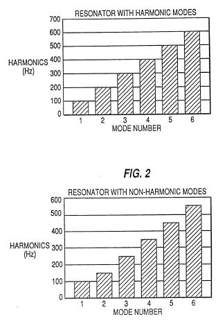
FIG. 1 is a graphical representation of a resonator having higher modes which are harmonics (i.e. integer multiples) of the fundamental;
FIG. 2 is a graphical representation of a resonator having higher modes which are not harmonics of the fundamental;
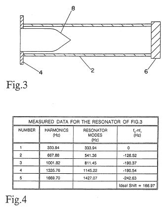
FIG. 3 is a sectional view of an embodiment of a resonator in accordance with the present invention, which employs an insert as a means of mode tuning;
FIG. 4 is a table of measured data for the resonator shown in FIG. 3;
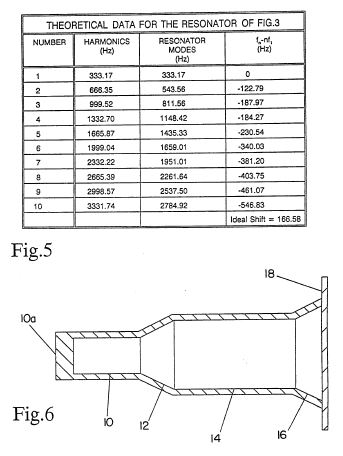
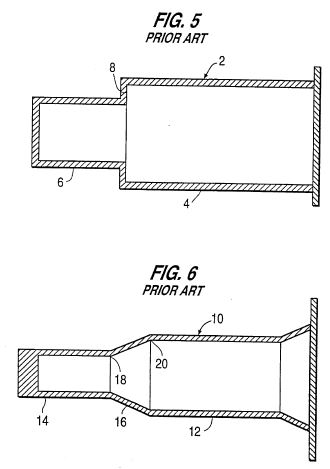
FIG. 5 is a table of theoretical data for the resonator shown in FIG. 3;
FIG. 6 is a sectional view of an embodiment of a resonator in accordance with the present invention which employs sections of different diameter as a means of mode tuning;
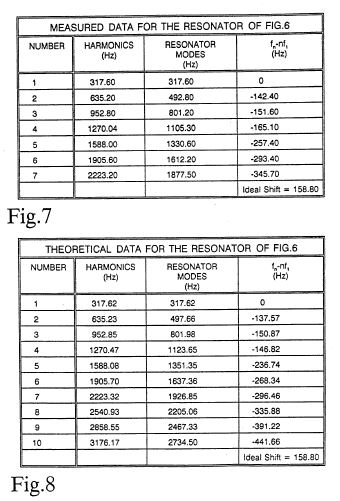
FIG. 7 is a table of measured data for the resonator shown in FIG. 6;
FIG. 8 is a table of theoretical data for the resonator shown in FIG. 6;
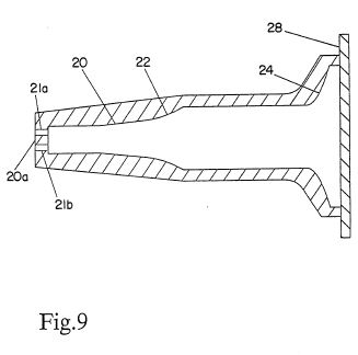
FIG. 9 is a sectional view of an embodiment of a resonator in accordance with the present invention showing further optimizations in resonator geometry;
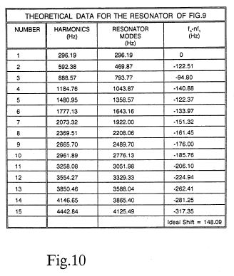
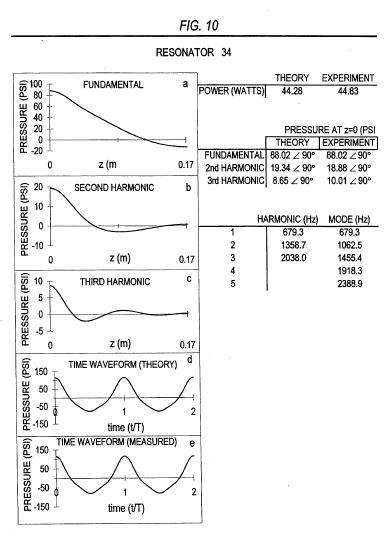
FIG. 10 is a table of theoretical data for the resonator shown in FIG. 9;
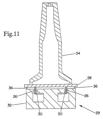
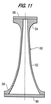
FIG. 11 is a sectional view of an apparatus used in a resonator driving system in accordance with the present invention, in which the entire resonator is oscillated along its longitudinal axis;
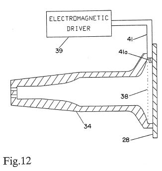
FIG. 12 is a sectional view of the resonator shown in FIG. 9 which employs porous materials for enhanced cancellation of higher harmonics; and
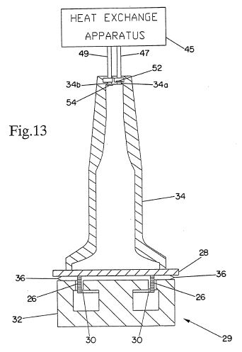
FIG. 13 is a sectional view of the resonator and driving system of FIG. 11 as connected to heat exchange apparatus to form a heat exchange system.
DETAILED DESCRIPTION OF THE PREFERRED EMBODIMENTS
Shock Elimination via Mode-Alignment-Canceled Harmonics
It is well known that "pressure steepening" at high acoustic pressure amplitudes leads to the classic sawtooth waveform of a shock wave. It is also understood that a sawtooth waveform implies, from Fourier analysis, the presence of harmonics.
If finite amplitude acoustic waves are generated in a constant cross-sectional (CCS) resonator, a shock wave will appear having the harmonic amplitudes predicted by the Fourier analysis of a sawtooth waveform. At first this would not seem surprising, but it must be understood that a CCS resonator has modes which are harmonic (i.e. integer multiples of the fundamental) and which are coincident in frequency with the harmonics of the fundamental. CCS resonators can be considered as a special case of a more general class of resonators whose modes are non-harmonic. Non-harmonic resonators hold a previously unharnessed potential for providing extremely high amplitude linear waves. This potential is realized by non-harmonic resonators which are designed to promote the self-destructive interference of the harmonics of the fundamental.
The present invention employs this principle and provides a new resonator design criterion; to optimize the self-cancellation of wave harmonics. This new design criterion for mode-alignment-canceled harmonics (MACH) eliminates shock formation. MACH resonators have achieved pressure amplitudes of 100 psi peak-to-peak, with mean pressures of 80 psia, without shock formation. This translates into a peak acoustic pressure amplitude which is 62% of the mean pressure.
Once the MACH design criterion is understood, many different resonator geometries can be employed for aligning a resonator's higher mode to promote self-cancellation of harmonics. A straightforward approach for exploiting the MACH principle is to align resonator modes to fall between their corresponding harmonics.
The bar graph of FIG. 1 illustrates the relationship between the harmonics of the fundamental and the resonator modes for a CCS 1/2 wave length resonator. The vertical axis marks the wave harmonics of the wave, and the bar height gives the resonant frequency of the mode. At a fundamental frequency of 100 Hz the wave will have harmonics at 200 Hz, 300 Hz, 400 Hz, etc. From FIG. 1 it can be seen that the harmonics of the wave are coincident in frequency with the modes of the resonator. Stated differently, the nth harmonic of the wave is coincident with the nth mode of the resonator. Consequently, little or no self-destructive interference of the wave harmonics will occur, and a shock wave can evolve without restriction. For a well developed shock wave, the pressure amplitude of the 2nd harmonic will be within 6 dB of the fundamental's amplitude.
The bar graph of FIG. 2 illustrates one of many possible arrangements for promoting the destructive self-interference of harmonics. In FIG. 2, the resonator modes are aligned to fall between the wave harmonics. For this example, the resonator modes have been shifted down in frequency so that the nth mode lies between harmonics n and n-1. With this arrangement a large degree of destructive self-interference of the wave harmonics can occur.
FIG. 3 is a sectional view of a resonator which was constructed and tested, and whose modes are shifted down in frequency. The resonator in FIG. 3 is formed by a hollow cylindrical chamber 2, an end flange 4, an end flange 6, and tapered rod insert 8, with all parts being aluminum. Tapered rod insert 8 was welded to end flange 4 with end flange 4 being welded to chamber 2. End flange 6 was welded to chamber 2, and was drilled to accommodate a process tube and a pressure transducer. Chamber 2 has an inside diameter of 5.71 cm, and an inside length of 27 cm. Tapered rod insert 8 has a half-angle end taper of 34.98 DEG, and a length of 10 cm, measured from end flange 4. Sharp edges on tapered rod insert 8 were rounded off to an arbitrary curvature to reduce turbulence.
Tapered rod insert 8 serves to create a smaller cross-sectional area along its length inside of chamber 2. In this way, the resonator of FIG. 3 is divided into two sections of different cross-sectional area, each section having its own acoustical impedance. This impedance change results in a shifting of the resonator modes to non-harmonic frequencies. The degree to which the modes are shifted can be controlled by varying the diameter and length of tapered rod insert 8. The manner in which the resonator is driven is described below.
FIG. 4 is a table of measured data obtained for the resonator of FIG. 3. The last column provides a relative measure of the degree of mode shift, by calculating the difference between the frequency "fn " of the nth mode and n times the fundamental frequency "nf1." The ideal mode shift, for placing the resonator modes at the midpoints between neighboring harmonics, is equal to 1/2 the fundamental frequency. For the FIG. 3 resonator, the ideal shift is f1 /2=166.97 Hz. For CCS resonators, the mode shift fn -nf1 =0 for each mode by definition.
The resonator design of FIG. 3 does not provide ideal mode shifts, but comes close enough to provide significant results. This is due to the fact that the Fourier sum of the first few harmonics contributes heavily to shock formation. Thus, significant cancellation of the 2nd, 3rd, and 4th harmonics will reduce shock formation greatly. When the resonator of FIG. 3 was pressurized to 80 psia with gaseous refrigerant HFC-134a, 11.8 Watts of acoustic input power was required to achieve a 42 psia peak-to-peak pressure amplitude (measured at end flange 4). This is within 30% of the required driving power predicted by a strictly linear theory which accounts for only thermal and viscous boundary layer losses. At these operating conditions the amplitude of the 2nd harmonic was 20 dB down from the fundamental, with higher harmonics being down 30 dB or more.
FIG. 5 is a table of theoretical data which was generated for the FIG. 3 resonator. Ideally, fn -nf1 should be approximately equal to the ideal shift for each of the resonator modes. However, it can be seen in FIG. 5 that the degree of mode shifting increases with mode number. At the 6th mode, shifting has increased so much that the mode frequency is now nearly coincident with the 5th harmonic of the wave. With more advanced resonator designs, many modes can be simultaneously tuned to lie between the wave harmonics. As the number of properly tuned modes increases, the resonator's linearity increases.
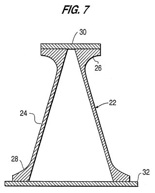
FIG. 6 is a sectional view of another resonator which was constructed and tested. The resonator in FIG. 6 has a chamber which is formed by a small diameter section 10, a conical section 12, a large diameter section 14, a conical taper 16, and an end flange 18. The chamber comprising the small diameter section 10, the conical section 12, the large diameter section 14, and the conical taper 16 were all machined from a single piece of aluminum. Aluminum end flange 18 was welded to conical end taper 16. Small diameter section 10 has a length of 7.28 cm and a diameter of 3.81 cm. Conical section 12 has a half-angle of 25.63 DEG and an inside length of 3.72 cm. Large diameter section 14 has an inside length of 13.16 cm and an inside diameter of 7.38 cm. Conical taper 16 has a half-angle of 26.08 DEG and an inside length of 2.84 cm. Section 10 and section 14 divide the resonator into two sections of different cross-sectional area, each section having its own acoustical impedance. This design results in a downward shifting of the resonator modes to non-harmonic frequencies.
The FIG. 6 resonator eliminates the tapered rod insert of FIG. 3, thereby reducing the internal surface area of the resonator, which in turn reduces the thermal and viscous boundary layer losses. The degree to which the modes are shifted can be controlled by varying the dimensions of section 10, section 14, conical section 12, and taper 16. Taper 16 compensates for excessive downward shifting of the higher modes, by shifting primarily the higher modes up in frequency. The manner in which the resonator is driven is described below.
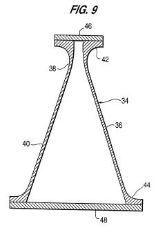
FIG. 7 and FIG. 8 are tables of the measured data and theoretical data, respectively, for the resonator of FIG. 6. In comparison with the FIG. 3 resonator, the FIG. 6 resonator has improved the tuning of the 2nd, 3rd, and 4th modes, as well as reduced the excessive shifting of higher modes. The FIG. 6 resonator brings the 2nd, 3rd, and 4th modes much closer to the ideal shift, and results in improved performance.
When the resonator of FIG. 6 was pressurized to 80 psia, with gaseous refrigerant HFC-134a, pressure amplitudes of up to 100 psi peak-to-peak (measured at an end 10a of small diameter section 10) were achieved without shock formation. However, turbulence was evident, indicating that the acoustic velocity was high enough to cause non-laminar flow. As shown below, resonator geometry can be altered to greatly reduce acoustic velocity. At 60 psi peak-to-peak (measured at the end 10a of small diameter section 10) all harmonics were more than 25 dB down from the amplitude of the fundamental, for the FIG. 6 resonator.
In general, the modes of a given resonator geometry can be calculated from the general solution of the wave equation written for both pressure and velocity:
P(x)=Acos (kx)+Bsin (kx)
V(x)=i/(pc)(Acos (kx)+Bsin (kx))
where i=(-1)@1/2, p=average fluid density, c=speed of sound. The arbitrary complex constants A and B are found by applying the boundary conditions of the resonator to the above equations for P(x) and V(x). Resonators embodying the present invention were designed by iterating P(x) and V(x) in the frequency domain across finite elements of the resonator, until zero velocity is reached at the resonator's end. As demonstrated above, the mid-harmonic placement of resonator modes provides one of many ways to exploit the MACH principle. For more exact predictions of harmonic cancellation, the harmonics can be treated as waves traveling within the boundaries of the resonator, while accounting for their self-interference. The goal of which is to show harmonic self-cancellation as a function of changes in the resonator geometry.
Importance of the MACH Principle
It is revealing to compare the performance of MACH resonators with that of CCS resonators which do not restrict shock formation. As a comparison, consider the normal evolution to shock formation which occurs as a finite amplitude wave propagates. Using the method of Pierce, it is possible to calculate the distance a 60 psi peak-to-peak pressure wave must travel for a fully developed shock wave to evolve (Allan D. Pierce, Acoustics, p. 571 (Acoustical Society of America 1989)). For a mean pressure of 80 psia (in gaseous HFC-134a), the waveform will evolve from a sinusoid to a shock after traveling only 22 cm, which is less than one traverse of the 27 cm length of the FIG. 6 resonator! From this it is easy to appreciate the longstanding assumption that at extremely high amplitudes, intrinsic nonlinearities of a gas will dominate any resonator design considerations.
Other Resonator Design Parameters
To efficiently create high amplitude resonant acoustic waves, it is important to keep the resonator boundary layer viscous and thermal losses as low as possible. Also, the acoustic velocity associated with a desired pressure amplitude should be minimized to avoid excessive turbulence.
For a pure sinusoidal standing wave in a resonator of constant cross-sectional area, the peak acoustic velocity is equal to P/(pc), where P.ident.peak acoustic pressure amplitude, p.ident.average fluid density, and c.ident.speed of sound at the average pressure. In practice, the peak acoustic velocity can be decreased by the proper resonator geometry. For example, the resonator of FIG. 6 has a peak acoustic velocity equal to 0.82(P/(pc)) (P being measured at the end 10a of small diameter section 10), due to the expansion at the center of the chamber provided by conical section 12. This increase in cross-sectional area occurs just before the velocity maxima at the center of the chamber, thereby lowering the acoustic velocity.
Expansions, like those of the FIG. 6 resonator, have other advantages as well. When the acoustic velocity is reduced, boundary layer viscous losses are reduced. Also, the expansion reduces the peak acoustic pressure amplitude at end flange 18, thereby reducing boundary layer thermal losses at this end of the resonator. Similarly, the expansion provided by end taper 16 of FIG. 6 further reduces the boundary layer thermal losses. When the position of an expansion, like conical section 12 of FIG. 6, is varied along the length of the resonator, the boundary layer thermal losses and the boundary layer viscous losses will vary. It has been found theoretically that the sum of these losses reaches a minimum when the expansion is centered at approximately 0.3 of the length of the resonator.
In general, practical energy efficient resonator designs require a compromise between mode tuning for harmonic cancellation, minimizing acoustic velocity, and minimizing thermal and viscous losses. FIG. 9 is a sectional view of a resonator which represents one of a vast number of possible compromises between these design parameters.
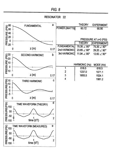
The FIG. 9 resonator chamber has a conical expansion section 20, a curved expansion section 22, a curved end taper section 24, and an end flange 28. Ports 21a, 21b, such as an inlet and outlet or valves, are provided at an end 20a of the resonator. Although not shown, such ports are also provided in the resonators of FIGS. 3 and 6. The resonator chamber is preferably formed by a low thermal conductivity material such as fiberglass, since this will reduce the boundary layer thermal losses. However, any material, such as aluminum, which can be formed into a desired configuration can be used. The FIG. 9 resonator is similar in principle to the FIG. 6 resonator in its method of modal tuning, except for the curved sections which provide greater mode tuning selectivity. This selectivity is due to the varying rate of change of cross-sectional area provided by the curved sections, which is explained as follows. The magnitude of frequency shift of a mode, caused by a given area change, depends on which part of the standing wave pattern encounters the area change. Each of the many superimposed standing wave patterns in a resonator will encounter a fixed area change at a different point along its wave pattern. Thus, an area change which tunes one mode properly may cause unfavorable tuning for another mode. Curved sections can provide compensation for this unfavorable tuning by exposing different modes to different rates of area change. The term "curved section" is not intended to refer to a specific mathematical surface. Rather, the term "curved section" is understood to mean in general any section which provides a rate of change of area, as a function of the longitudinal dimension, whose derivative is non-zero. Any number of mathematical surfaces can be employed. It is contemplated that one possible set of equations for the curved expansion section 22 and curved end tapered section 24 could be as follows.
In FIG. 9 the constant diameter section at end 20a of the resonator has an inner diameter of 2.54 cm and is 4.86 cm long. Conical expansion section 20 is 4.1 cm long and has a 5.8 DEG half-angle. Curved expansion section 22 is 3.68 cm long. To the right of curved section 22, the diameter remains constant at 5.77 cm over a distance of 11.34 cm. Curved end taper 24 is 2.16 cm long. To the right of curved end taper 24, the diameter remains constant at 13 cm over a distance of 0.86 cm. Curved expansion section 22 was described in a finite element program by the equation Dn =Dn-1 +0.00003(7+n), and curved end taper 24 was described by the equation Dn =Dn-1 +0.00038(n), where Dn .ident. the diameter of the current element, and Dn-1 .ident. the diameter of the previous element, and with each element having a length 0.00108 meters.
FIG. 10 is a table of theoretical data for the FIG. 9 resonator, which shows that the point at which modes and harmonics overlap in frequency has been significantly extended to higher frequencies.
The FIG. 9 resonator also reduces the acoustic velocity to a value of 0.58 (P/(pc)) (P being measured at a small diameter end 20a of the resonator), which represents a significant reduction in acoustic velocity for the desired pressure amplitude. In addition, the FIG. 9 resonator reduces the total thermal and viscous energy dissipation of the FIG. 6 resonator by a factor of 1.50. Neglecting turbulent losses, the total rate of thermal and viscous energy loss, at a given pressure amplitude, is equal to the acoustic input power required to sustain that pressure amplitude. Thus, reducing thermal and viscous energy losses will increase energy efficiency.
Half-Peak Entire-Resonator Driving
The odd modes of a resonator can be effectively driven by mechanically oscillating the entire resonator along its longitudinal axis. This is the preferred method used by the resonators of the present invention. Although the resonators of FIG. 3, FIG. 6, and FIG. 9 could be driven by coupling a moving piston to an open-ended resonator, this approach has certain disadvantages which are avoided by the entire resonator driving method.
Entire resonator driving can be understood as follows. If the entire resonator is oscillated along its longitudinal axis, then the end caps will act as pistons. The odd mode pressure oscillations at the two opposite ends of a double-terminated resonator will be 180 DEG out of phase with each other. Consequently, when the entire resonator is oscillated, its end caps, or terminations, can be used to drive an odd mode in the proper phase at each end of the resonator. In this way, the fundamental mode can be effectively driven.
FIG. 11 is a sectional view of one of many approaches which can be used to drive an entire resonator. In FIG. 11 an electrodynamic shaker or driver 29 is provided, having a current conducting coil 26 rigidly attached to end flange 28 of resonator 34, and occupying air gap 30 of magnet 32. Magnet 32 is attached to end flange 28 by a flexible bellows 36. Bellows 36 maintains proper alignment of coil 26 within air gap 30.
When coil 26 is energized by an oscillating current, the resulting electromagnetic forces will cause resonator 34 to be mechanically oscillated along its longitudinal axis. Magnet 32 can be rigidly restrained so as to have infinite mass relative to resonator 34. In the preferred embodiment, magnet 32 is left unrestrained and thus free to move in opposition to resonator 34. In either case, an appropriate spring constant can be chosen for bellows 36 to produce a mechanical resonance equal to the acoustic resonance, resulting in higher electro-acoustic efficiency. Bellows 36 could be replaced by other components such as flexible diaphragms, magnetic springs, or more conventional springs made of appropriate materials.
Entire resonator driving reduces the mechanical displacement required to achieve a given pressure amplitude. When driving the entire resonator, both ends of the resonator act as pistons. In most cases, entire resonator driving requires roughly half the peak mechanical displacement which would be needed for a single coupled-piston arrangement.
Half-Peak Entire-Resonator (HPER) driving provides the following advantages. As discussed above, the proper tuning of modes of a chamber is critical to efficiently achieving high acoustic pressure amplitudes. It follows that this tuning must remain constant during operation. Resonators which are terminated on both ends will maintain precise tuning during operation and throughout the lifetime of the resonator.
A further advantage relates to the use of HPER driving for acoustic compressors. Since HPER driven chambers are sealed, there are no oil-dependant moving parts that come in contact with the fluid being compressed; resulting in an inherently oil-free compressor. The suction and discharge valves needed for acoustic compressors would typically be placed at the narrow end of a resonator, where the pressure amplitudes are the greatest. For example, valve placement for the resonator of FIG. 9 would be positioned at ports 21a, 21b at end 20a. The ratio of pressure amplitudes at the two ends of the FIG. 9 resonator is approximately 3:1 (left to right).
Non-Sinusoidal Driving
As discussed above, a properly designed MACH chamber will cause the higher harmonics of its fundamental to be self canceling. For the same reason, a MACH chamber will tend to cancel out harmonics which may be present in the driver's displacement waveform. Thus, MACH chambers can convert a non-sinusoidal driving displacement into a sinusoidal pressure oscillation. In addition, any mechanical resonance present in a driver, like the driver of FIG. 11, would tend to convert a non-sinusoidal driving current into a sinusoidal displacement waveform.
In some applications, the use of non-sinusoidal driving signals can result in greater overall efficiency. For example, the power amplifiers needed for driving linear motors can be designed to operate very efficiently in a pulsed output mode. Current pulses can be timed to occur once every acoustic cycle or to skip several acoustic cycles.
Another type of non-sinusoidal driving, which MACH chambers can facilitate, is a fluid's direct absorption of electromagnetic energy, as disclosed in U.S. Pat. No. 5,020,977, the entire content of which is hereby incorporated by reference. Pulsed microwave and infrared energy, when passed through an absorptive fluid, will create acoustic waves in the fluid. This electromagnetic-to-acoustic conversion will tend to result in very harmonic-rich acoustic waves. MACH chambers will tend to cancel the resulting harmonics, thereby promoting a sinusoidal pressure oscillation. Electromagnetic pulses can be timed to occur once per acoustic cycle, or to skip several acoustic cycles.
Porous Materials
Porous materials, such as sintered metals, ceramics, and wire mesh screensare commonly used in the field of noise control. Porous materials can provide acoustic transmission and refection coefficients which vary as a function of frequency and acoustic velocity. Properly placed within a resonator, these materials can be used as an aid to mode tuning.
FIG. 12 is a sectional view of a resonator 34 illustrating one of many possible uses of porous materials. In FIG. 12 a porous material 38 is rigidly mounted near end flange 28 of resonator 34. Porous material 38 will have a minimal effect on the fundamental of the resonator, whose acoustic velocity becomes small near the surface of end flange 28. The higher modes of the resonator can have velocity maxima near the position of porous material 38. Thus, the higher harmonics of the wave can experience larger reflection coefficients at the porous material and be reflected so as to promote destructive self-interference. Tuning can be adjusted by varying the position of porous material 38 along the length of resonator 34.
In this way, a porous material can be used as an aid in optimizing the destructive self-interference of harmonics. The design flexibility provided by porous materials allows more aggressive optimization of specific resonator parameters, such as reducing the fundamental's acoustic velocity, without losing the desired mode tuning.
For microwave driven resonators, porous material 38 could also act together with end flange 28 to form a microwave cavity for the introduction of microwave energy into resonator 34. FIG. 12 illustrates an electromagnetic driver 39 coupled to the resonator 34 by a coaxial cable 41 having a loop termination 41a inside the resonator 34 in the area between the porous material 38 and end flange 28. The microwave energy would be restricted to the area between porous material 38 and end flange 28.
FIG. 13 is a sectional view of resonator 34 and drive apparatus 29 as used in a heat exchange system. In this case, ports 34a and 34b of resonator 34 are connected to a heat exchange apparatus 45 via conduits 47 and 49. Port 34a is provided with a discharge valve 52, and port 34b is provided with a suction valve 54. Discharge valve 52 and suction valve 54 will convert the oscillating pressure within resonator 34, into a net fluid flow through heat exchange apparatus 45. The heat exchange apparatus may include, for example, a conventional condenser and evaporator, so that the heat exchange system of FIG. 13 may form a vapor-compression system.
While the above description contains many specifications, these should not be construed as limitations on the scope of the invention, but rather as an exemplification of one preferred embodiment thereof. This preferred embodiment is based on my recognition that acoustic resonators can provide significant self-cancellation of harmonics, thereby providing extremely high amplitude acoustic waves without shock formation. The invention is also based on my recognition that other nonlinearities associated with finite amplitude waves, such as turbulence and boundary layer losses, can be reduced by proper resonator design.
Application of the MACH principle can provide nearly complete cancellation of wave harmonics. However, the present invention is not limited to resonators which provide complete cancellation. As shown in the above specifications, cancellation of a harmonic need not be complete to obtain shock-free high amplitude acoustic waves. Nor do all harmonics need to be canceled. There is a continuous range of partial harmonic cancellation which can be practiced. Harmonics can be present without shock formation, as long as their amplitudes are sufficiently small. Resonators which cancel one, two, or many harmonics could all be considered satisfactory, depending on the requirements of a particular application. Thus, the scope of the invention is not limited to any one specific resonator design.
There are many ways to exploit the basic features of the present invention which will readily occur to those skilled in the art. For example, shifting resonator modes to the midpoint between adjacent harmonics is only one of many ways to exploit the MACH principle. Resonator modes can be shifted to any degree as long as adequate self-destructive interference is provided for a given application.
In addition, many different resonator geometries can support standing waves and can be tuned to exploit the MACH principle. For example, a toroidal resonator can be tuned by using methods similar to the embodiments of the present invention. Although the present specification describes resonators whose modes are shifted down in frequency, similar resonator designs can shift modes up in frequency. For example, if the diameters of section 10 and section 14 in FIG. 6 are exchanged, then the resonator's modes will be shifted up in frequency rather than down. Furthermore, resonators can be designed to operate in resonant modes other than the fundamental, while still exploiting the MACH principle. Still further, the shock suppression provided by MACH resonators will occur for both liquids and gases.
Also, it is understood that the application of MACH resonators to acoustic compressors is not limited to vapor-compression heat transfer systems, but can be applied to any number of general applications where fluids must be compressed. For example, there are many industrial applications where oil-free compressors are required in order to prevent contamination of a fluid. Finally, many different drivers can be used with HPER driven resonators. For example, electromagnetic and piezoceramic drivers can also provide the forces required for entire resonator driving. In short, any driver that mechanically oscillates the entire resonator and provides the required forces can be used.
Accordingly, the scope of the invention should be determined not by the embodiments illustrated, but by the appended claims and their equivalents.
US5515684
Resonant Macrosonic Synthesis
Resonant Macrosonic Synthesis
Abstract -- An acoustic resonator includes a chamber containing a fluid. The chamber has anharmonic resonant modes and provides boundary conditions which predetermine the harmonic phases and amplitudes needed to synthesize a non-sinusoidal, unshocked waveform.
1) Field of Invention
This invention relates to acoustic resonators which are designed to provide the specific harmonic phases and amplitudes required to predetermine the waveform of extremely large acoustic pressure oscillations, having specific applications to acoustic compressors.
2) Description of Related Art
It is well known in the field of acoustics that when acoustic pressure amplitudes are finite compared to the medium's undisturbed ambient pressure, the resulting nonlinear effects will generate sound waves at harmonics of the fundamental frequency. We will hereafter refer to these nonlinearly generated sound waves as harmonics.
For both traveling and standing waves, the presence of high amplitude harmonics is associated with the formation of shock waves, which severely limit a wave's peak-to-peak pressure amplitude. Shock formation requires harmonic amplitudes that are significant relative to the amplitude of the sound wave at the fundamental frequency. We will hereafter refer to these as high relative amplitude harmonics.
For finite amplitude traveling waves, the harmonic relative amplitudes will depend primarily on the nonlinear properties of the medium. For finite amplitude standing waves occurring in a resonant cavity the harmonic relative amplitudes will likewise depend on the medium, but also are strongly influenced by the resonator's boundary conditions. The boundary conditions of the resonator are determined by the geometry of the walls and by the acoustical properties of the wall material and the fluid in the resonator.
As explained in U.S. Pat. No. 5,319,938, acoustic resonators can now be designed which provide very large and nearly sinusoidal pressure oscillations. FIG. 1 shows the waveform of a sinusoidal pressure wave. A sinusoidal wave is pressure symmetric implying that P+ = P- , where P+ and P- are the maximum positive and negative pressure amplitudes respectively. If a sinusoidal pressure oscillation is generated in a resonator having an ambient pressure P0, then (P0 + P+ ) cannot exceed 2P0, since otherwise the pressure symmetry would require that (P0 - P- ) be less than zero absolute, which is impossible. Thus, the maximum peak-to-peak pressure a sinusoidal oscillation can provide is 2P0. This ignores any changes in the ambient pressure caused by nonlinear processes driven by the acoustic pressures.
The '938 patent provides shock-free waves by preventing formation of high relative amplitude harmonics. However, there are acoustic resonator applications where the resulting sinusoidal waveforms present a limitation. For example, resonators used in acoustic compressors must at times provide compressions requiring P+ to be larger than P0 by a factor of 3 or more. An acoustic compressor used in low-temperature Rankine-cycle applications may require P+ to exceed 215 psia for a P0 of only 70 psia. The acoustic wave needed to fit these conditions would require an extreme pressure asymmetry (about the ambient pressure P0) between P- and P+.
Previously, the generation of resonant pressure-asymmetric waves presented specific unsolved problems. For a waveform to deviate significantly from a sinusoid, it must contain high relative amplitude harmonics. These harmonics would normally be expected to lead to shock formation, which can critically limit peak-to-peak pressure amplitudes as well as cause excessive energy dissipation.
Resonant acoustic waves have been studied theoretically and experimentally. With respect to the present invention, these studies can be grouped into two categories: (i) harmonic resonators driven off-resonance, and (ii) anharmonic resonators driven on-resonance.
A resonator is defined as "harmonic" when it has a set of standing wave mode frequencies that are integer multiples of another resonance frequency. For the following discussions only longitudinal resonant modes are considered. Harmonically tuned resonators produce shock waves if finite amplitude acoustic waves are excited at a resonance frequency. For this reason harmonic resonator studies which examine non-sinusoidal, non-shocked waveforms focus primarily on waveforms produced at frequencies off-resonance. Driving a resonator off-resonance severely limits the peak-to-peak pressure amplitudes attainable.
The following references are representative of the harmonic resonator studies: (W. Chester, "Resonant oscillations in closed tubes," J. Fluid Mech. 18, 44-64 (1964)), (A. P. Coppens and J. V. Sanders, "Finite-amplitude standing waves in rigid-walled tubes," J. Acoust. Soc. Am. 43, 516-529 (1968)), (D. B. Cruikshank, Jr., "Experimental investigations of finite-amplitude acoustic oscillations in a closed tube," J. Acoust Soc. Am. 43, 1024-1036 (1972)) and (P. Merkli, H. Thoman, "Thermoacoustic effects in a resonance tube," J. Fluid Mech. 70, 1161-177 (1975))
A resonator is defined as "anharmonic" when its does not have a set of standing wave mode frequencies that are integer multiples of another resonance frequency. Studies of anharmonic resonators driven on-resonance are usually motivated by applications in which the elimination of high relative amplitude harmonics is necessary. For example, thermoacoustic engine resonators require high amplitude sine waves, and thus are designed for the greatest possible reduction of harmonic amplitudes. An example of such a study can be found in the work of D. Felipe Gaitan and Anthony A. Atchley (D. F. Gaitan and A. A. Atchley, "Finite amplitude standing waves in harmonic and anharmonic tubes," J. Acoust. Soc. Am. 93,2489-2495 (1993)).
Gaitan and Atchley provide anharmonic resonators by using geometries with sections of different diameter. The area changes occurred over a distance that was small compared to the length of the resonator. As explained in U.S. Pat. No. 5,319,938 this approach tends to provide significant suppression of the wave's harmonics, thus providing sinusoidal waveforms.
In summary, those resonators driven on-resonance at finite amplitudes either produced sinusoidal waves or shock waves. Resonators driven off-resonance resulted in very low peak-to-peak pressure amplitudes.
The ability to provide high peak-to-peak pressure amplitude, non-sinusoidal, unshocked waves of a desired waveform would represent a significant advance for high compression acoustic resonators. Such waveforms require high relative amplitude harmonics to exist when the resonator is excited at a resonant frequency.
Consequently, there exists a need for resonators that can synthesize unshocked waveforms at high pressure amplitudes.
SUMMARY OF THE INVENTION
It is an object of the present invention to provide acoustic resonators whose boundary conditions maintain the predetermined harmonic phases and amplitudes needed to synthesize a desired waveform.
A further object of the present invention is to provide acoustic resonators whose boundary conditions are designed to exploit the relative phases of harmonics as a means to dramatically extend the pressure amplitude shock-limit normally associated with high relative amplitude harmonics.
A still further object of the present invention is to provide extremely high-amplitude pressure-asymmetric waves at resonance.
The acoustic resonator of the present invention includes a chamber containing a fluid. A chamber's geometry, as well as the acoustic properties of the chamber wall material and the fluid, creates the boundary conditions needed to produce the harmonic phases and amplitudes of a predetermined waveform. The chambers have a continuously varying cross-sectional area in order to avoid turbulence due to high acoustic particle velocities, and in order to allow high relative amplitude harmonics.
The acoustic resonators of the invention can be used in acoustic compressors to provide large compressions for various applications, such as heat exchange systems.
As described above, the acoustic resonators of the present invention provide a number of advantages and can achieve peak-to-peak acoustic pressure amplitudes which are many times higher than the medium's ambient pressure. In particular, it is a surprising advantage that these extremely high amplitude pressure oscillations, which have precisely controlled waveforms, can be provided with very simple resonator geometries.
These and other objects and advantages of the invention will become apparent from the accompanying specifications and drawings, wherein like reference numerals refer to like parts throughout.
BRIEF DESCRIPTION OF THE DRAWINGS
FIG. 1 is a graphical representation of the absolute peak-to-peak pressure amplitude limit for a sine wave;
FIG. 2 is a graphical representation of the mode frequencies and harmonic frequencies for a harmonically tuned resonator;
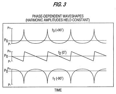
FIG. 3 is a graphical representation of the waveforms produced within a harmonically tuned resonator, when the drive frequency is varied about the fundamental resonance;
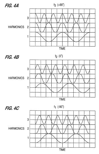
FIGS. 4A-4C is a graphical representation of the relative harmonic phases corresponding to the three waveforms shown in FIG. 3;
FIG. 5 is a sectional view of a resonator which provides a stepped impedance change;
FIG. 6 is a sectional view of a resonator which provides a partially distributed impedance change;
FIG. 7 is a sectional view of a resonator in accordance with the present invention which employs a distributed impedance change geometry for producing asymmetric positive waveforms;
FIG. 8 provides theoretical and experimental data for the resonator shown in FIG. 7;
FIG. 9 is a sectional view of a resonator in accordance with the present invention which employs a distributed impedance change geometry for altering the harmonic amplitudes of the resonator in FIG. 7;
FIG. 10 provides theoretical and experimental data for the resonator shown in FIG. 9;
FIG. 11 is a sectional view of a resonator in accordance with the present invention which employs a distributed impedance change geometry for producing asymmetric negative waveforms;
FIG. 12 provides theoretical data for the resonator shown in FIG. 11;
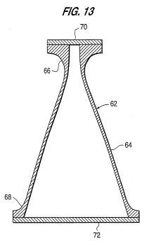
FIG. 13 is a sectional view of a resonator in accordance with the present invention which employs a distributed impedance change geometry for producing asymmetric negative waveforms;
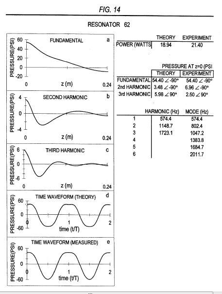
FIG. 14 provides theoretical and experimental data for the resonator shown in FIG. 13;
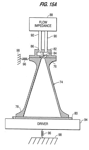
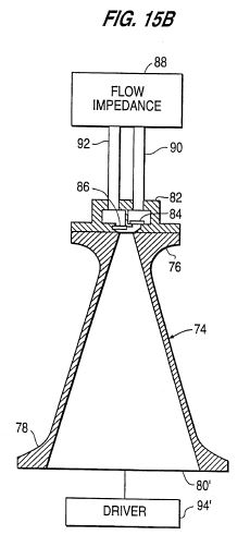
FIGS. 15A and 15B are sectional views of a resonator in accordance with the present invention which is employed in an acoustic compressor; and
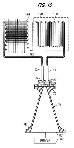
FIG. 16 is a sectional view of a resonator in accordance with the invention shown within a compressor/evaporation system.


DETAILED DESCRIPTION OF THE PREFERRED EMBODIMENTS
Anharmonic resonators having localized impedance changes
As described in U.S. Pat. No. 5,319,938, anharmonic resonators with abrupt changes in cross sectional area will significantly reduce the relative amplitudes of the harmonics. These abrupt changes in area introduce a localized acoustic impedance change within the resonator. An example of an abrupt impedance change is shown in FIG. 5, where a resonator 2 is formed by joining a large diameter section 4 to a small diameter section 6. This abrupt change in cross sectional area creates an impedance step 8, which is highly localized with respect to the resonator's length.
Since localized impedance change (LI hereafter means Localized Impedance change) resonators tend to maintain harmonics at low relative amplitude, the waveform remains substantially sinusoidal.
Anharmonic resonators having distributed impedance changes
The preferred embodiment of the present invention includes a resonator having a distributed impedance change (DI hereafter means Distributed Impedance change). Unlike LI resonators, DI resonators can easily allow high relative amplitude harmonics to exist.
The resonators shown in FIGS. 5, 6, 7, 9, 11 and 13 illustrate the differences between LI and DI resonators. FIG. 6 shows a resonator 10 which is reproduced from FIG. 6 of U.S. Pat. No. 5,319,938. Resonator 10 includes conical section 16 which joins large diameter section 12 to small diameter section 14. Unlike the resonator of FIG. 5, this change in cross sectional area is not completely localized, but is partially distributed. This partially distributed area change results in a partially distributed impedance change, which occurs along the length of conical section 16.
Here, and throughout, the term partially distributed is used to imply less than the entire length of the resonator. The terms LI and DI are not used to imply a specific extent of distribution. For example, between the LI resonator of FIG. 5 and the fully DI resonators of FIGS. 7, 9, 11 and 13 there exists a continuum of partially DI resonators. Thus, the present invention's scope is not limited to a specific degree of distributed impedance. Conversely, the scope of the invention includes the employment of the specific distributed impedance required by a given application or desired waveform.
The resonators shown in FIGS. 7, 9, 11 and 13 provide embodiments of the present invention which avoid abrupt area changes in order to provide high amplitude harmonics. When compared at the same fundamental amplitude, the present invention's resonators can provide higher amplitude harmonics than the more abrupt area change resonators shown in FIGS. 5 and 6.
Due to their comparatively low relative amplitude harmonics, the resonators of FIGS. 5 and 6 would need much higher fundamental amplitudes to generate the relative harmonic amplitudes needed to cause an appreciable change in the waveform. However, the excessive turbulence caused by abrupt area changes makes higher fundamental amplitudes extremely difficult and inefficient to achieve.
For example, when the resonator of FIG. 6 has an average pressure P0 of 85 psia and a peak-to-peak pressure amplitude of 60 psi, all harmonic amplitudes are at least 25 dB below the fundamental, resulting in a nearly sinusoidal waveform. At peak-to-peak pressures of 60 psi and above, turbulence begins to dominate the performance, as evidenced by high-amplitude high-frequency noise riding on the fundamental, and by excessive power consumption.
In order to avoid turbulence at the design conditions the preferred embodiment of the present invention includes resonators having a radius r and an axial coordinate z, where dr/dz is continuous wherever particle velocities are high enough so as to otherwise cause turbulence due to the discontinuity. The preferred embodiment also avoids excessive values of d@2 r/dz@2 where particle velocities are high, in order to prevent turbulence which would otherwise occur as a result of excessive radial fluid accelerations.
Harmonic phase within harmonic resonators
In order to provide some helpful insight into the resonators of the present invention it is instructive to first examine the simpler case of harmonic resonators.
Within harmonic resonators, harmonic phases have a strong but predictable frequency dependence when the drive frequency is in the vicinity of a mode frequency, as shown in the literature (see for example, W. Chester, Resonant oscillations in closed tubes, J. Fluid Mech. 18, 44-64 (1964)).
These effects are considered for harmonics 1-5 as follows for the example of a harmonic resonator driven at frequencies very close to a mode frequency. FIG. 2 illustrates the case of a perfectly harmonic cylindrical resonator for three drive frequencies: f1 below, f2 equal to and f3 above the resonance frequency of mode 1. The bottom horizontal axis indicates the resonance frequencies of the first five modes of the resonator (denoted by the vertical lines at 100, 200, 300, 400 and 500 Hz). The three horizontal lines with superposed symbols provide axes for the wave's fundamental and associated lower harmonics (denoted by the symbols) at drive frequencies f1, f2 and f3.
The frequency-dependent harmonic phase relationships can be qualitatively demonstrated by the following:
where E(t) is the acoustic pressure(which adds to the ambient pressure P0), An is the amplitude of each harmonic n, f is the ##EQU1## fundamental (or drive) frequency of the acoustic wave and .phi.n is the frequency-dependent phase of each harmonic n.
FIG. 3 provides the resulting waveforms, as measured at either end of the cylindrical resonator, for the three drive frequencies f1, f2 and f3 of FIG. 2. All of the drive frequencies f are near the lowest resonance frequency of the resonator. For this example, the amplitudes of the fundamental and harmonics are given by An =1/n for each of the three waveforms (note that this ignores any frequency dependence that An may have). In FIG. 3, time is the horizontal axis and pressure is the vertical axis, where P0 is the ambient pressure of the medium.
Referring to FIG. 2, drive frequency f1 is below the mode 1 frequency, causing the frequency of harmonic n (nf1) to fall between the frequencies of modes n-1 and n. The resulting fundamental and harmonic phases are .phi.n =-90 DEG for each n. The pressure waveform is calculated using Equation 1 and is denoted by f1 in FIG. 3. This waveform is referred to as asymmetric negative (AN), since P- > P+ .
Drive frequency f2 in FIG. 2 is equal to the mode 1 frequency, causing the frequency of harmonic n to be equal to the frequency of mode n. The resulting fundamental and harmonic phases are .phi.n =0 DEG for each n. The pressure waveform is denoted by f2 in FIG. 3, where the wave is shocked and P+ = P- .
Drive frequency f3 in FIG. 2 is greater than the mode 1 frequency but less than the mode 2 frequency, causing the frequency of harmonic n to fall between the frequencies of modes n and n+1. The resulting fundamental and harmonic phases are .phi.n =90 DEG for each n. The pressure waveform is denoted by f3 in FIG. 3, and is referred to as asymmetric positive (AP), since P+ > P- .
The relative phases of the first three harmonics (with frequencies f, 2f and 3f) for each waveform shown in FIG. 3 are demonstrated in FIGS. 4A-4C. Note that the amplitude of each harmonic has been normalized. For different phase angles .phi.n the relative positions in time of each harmonic component of a wave change.
When the harmonic resonator's drive frequency is swept up through the lowest resonance frequency the phases .phi.n sweep from -90 DEG through 0 DEG (at resonance) to +90 DEG taking a continuum of values within the range. Note that as the drive frequency f is swept through the resonance frequency of mode n=1, each harmonic frequency nf will be swept through the resonance frequency of the nth mode. Phases .phi.n between -90 DEG and 0 DEG will produce AN waves, and phases .phi.n between 0 DEG and +90 DEG will produce AP waves. When .phi.n =.±.90 DEG the waveforms will be symmetric in time like f1 and f3 of FIG. 3, and when -90 DEG<.phi.n <+90 DEG, the waveforms will be asymmetric in time. As the .phi.n approach 0 from a value of .±.90 DEG, the waveforms become progressively more time asymmetric as they evolve towards a sawtooth waveform (i.e., a shockwave). For simplicity, nonlinear effects which cause the resonance frequencies to change (such as hardening or softening nonlinearities) are not considered in the previous example. Another effect that has been ignored is that, as the phases .phi.n approach 0 DEG, the relative amplitudes of the harmonics will increase.
The above example of the behavior of a harmonic resonator gives some insight into how pressure waveforms can be altered by changing the phases of the harmonics. The present invention exploits the phenomenon of variable harmonic phase in anharmonic resonators driven on resonance by altering the resonator's boundary conditions.
Phase determination in anharmonic resonators
In creating the resonator boundary conditions needed to control both harmonic phase and amplitude, the present invention provides a means to synthesize a desired waveform over a wide range of acoustic pressure amplitudes. This new capability is referred to as Resonant Macrosonic Synthesis (RMS).
The so-called pressure amplitude "shock-limit" is commonly associated with high relative amplitudes of the harmonics. RMS demonstrates that shock formation is more precisely a function of harmonic phase. The present invention exploits the ability to alter the phase of the harmonics, thereby dramatically extending the shock-limit to permit heretofore unachievable pressure amplitudes.
Some insight into the significance of phase variations can be gained in reference to FIGS. 3 and 4A-4C. The fundamental and harmonic amplitudes (An of Equation 1) of f2 and f3 are the same. By changing only the harmonic phase, f2 experiences a 30% increase in peak-to-peak pressure amplitude. In practice, the gain in the maximum possible pressure amplitude will be much greater. When the phases of the harmonics are changed from 0 DEG to +90 DEG, the classic shock is removed and the power once dissipated due to the shock front can contribute to much higher pressure amplitudes.
As shown in FIGS. 2, 3 and 4A-4C, the frequency dependence of the phases of the harmonics seen in harmonic resonators is predictable, and uniformly imparts a phase shift of like sign to the lower harmonics of the fundamental. This phase shift (and the resulting waveform change) occurs as the resonator is swept through resonance. The anharmonic resonators of the present invention are designed to give a desired waveform (determined by the harmonic amplitudes and phases) while running at a resonance frequency. Even though the mode-harmonic proximities of anharmonic resonators are fixed (while the drive frequency is kept equal to a resonance frequency), phase and amplitude effects similar to those of harmonic resonators still exist. These effects are exploited in the design of the boundary conditions (determined by the geometry of the walls and by the acoustical properties of the wall material and fluid in the resonator) of the present invention, whereby different phases and relative amplitudes can be imparted to individual harmonics as required for a desired waveform.
In the following embodiments, only the fundamental (of frequency f, where f is the drive frequency) and harmonics 2 (of frequency 2f) and 3 (of frequency 3f) are considered. The greater a harmonic's relative amplitude the greater its potential effect on the net waveform. The nonlinear processes through which energy is transferred to higher harmonics tend to result in harmonics that diminish in amplitude as the number of the harmonic rises. Thus, a fairly accurate representation of the final waveform can be achieved by considering the fundamental and harmonics 2 and 3. In practice, the same analytical methods used to determine the amplitude and phase of harmonics 2 and 3 can be extended to harmonics 4 and higher, in order to determine their impact on the net waveform.
Specific mechanical means for providing the driving power to the following embodiments of the present invention are described in U.S. Pat. Nos. 5,319,938 and 5,231,337 the entire contents of which are hereby incorporated by reference. The driving method used in FIGS. 5, 6, 7, 9, 11 and 13 assumes a resonator having reflective terminations at each end, which is oscillated (driven) along its cylindrical axis at the frequency of a mode. Alternatively, a resonator can be driven by replacing one of the reflective terminations with a vibrating piston. Drive power can also be thermally delivered, as in the case of a thermoacoustic prime mover (as in U.S. Pat. Nos. 4,953,366 and 4,858,441) or by exploiting a fluid's periodic absorption of electromagnetic energy as in U.S. Pat. No. 5,020,977. Detail driving methods are omitted in the following discussions and drawings for simplicity, although FIGS. 15A, 15B and 16 show block diagrams of a driver connected to drive a resonator which is also connected to a flow impedance.
For an anharmonic resonator it is difficult to predict a harmonic's phase merely by its proximity to a given resonant mode. However, the harmonic phases and other properties of the resonator can be predicted with existing analytical methods. Such properties can include the particle velocity, resonant mode frequencies, power consumption, resonance quality factor, harmonic phases and amplitudes and resulting waveforms. Determination of the acoustic field inside a resonator depends on the solution of a differential equation that describes the behavior of a fluid when high amplitude sound waves are present. One nonlinear equation that may be used is the NTT wave equation (J. Naze Tj.phi.tta and S. Tj.phi.tta, "Interaction of sound waves. Part I: Basic equations and plane waves," J. Acoust. Soc. Am. 82, 1425-1428 (1987)), which is given by ##EQU2## where the coefficient of nonlinearity is defined by .beta.=1+B/2A. The Lagrangian density L is defined by: ##EQU3## The variable p is the acoustic pressure; u is the acoustic particle velocity; t is time; x, y, and z are space variables; c0 is the small signal sound speed; .rho.0 is the ambient density of the fluid; B/2A is the parameter of nonlinearity (R. T. Beyer, "Parameter of nonlinearity in fluids," J. Acoust Soc. Am. 32, 719-721 (1960)); and .delta. is referred to as the sound diffusivity, which accounts for the effects of viscosity and heat conduction on a wave propagating in free space (M. J. Lighthill, Surveys in Mechanics, edited by G. K. Batchelor and R. M. Davies (Cambridge University Press, Cambridge, England, 1956), pp. 250-351).
For the embodiments of the present invention described in FIGS. 8, 10, 12 and 14 the theoretical values are predicted by solutions of Equation 2. The solutions are based on a lossless (.delta.=0) version of Equation 2 restricted to one spatial dimension (z). Losses are included on an ad hoc basis by calculating thermoviscous boundary layer losses (G. W. Swift, "Thermoacoustic engines," J. Acoust. Soc. Am. 84, 1145-1180 (1988)).
The method used to solve Equation 2 is a finite element analysis. For each finite element the method of successive approximations (to third order) is applied to the nonlinear wave equation described by Equation 2 to derive linear differential equations which describe the acoustic fields at the fundamental, second harmonic and third harmonic frequencies. The coefficient of nonlinearity .beta. is determined by experiment for any given fluid. The analysis is carried out on a computer having a central processing unit and program and data memory (ROM and RAM respectively). The computer is programmed to solve Equation 2 using the finite element analysis described above. The computer is provided with a display in the form of a monitor and/or printer to permit output of the calculations and display of the waveform shapes for each harmonic.
The comparisons of theory and experiment shown for the embodiments of the present invention in FIGS. 8, 10, 12 and 14 reveal good agreement between predicted and measured data. More accurate mathematical models may be developed by solving Equation 2 for 2 or 3 spatial dimensions. Also, a more exact wave equation can be used (Equation 2 is exact to quadratic order in the acoustic pressure).
For the embodiments of the present invention described in the remainder of this section the solutions of Equation 2 are used to provide predictions of harmonic phase and amplitude. The simple concepts developed for illustration in the previous section for harmonic resonators (i.e., the relative position of modes and harmonics in the frequency domain) are considered as well and are shown not to be uniformly valid.
First, a simple embodiment of the present invention which will provide AP waves is considered. Referring to FIGS. 2 and 3, the phases which provided AP wave f3 were obtained by placing the frequencies of the lower harmonics (nf) between the frequencies of modes n and n+1. Similar mode-harmonic proximities can exist in anharmonic resonators which provide AP waves.
Anharmonic DI resonator 22 of FIG. 7 provides an on-resonance AP wave. Resonator 22 is formed by a conical chamber 24 which has a throat flange 26 and a mouth flange 28. The two open ends of conical chamber 24 are rigidly terminated by a throat plate 30 and a mouth plate 32, fastened respectively to throat flange 26 and mouth flange 28. The axial length of chamber 24 alone is 17.14 cm and the respective chamber inner diameters at the throat (smaller end) and mouth (larger end) are 0.97 cm and 10.15 cm.
FIG. 8 shows the calculated design phases and pressure distributions along the axial length L of resonator 22 for the fundamental and 2nd and 3rd harmonics, e.g., graphs (a), (b) and (c) respectively. Also shown is the net pressure waveform, graph (d), obtained by the summation in time (using Equation 1) ) of the fundamental, 2nd and 3nd harmonics with the proper phases .phi.n and amplitudes An at the throat end (z=0) of resonator 22 using Equation 2. For comparison is the waveform, graph (e), constructed from the amplitudes and phases of the fundamental and 2nd and 3rd harmonics measured when the resonator was charged with HFC-134a to a pressure of 85 psia. As in the case of an AP wave in a harmonic resonator the frequencies of the lower harmonics (nf) are between the frequencies of modes n and n+1.
When a 7/4 scaled-up version of resonator 22 was pressurized to 85 psia with HFC-134a, waveforms were generated with acoustic particle velocities above MACH 1 and associated peak-to-peak pressure oscillations above 400 psi.
DI resonators, like resonator 22 of FIG. 7, can provide AP waves which are useful in Rankine-cycle applications, as discussed above. Other applications may require different wave properties. For example, a given application may require keeping P+ constant and increasing P- by 25% while reducing power consumption.
Anharmonic resonator 34 of FIGS. 9 and 10 provides one of the many possible approaches to meet the design requirements of increased P- and reduced power consumption. Using resonator 22 as a starting point, we can see from the (+90 DEG ) curves in FIG. 4 that reducing the 2nd harmonic amplitude will increase P- if phase remains unchanged. Alternatively, increasing the 3nd harmonic amplitude will increase P- . As shown in FIG. 8, conical resonator 22 allows very high relative amplitude harmonics to exist. In order to alter the harmonic amplitudes, a change in the boundary conditions of conical resonator 22 is required, such as making d@2 r/dz@2 non-zero at some point. Resonator 34 of FIG. 9 provides an appropriate boundary condition change and is formed by a chamber 36 having a curved section 38, a conical section 40, a throat flange 42 and a mouth flange 44. Resonator 34 is rigidly terminated by a throat plate 46 and a mouth plate 48. The axial length of chamber 36 alone is 17.14 cm and the mouth inner diameter is 10.15 cm. Curved section 38 is 4.28 cm long, and its diameter as a function of axial coordinate z is given by: ##EQU4## where z is in meters, m=33.4 and Dth =0.097 m.
FIG. 10 shows the calculated design data for resonator 34, (graphs (a)-(d)) including the waveform constructed from measured data (graph (e)) for a 85 psia charge of HFC-134a. The relative amplitude of the 2nd harmonic has been reduced from 0.388 for resonator 22 (29.2 psi for the second harmonic divided by 75.3 psi for the fundamental), to 0.214 psi for resonator 34 (18.88 psi divided by 88.02 psi). This reduction in 2nd harmonic leads to a 25% increase in P- . Power consumption has also been reduced.
Another simple embodiment of the present invention is anharmonic DI resonator 50, which is designed to provide AN waves. Resonator 50 is formed by a curved chamber 52, having a throat flange 54 and a mouth flange 56. The two open ends of curved chamber 52 are rigidly terminated by a throat plate 58 and a mouth plate 60, fastened respectively to throat flange 54 and mouth flange 56. The axial length of chamber 52 alone is 24.24 cm and the mouth inner diameter is 9.12 cm. The inner diameter of chamber 52, as a function of axial coordinate z, is given by:
D(z)=0.0137+0.03z+20z@4
where z is in meters, and z=0 is at the throat (amaller) end of the chamber. FIG. 12 shows the calculated design data for resonator 50. The calculated time waveform shows the desired AN symmetry, which results from the -90 DEG phase of the 2nd harmonic. Referring to FIGS. 2, 3 and 4A-4C, the phases which produced AN wave f1 for a harmonic resonator were obtained by placing frequencies nf of the harmonics between the frequencies of modes n-1 and n. Anharmonic DI resonator 50 of FIGS. 11 and 12, which produces AN waves, also has harmonic frequencies nf between the frequencies of modes n-1 and n for n=2 and 3.
In the anharmonic resonators 22 and 50 of FIGS. 7 and 11 respectively, AP and AN waves were provided. In both cases, the simple concepts illustrated for harmonic resonators which relate harmonic phase to the relative position in the frequency domain of harmonics and modes were also valid for the anharmonic resonators. While these simple cases help to provide some insight, the simple concepts illustrated for harmonic resonators are not always valid for anharmonic resonators and are not sufficiently sophisticated to realize the present invention's potential. Rigorous mathematical models such as the one based on Equation 2 are best suited to the design of the present invention.
For example, a resonator's modes need not be shifted up in frequency, as in resonator 50, in order to provide AN waves. FIGS. 13 and 14 show a resonator 62 whose modes are shifted down in frequency, similar to resonator 22. Unlike resonator 22, which produces AP waves, resonator 62 provides AN waves.
Resonator 62 is formed by a curved chamber 64, having a throat flange 66 and a mouth flange 68. The two open ends of curved chamber 64 are rigidly terminated by a throat plate 70 and a mouth plate 72, fastened respectively to throat flange 66 and mouth flange 68. The axial length of chamber 64 alone is 24.24 cm. The inner diameter of chamber 64, as a function of axial coordinate z, is given by: ##EQU5## where z is in meters and the coordinate origin is at the throat open end of the resonator 62.
FIG. 14 shows the calculated design data for resonator 62, including the waveform constructed from data measured when resonator 62 was charged with HFC-134a to a pressure of 85 psia. The desired AN wave symmetry, which results from the -90 DEG 2nd harmonic phase is present for the theoretical and measured waveforms.
The resonators of the present invention are ideal for use in acoustic compressors. Acoustic compressors and their various valve arrangements are discussed in U.S. Pat. Nos. 5,020,977, 5,167,124 and 5,319,938, the entire contents of which are hereby incorporated by reference. In general, acoustic compressors can be used for many applications. Some examples include the compression or pumping of fluids or high purity fluids, heat transfer cycles, gas transport and processing and energy conversion.
FIGS. 15A and 15B illustrate an acoustic compressor in a closed cycle, which uses a resonator of the present invention. In FIG. 15A, resonator 74 has a throat flange 76 and a mouth flange 78. Resonator 74 is rigidly terminated by a mouth plate 80 fastened to mouth flange 78. A valve head 82 is attached to throat flange 76 and has a discharge valve 84 and a suction valve 86, which are respectively connected to flow impedance 88 by conduits 90 and 92. Discharge valve 84 and suction valve 86 serve to convert the oscillating pressure within resonator 74 into a net fluid flow through flow impedance 88. Flow impedance 88 could include a heat exchange system or an energy conversion device. The resonator 74 may be preferably driven by a driver 94, such as an electromagnetic shaker well known in the art, which mechanically oscillates the entire resonator 74 in a manner described in either of U.S. Pat. Nos. 5,319,938 and 5,231,337 incorporated herein by reference. Resilient mountings 96 are provided to secure the resonator 74 and driver 94 to a fixed member 98 which secures the resonator/driver assembly.
FIG. 15B is similar to FIG. 15A wherein the mouth plate 80 of the resonator 74 is replaced by a piston 80' in which case driver 94' takes the form of an electromagnetic driver such as a voice coil driver for oscillating the piston. This arrangement is well known to those of skill in the art.
FIG. 16 illustrates the use of the resonator 74 as a compressor, in a compression-evaporation refrigeration system. In FIG. 16, the resonator is connected in a closed loop, consisting of a condenser 124, capillary tube 126, and evaporator 130. This arrangement constitutes a typical compression-evaporation system, which can be used for refrigeration, air-conditioning, heat pumps or other heat transfer applications. In this case, the fluid comprises a compression-evaporation refrigerant. The driver 94" may be either an entire resonator driver per FIG. 15A or a piston type driver per FIG. 15B.
In operation, a pressurized liquid refrigerant flows into evaporator 130 from capillary tube 126 (serving as a pressure reduction device), therein experiencing a drop in pressure. This low pressure liquid refrigerant inside evaporator 130 then absorbs its heat of vaporization from the refrigerated space 128, thereby becoming a low pressure vapor. The standing wave compressor maintains a low suction pressure, whereby the low pressure vaporous refrigerant is drawn out of evaporator 130 and into the standing wave resonator 74. This low pressure vaporous refrigerant is then acoustically compressed within resonator 74, and subsequently discharged into condenser 124 at a higher pressure and temperature. As the high pressure gaseous refrigerant passes through condenser 124, it gives up heat and condenses into a pressurized liquid once again,. This pressurize liquid refrigerant then flows through capillary tube 126, and the thermodynamic cycle repeats.
The advantages of resonators having changing cross-sectional area, such as reduced particle velocity, viscous energy dissipation and thermal energy dissipation, are explained in U.S. Pat. No. 5,319,938, which is hereby incorporated by reference for these features.
It is noted that in the preferred embodiments of the resonator chamber illustrated in FIGS. 7, 9, 11, 13 and 15, the chamber has an interior region which is structurally empty and contains only the fluid (e.g., refrigerant). Production of the desired waveform is achieved by changing the internal cross sectional area of the chamber along the longitudinal, z, axis so as to achieve the desired harmonic phases and amplitudes without producing undue turbulence.
While the above description contains many dimensional specifications, these should not be construed as limitations on the scope of the invention, but rather as exemplifications of preferred embodiments thereof. The preferred embodiments focus on the resonant synthesis of a desired waveform within resonators of very simple geometry. Thus, the scope of the present invention is not limited to a specific resonator design, but rather to the exploitation of a resonator's boundary conditions to control harmonic amplitude and phase, thereby providing Resonant Macrosonic Synthesis.
The number of specific embodiments of the present invention is as varied as the number of desired properties. Such properties could include energy consumption, the ratio of throat-to-mouth pressure amplitudes, resonance quality factor, desired pressure amplitudes, exact waveform and the operating fluid. There is a continuum of resonator geometries having the boundary conditions needed to provide a given property. A resonator's boundary conditions can be altered by changing the wall geometry, which includes flat or curved mouth plates and throat plates. Variation of plate curvature can be used to alter mode frequencies, acoustic particle velocity, resonance quality factor and energy consumption. The exact geometry chosen for a given design will reflect the order of importance of the desired properties. In general, a resonator's geometry could be cylindrical, spherical, toroidal, conical, horn-shaped or combinations of the above.
An important characteristic of the invention is the ability to achieve steady state waveforms which are synthesized as a result of selection of the chamber boundary conditions, i.e., the waveforms persist over time as the compressor is being operated. Thus, in one preferred application to relatively low pressure compressors, the steady state operation of the compressor would supply steady state peak to peak pressure amplitudes as a percentage of mean pressure in the ranges of 0.5-25%, or more selectively between one of: 0.5-1.0%; 1.0-5.0%; 5.0-10.%; 10-15%; 15-20%; 20-25%; 10-25%; 15-25% and 20-25%. In relatively moderate pressure applications, the percentages may range from 25-100% and more selectively between one of: 30-100%; 40-100%; 50-100%; 60-100%; 70-100%; 80-100% and 90-100%. In relatively high pressure applications these percentages may include values greater than 100% and more selectively values greater than any one of: 125%; 150%; 175%; 200%; 300% and 500%.
There are many ways to exploit the basic features of the present invention which will readily occur to one skilled in the art. For example, the waveforms provided by the present invention are not limited to those discussed herein. The present invention can provide different phases and relative amplitudes for each harmonic by varying the boundary conditions of the resonator, thereby providing a wide variety of means to control the resulting waveform. Also, the phase effects imparted to a harmonic by a resonant mode are not restricted to only longitudinal modes.
Furthermore, non-sinusoidal waves do not have to be pressure asymmetric. Shock-free waves can be non-sinusoidal and pressure symmetric by providing low even-harmonic amplitudes and high odd-harmonic amplitudes with non-zero phases. Thus, the present invention can provide a continuum of pressure asymmetry.
Still further, the resonators of the present invention can be scaled up or down in size and still provide similar waveforms, even though operating frequencies and power consumption can change. Accordingly, the scope of the invention should be determined not by the embodiments illustrated, but by the appended claims and their equivalents.
US5994854
Acoustic resonator power delivery
Acoustic resonator power delivery
A vibrational acoustic unit comprises a dynamic force motor, a power take-off spring having one end attached to the dynamic force motor and the other end attached to a fluid filled acoustic resonator. The motor oscillates the entire acoustic resonator so as to excite a resonant mode of the acoustic resonator. A method of delivering power to an acoustic resonator comprises resiliently connecting a motor to the resonator, and driving the motor to oscillate the entire acoustic resonator so as to excite a resonant mode of the acoustic resonator.
BACKGROUND OF THE INVENTION
1. Field of Invention
This invention relates to power delivery systems for the transduction of mechanical power into acoustic power through the oscillation of an entire resonator to excite a resonant mode, having applications to any acoustic resonator shape.
2. Description of Related Art
There are a number of different ways to deliver power to a standing acoustic wave which are known in the field of acoustics. The method of entire resonator driving, as described in U.S. Pat. Nos. 5,319,938 and 5,515,684, depends on vibrating the entire resonator back and forth in order to use the resonator's inner surface area as the power delivery surface. This approach requires a motor that provides a dynamic force to create the resonator oscillation.
As shown in U.S. Pat. Nos. 5,319,938; 5,231,337; and 5,515,684, incorporated herein by reference, motors used for entire resonator driving typically comprise two moving motor components. FIG. 1 illustrates a prior art device where motor component 4 is rigidly connected to the fluid-filled acoustic resonator 2, and motor component 6 is resiliently mounted to motor component 4 by a spring 8. When a dynamic force is generated between these two motor components, they move dynamically in reactive opposition to each other, thus causing the entire resonator to oscillate so that power is delivered to the fluid. The heavier motor component 6 may be resiliently connected to ground.
FIG. 2 shows a lumped element diagram of the prior art device of FIG. 1. The fluid within the resonator is modeled as spring 14 and mass 12. Associated with each spring is a damper. Since motor mass 4a and resonator mass 2a are rigidly connected they comprise a single moving mass of the system.
Power is delivered to the standing wave according to 1/(2.omega.)FA sin .theta., where .omega.=2.pi.f with f being the drive frequency, F is the magnitude of the force exerted at the face 10 of motor mass 4a, A is the magnitude of the acceleration of motor mass 4a and the resonator mass 2a, and .theta. is the (temporal) phase angle between F and A. The motor must supply not only the force needed to deliver power to the acoustic load but also to directly oscillate motor mass 4a and resonator mass 2a back and forth. The force required to oscillate masses 2a and 4a is not delivered to the acoustic load. However, generating this mass-driving force results in energy losses due to the motor's transduction efficiency and thus reduces the overall efficiency of the power delivery system.
A further source of inefficiency in the prior art system shown in FIGS. 1 and 2 is its limited control of the power factor sin .theta.. If .theta.=90 DEG then the power factor sin .theta.=1. If .theta. assumes values progressively less or greater than 90 DEG then the required motor force increases thus minimizing the energy efficiency of the power delivery system. Adjusting the resonator mass 2a and the motor mass 4a can help tune the power factor toward unity, but structural stiffness and pressure rating requirements for the resonator as well as design requirements for the motor will limit the degree of freedom to make such adjustments.
It is well known in the art of vibrational motors that adjusting the stiffness of spring 8a of FIG.2 in order to tune the mechanical resonance close to the acoustic resonance will reduce the required motor force for a given power delivery. However, this can result in greatly amplified displacements between the moving components which generate excessive noise and higher spring stresses. A control is generally required to keep the drive frequency locked to the acoustic resonance since sound speed changes due to heating and other effects will cause the acoustic resonant frequency to drift during operation. If the mechanical resonance frequency is tuned close to the acoustic resonance, then severe control problems can occur due to resonance repulsion phenomena if the resonant frequency drift brings the two resonant peaks too close together.
SUMMARY OF THE INVENTION
It is an object of the present invention to provide a power take off (PTO) spring between a dynamic force motor and a resonant acoustic load which for a given acoustic power delivery reduces the required motor force, reduces the motor size requirement, allows greater control of mechanical power factor, reduces motor energy dissipation losses due to lower required forces thus improving system efficiency, allows tuning of all the relative displacements and phases of all oscillating mass components, and allows greater design flexibility on overall motor topology. These and other objects and advantages of the invention will become apparent from the accompanying specifications and drawings, wherein like reference numerals refer to like parts throughout.
The invention may be characterized as a vibrational acoustic unit comprising a dynamic force motor, a power take-off spring having one end attached to the dynamic force motor and the other end attached to a fluid filled acoustic resonator, wherein the entire acoustic resonator is oscillated so as to excite a resonant mode of the acoustic resonator.
The invention may also be characterized as a method of delivering power to an acoustic resonator comprising the steps of resiliently and exclusively connecting a motor to the resonator, and driving the motor to oscillate the entire acoustic resonator so as to excite a resonant mode of the acoustic resonator.
The invention may further be characterized as a method of driving an acoustic resonator comprising the steps of connecting a motor to the resonator using a resilient connection, and driving the motor to oscillate the entire acoustic resonator so as to excite a resonant mode of the acoustic resonator, the motor exciting the resonant mode through the resilient connection.
BRIEF DESCRIPTION OF THE DRAWINGS
FIG. 1 illustrates a prior art acoustic power delivery device;
FIG. 2 is a lumped element diagram of the FIG. 1 prior art device;
FIG. 3 illustrates an embodiment of the present invention having a two-mass dynamic force motor;
FIG. 4 is a lumped element diagram of the embodiment of FIG. 3;
FIG. 5 illustrates an embodiment of the present invention having a two-mass dynamic motor including a flat lamination variable-reluctance EI motor;
FIG. 6 illustrates an embodiment of the present invention having a two-mass dynamic motor including a tape-wound lamination variable-reluctance motor;
FIG. 7 illustrates an alternative magnetic structure for a variable-reluctance two-mass dynamic motor; and
FIG. 8 illustrates an embodiment of the present invention having a single-mass flexing motor, which could include a piezoelectric element or a magnetostrictive element.
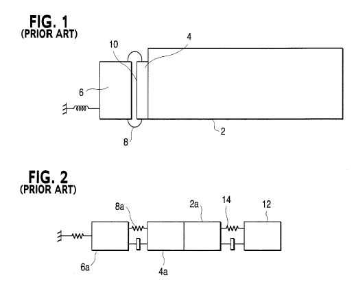

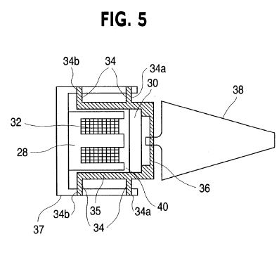
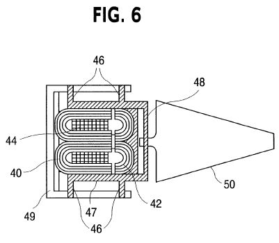
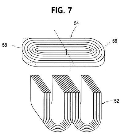
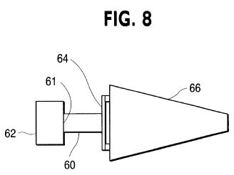
DETAILED DESCRIPTION OF THE PREFERRED EMBODIMENTS
FIG. 3 illustrates an embodiment of the present invention where a power take off (PTO) spring 20 has been added to the prior art device of FIG. 1 between the moving motor mass 18 and resonator 22. In operation, an dynamic force of frequency f is created between motor mass 14 and motor mass 18 which causes motor masses 14 and 18 to oscillate at frequency f in reactive opposition to each other. The periodic displacement of motor mass 18 causes a dynamic force to be transmitted through spring 20 to resonator 22 which in turn causes a periodic displacement of resonator 22 at frequency f. If frequency f is equal to a standing wave mode frequency of the resonator which can be excited by the resonator's motion, then the periodic displacement of resonator 22 will transfer energy to that mode.
FIG. 4 provides a lumped element diagram of the embodiment of FIG. 3, comprising motor mass 14a, motor mass 18a, motor spring 16a, PTO spring 20a, resonator mass 22a, fluid spring 24 and fluid mass 26. When a mode of resonator 22 is being driven, the phases between the displacements of all masses 14a, 18a, 22a, and 26 are determined by the respective mass values and by the respective stiffness and damping values of motor spring 16a, PTO spring 20a, and fluid spring 24.
Adjusting the stiffness of PTO spring 20a of FIG. 4 provides a means to tune the mechanical power factor seen by the motor (represented by masses 14a and 18a) as it delivers power to the resonator, thus reducing the motor force required for a given power delivery to the load. PTO spring 20a also prevents rigid coupling of resonator mass 22a with motor mass 18a, thereby making possible designs which reduce the motor force required for a given power delivery to the load. Reducing the required motor force results in reducing energy losses resulting from the motor's transduction efficiency and thus improves the overall efficiency of the power delivery system. Reducing the required motor force also reduces the required size of the motor, thus reducing the amount of motor materials required for a given power delivery to the load.
PTO spring 20a of FIG. 4 allows power factors approaching unity to be achieved without having to tune any of the mechanical resonances, associated with springs 16a and 20a, close the driven acoustic resonance. Thus, component displacements are minimized, noise is reduced, and excessive spring stresses are avoided. Providing high power factors, without the risk of crossing acoustical and mechanical resonance frequencies, eliminates the severe control problems which occur due to resonance repulsion phenomena.
The stiffness of each mechanical spring can be chosen so that (i) the mechanical resonance frequency where motor spring 20a sees its maximum displacement is above the acoustic resonance frequency and (ii) the mechanical resonance frequency where spring 16a sees its maximum displacement is below the acoustic resonance frequency. This design provides two preferred operating characteristics. First, fluid heating may cause the acoustic resonance frequency to increase during operation and this design assures that the acoustic resonance frequency will not cross the mechanical resonance frequency associated with the maximum displacement of spring 16a. Second, provided that the mechanical resonance frequency associated with the maximum displacement of spring 20a is sufficiently above the acoustic resonance frequency so that the two resonances never overlap during operation, then some benefit can be derived. As the acoustic resonance frequency increases, accelerations can also be made to increase thereby transferring more power to the load for the same motor force. Proper selection of component mass and spring stiffness can also cause the power factor measured at the air gap to improve as the acoustic resonance frequency increases.
In general, the addition of PTO spring 20a allows greater system design flexibility, since the properties of each mechanical element are more independent. PTO spring 20a allows tuning of all the relative component displacements, relative displacement phases, and component masses.
The power delivery unit should be resiliently mounted to ground, since each component of the system oscillates. For a given design, the specific acceleration of masses depends on the mass of each component and stiffness and damping of each spring. The mass with the lowest acceleration provides a good point for resilient mounting to ground.
FIG. 5 shows a cross sectional view of a variable reluctance motor used as a two-mass dynamic force motor in accordance with the present invention. The variable reluctance motor consists of a first motor mass 28 formed by a stack of flat "E" laminations rigidly joined together so that the stack forms a single unit, a second motor mass 30 formed by a stack of flat "I" laminations rigidly joined together so that the stack forms a single unit, a conducting coil 32 wound around the center leg of the E lamination stack, leaf springs 34, with levels 34a and 34b, which resiliently join the first and second motor masses 28 and 30 together via carriages 35 and 37, and a PTO leaf spring 36 which resiliently connects the second motor mass 30 to resonator 38. Second motor mass 30 is rigidly connected to carriage 35, and first motor mass 28 is rigidly connected to carriage 37. Carriages 35 and 37 slide back and forth relative to one another. The motor laminations can be constructed of silicon steel laminations which are typically used in transformers. The mass of carriage 35 may be considered to be part of the second moving mass, and the mass of carriage 37 may be considered to be part of the first moving mass. The space between the three legs of the E laminations and the I laminations comprises an air gap 40. The two levels of leaf springs 34, levels 34a and 34b, allow planer relative motion of second motor mass 30 and first motor mass 28 so as to keep the instantaneous air gap 40 everywhere uniform. Single level springs or any other spring topology could also be used which provide planer motion of the components.
In operation, when an alternating current is established in coil 32 a time varying magnetic flux is created within air gap 40 which is accompanied by a static attractive force and a time varying attractive force between the first and second motor masses 28 and 30. Motor masses 28 and 30 respond to this time varying force by oscillating in reactive opposition to each other. Leaf springs 34 provide a bias force to prevent the attractive force from drawing motor masses 28 and 30 together while still allowing them to oscillate. The periodic oscillation of motor mass 30 applies a dynamic force through PTO spring 36 to resonator 38, thus causing resonator 38 to oscillate along its cylindrical axis. If the oscillation frequency of resonator 38 is equal to one of the standing wave mode frequencies which can be excited by the resonator's motion, then the periodic displacement of resonator 22 will transfer energy into that mode. Variable reluctance motors provide high energy efficiency when small displacements and large forces are required, which is typically the case for acoustic resonators.
FIG. 6 shows a variable reluctance motor used as a two-mass dynamic force motor in accordance with the present invention, which reduces the portion of total magnetic losses caused by non-grain oriented magnetic flux. The variable reluctance motor consists of a first motor mass 40 formed by tape-wound laminations and joined to each other so as to form a single unit, a second motor mass 42 formed by tape-wound laminations and joined to each other so as to form a single unit, a conducting coil 44 wound around the center leg of the first motor mass, leaf springs 46 which resiliently join the first and second motor masses 40 and 42 together via carriages 47 and 49, and a PTO leaf spring 48 which resiliently connects the second motor mass 42 to resonator 50. The mass of carriage 47 may be considered to be part of the second moving mass, and the mass of carriage 49 may be considered to be part of the first moving mass. In operation the motor of FIG. 6 operates in the same manner as the motor of FIG. 5.
FIG. 7 illustrates an alternative magnetic structure for a variable-reluctance motor having first motor mass 52 formed of two tape-wound laminations and a second motor mass 54 formed of a single tape-wound lamination. While second motor mass 54 does not prevent cross-grain field orientation, it does provide a simple and very rigid structure having ends 56 and 58 which provide convenient connection points for springs, carriages or other hardware. Many combinations of tape-wound and stacked flat lamination components can be combined based on given design requirements and will suggest themselves to those skilled in the art.
The PTO spring of the present invention can be used in combination with any type of dynamic force motor. All motors may be thought of as providing a dynamic force to a member causing some movement in that member, however small. Thus, all the motors, including all motors described herein are dynamic force motors.
FIG. 8 describes another type of dynamic force motor. FIG. 8 illustrates an embodiment of the present invention having a PTO spring 64 with one end connected to a flexing dynamic force motor 60 and the other end connected to a resonator 66. Reaction mass 62 is preferably rigidly connected to flexing dynamic motor 60 at an end 61 thereof. Reaction mass 62 may be also be resiliently connected to flexing dynamic motor 60 at end 61, and in this case it is preferred that the resilient connection be relatively stiff compared to the spring constant or stiffness of PTO spring 64. Flexing dynamic motor 60 can be a piezoelectric element, a magnetostrictive element, or any other element which provides a dynamic force by periodically flexing or changing its overall dimensions.
In operation motor 60 of FIG. 8 undergoes a periodic change in its dimension thus creating a dynamic force of frequency f which is communicated to resonator 66 through PTO spring 64. In embodiments in which the dynamic force motor 60 has a small mass relative to that of the reaction mass 62, the force of the motor 60 is effectively transferred to the resonator 66 by virtue of the reaction mass 62 and PTO spring 64 which causes the periodic displacement of resonator 66 at frequency f. Reaction mass 62 prevents excessive accelerations of the reaction mass end 61 of motor 60 and maximizes the force of motor 60 applied to PTO spring 64. If the frequency f is equal to a standing wave mode frequency of the resonator which can be excited by the resonator's motion, then the periodic displacement of resonator 66 will transfer energy into that mode. The embodiment of FIG. 8 can be operated without PTO spring 64 by rigidly connecting motor 60 to resonator 66. However, this would eliminate the advantages described above.
It may be seen that the embodiments of the invention utilize the PTO spring as the exclusive mechanism to couple the active force components of the motor to the resonator. Thus, the moving elements of the motor which are effective in causing oscillation of the resonator are isolated from the resonator by the resilient coupling mechanism, i.e., the PTO spring. In contrast, prior art devices couple the motor to the resonator by a rigid connection and do not utilize a PTO spring as the primary force path from the motor to the resonator.
While the above description contains many embodiments of the invention, these should not be construed as limitations on the scope of the invention, but rather as an exemplification of preferred embodiments thereof. Other embodiments which will occur to those skilled in the art are within the scope of the present invention. For example, any motor which generates a dynamic force can be employed such as off-concentric rotational motors, electrodynamic motors, and electromagnetic motors. Variable reluctance motors need not use only laminations but can be formed from pressed materials that have multidirectional grain properties so as to avoid off-axis grain magnetic losses. The springs may comprise any spring type which accommodates a particular design such as coil springs, leaf springs, bellville springs, magnetic springs, gas springs or other devices that provide a resilient coupling. The fluids within the resonators of the present invention can be either liquids or gases. Any type of acoustic resonator can be used including cylindrical resonators or Resonant Macrosonic Synthesis (RMS) resonators of any shape as described for example in U.S. Pat. Nos. 5,515,684, 5,319,938, and 5,174,130 the entire contents of which are hereby incorporated by reference.
It should further be appreciated that an excited resonance mode of the resonator may generally take place anywhere on the resonance response curve as, for example, at full or near full power, at half power points, quarter power points or the like. Thus a resonant mode can be excited over a range of frequencies.
The scope of the present invention is not limited to particular applications of the acoustic resonator to which power is delivered. For example the present invention can be applied to acoustic resonators for oil-less acoustic compressors and pumps for air compression, refrigeration, comfort air-conditioning, hazardous fluids, ultra-pure fluids, natural gas, and commercial gases; acoustic resonators for process control; acoustic resonators used as process reactors for chemical and pharmaceutical industries; acoustic resonators for separation of gases including pressure swing adsorption; and acoustic resonators for agglomeration, levitation, mixing, and pulverization to name a few. Such applications may or may not include RMS resonators. While omitted for clarity, such applications of the invention may utilize inlet/outlet valves and heat exchange apparatus as shown in FIG. 13 of U.S. Pat. No. 5,319,938 and FIG. 16 of U.S. Pat. No. 5,515,684.
Accordingly, the scope of the invention should be determined not by the embodiments illustrated, but by the appended claims and their equivalents.
US6163077
RMS energy conversion
RMS energy conversion
An energy conversion device comprises an acoustic resonator, a pulse combustion device for creating a standing wave within said resonator, and an electric alternator. The alternate is coupled to the resonator to convert acoustically driven mechanical vibrations into electrical power.
BACKGROUND OF THE INVENTION
1) Field of Invention
This invention relates to Resonant Macrosonic Synthesis (RMS) resonators which are either pulse combustion driven or thermoacoustically driven for the purpose of energy conversion, having specific applications to electric power production.
2) Description of Related Art
History reveals a rich variety of technologies conceived for the purpose of electric power production. Of particular interest are those technologies designed to combust liquid or gaseous fuels in order to produce electric power.
Many types of internal combustion engines have been employed which convert the chemical potential energy of fuels into mechanical energy which is used to drive an electric alternator. However, internal combustion engines need frequent periodic maintenance and provide low conversion efficiencies. Currently, turbines provide the most efficient conversion of fuels, such as natural gas, into electric power. The design and manufacturing sophistication which is inherent in turbine technology can be seen in both their initial cost and operating cost.
Some effort has been directed to the field of standing acoustic waves as a means of electric power production. For example, it was suggested by Swift that the oscillating pressure of thermoacoustically driven standing waves could be utilized for driving an alternator to produce electric power (G. W. Swift, "Thermoacoustic Engines," J. Acoust. Soc. Am. 84, 1166 (1988)). This would be accomplished by coupling a piston to an open end of the acoustic resonator and allowing the vibrating piston to drive a linear alternator The piston would require a gas seal such as a diaphragm or bellows which raises issues of reliability. Moving pistons also limit the dynamic force which can be extracted from the standing wave, thereby limiting the thermoacoustic generator's efficiency.
Another application of standing acoustic waves to the production of electric power was reported by Swift which exploited Magneto Hydrodynamic effects in a thermoacoustically driven liquid sodium standing wave engine (G. W. Swift, "Thermoacoustic Engines," J. Acoust. Soc. Am. 84, 1169 (1988)).
Pulse combustion (PC) is a further field of research where electric power production has been proposed in connection with standing acoustic waves. Other than Magneto Hydrodynamics the PC field has apparently received little attention as a means of producing electric power. Considerable research and development has occurred in the PC field dating back to the previous century. In the early 1920s pulse combustors first received attention as a means to drive electric power producing turbines as seen in U.S. Pat. No. 1,329,559 to Nikola Tesla. Most of the applications research performed today relates to producing either heat or propulsive thrust. For these applications, pulse combustors have always been comparatively attractive, due to their self-sustaining combustion cycle, inherent simplicity, and low production of pollutants. Putnam, Belles, and Kentfield provide a comprehensive history of pulse combustor development showing many of the embodiments and applications in the art of pulse combustion (A. A. Putnam, F. E. Belles, and J. A. C. Kentfield, "Pulse Combustion," Prog. Energy Combust. Sci. 12, 43-79 (1986)). The field of PC research is very active with significant efforts taking place at institutions such as the Gas Research Institute, Sandia Combustion Labs, and various universities.
In summary, thermoacoustic engines have been proposed as a means of driving piston-actuated electric alternators to produce electric power.
However, the concept is in need of certain optimizations, practical improvements, and simplifications. Little effort has been directed toward developing a practical system for utilizing PC-driven standing waves as a means of electric power production. When compared to contemporary technologies, such as gas turbines, a PC electric power generator would provide a fuel-to-electric conversion system of extraordinary simplicity.
SUMMARY OF THE INVENTION
It is an object of the present invention to provide pulse combustion (PC) driven acoustic resonators whose vibratory motion is used to drive an electric alternator.
A further object of the present invention is to employ resonant macrosonic synthesis (RMS) resonators as a PC chamber in order to maximize the acoustic reaction force for a given fuel consumption rate, thereby improving fuel-to-electric transduction efficiency.
A still further object of the present invention is to increase the power density of a PC by providing tuned induction as well as pre-heating and premixing of the combustion reactants.
An even further object of the present invention is to provide a comparatively inexpensive technology for converting fuels such as natural gas into electric power.
An additional object of the present invention is to provide needed optimizations and practical improvements to thermoacoustic electric power generators.
These and other objects and advantages of the invention will become apparent from the accompanying specifications and drawings, wherein like reference numerals refer to like parts throughout.
DETAILED DESCRIPTION OF DRAWINGS
FIG. 1A shows an alternate embodiment of the embodiment of FIG. 1.
FIG. 1 is a sectional view of a pulse combustion electric power generator in accordance with the present invention;
FIG. 2 is a graphical representation of the fundamental mode's peak pressure distribution corresponding to resonator 2 of FIG. 1;
FIG. 3 is a graphical representation of a pressure-time waveform which can be provided by RMS resonators having certain advantages for the present invention;
FIG. 4 is a sectional view of a pulse combustion electric power generator in accordance with the present invention having a resonator geometry which increases the acoustically-driven dynamic forces on the resonator;
FIG. 5 is a graphical representation of the fundamental mode's peak pressure distribution corresponding to resonator 32 of FIG. 4;
FIG. 6 is a sectional view of a pulse combustion electric power generator in accordance with the present invention having tuned induction compressors and reactant pre-combustion mixing;
FIG. 7 is a graphical representation of the static and dynamic pressures associated with the induction compressors of FIG. 6.
FIG. 8 is a sectional view of a thermoacoustically driven electric power generator in accordance with the present invention.
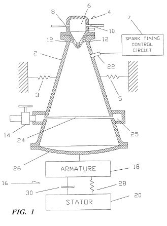
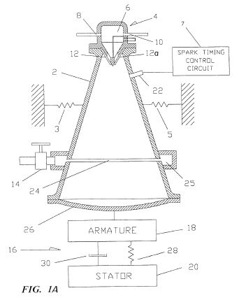
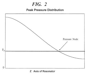


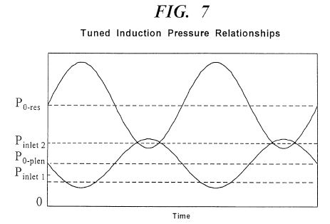
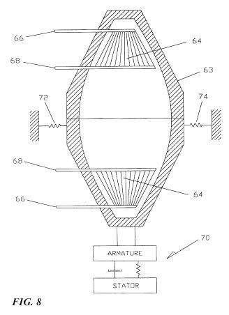
DETAILED DESCRIPTION OF THE PREFERRED EMBODIMENTS
Acoustically driven structural vibration of the combustion chamber (the resonator) is typically an unwanted byproduct of PC operation. Considerable research is directed toward minimizing this unwanted effect. In contrast, the present invention exploits these vibrations as a means of creating electric power by allowing the entire resonator to be driven back and forth in response to the standing wave's dynamic pressure.
FIG. 1 shows an embodiment of the present invention where a RMS resonator 2 is provided, which is resiliently mounted to the stationary surrounding environment by springs 3 and 5 thereby being unrestrained and free to vibrate along its cylindrical axis z. Resonator 2 has a rigid end wall 26, an annular exhaust port 24, annular exhaust plenum 25, optional throttle valve 14, spark plug 22, and a valve head 4. Valve head 4 comprises a fuel-oxidizer plenum 6, a fuel inlet 8, an oxidizer inlet 10 and reactant inlet valves 12.
Connected to resonator 2 is alternator 16 comprising armature 18 which is rigidly connected to resonator 2 and stator 20 which is resiliently connected to armature 18. The resilient connection is shown schematically as spring 28 and damper 30. The term stator is not used here to imply that stator is stationary. On the contrary, stator 20 can be unrestrained and free to vibrate or alternatively it can be rigidly restrained. Optionally, armature 18 could be spring mounted to resonator 2 in order to provide further control of the relative vibrational phases of stator 20, armature 18, and resonator 2.
Many methods exist for starting pulse combustors and spark plug 22 provides one such approach. In operation, spark plug 22 creates a spark which initiates the combustion of the fuel-oxidizer mixture inside resonator 2. This initial combustion starts the well known self-sustaining PC cycle which is driven by the resultant oscillating pressure inside resonator 2. Once started, the spark plug can be deactivated and the PC system will run at its characteristic resonant frequency.
Other methods can be used to vary the resonant frequency such as a spark timing control circuit 7 in FIG. 1 and rotary valves both of which are per say well known. Variably-tuned resonator branches could also be used to vary the resonant frequency. For example, a variably tuned branch could comprise a narrow cylindrical tube having one end which opens into the combustion resonator and the other end fitted with a tuning piston. The resonant frequency of the combustion chamber could be varied by sliding the tuning piston within the tube.
Combustion products exit resonator 2 through annular port 24 which must have sufficient flow area to support the design exhaust flow rate. FIG. 2 illustrates the fundamental mode's peak pressure distribution along the length of resonator 2, where z is its axi-symmetric axis for which z=0 at the narrow end and z=L at the wide end. Although port 24 can be placed anywhere within the walls of resonator 2, the preferred placement corresponds to the fundamental's pressure node shown in FIG. 2 which will tend to minimize the transmission of dynamic pressure through port 24. If dynamic pressure is transmitted through port 24, then it can no longer be converted into useable force as described below. In general, exhaust port placement should be chosen so as to maximize the resonator's internal dynamic pressure. Port 24 could be fitted with optional throttle valve 14 or could be equipped with compressor-type discharge valves such as reed valves or plate valves which would open in response to the pressure difference across the valve.
Once the standing wave is established its oscillating pressure exerts dynamic forces against the inner walls of resonator 2 causing it to vibrate as a rigid body along the z direction at the acoustic frequency. Armature 18 is attached to resonator 2 and so is set into vibration with it. The resulting relative motion of armature 18 and stator 20 will create electric power in a manner determined by the generator's topology. In the preferred embodiment, stator 20 is not stationary but free to move at some phase angle with respect to the motion of armature 18. Alternator 16 could be a voice coil alternator, a variable reluctance alternator as shown in U.S. Pat. No. 5,174,130 the entire contents of which are hereby incorporated by reference, an alternator as shown in U.S. Pat. No. 5,389,844 the entire contents of which are hereby incorporated by reference, or any other of a great number of linear alternators. Other designs that could be employed, but which lack a literal armature and stator, include piezoelectric and magnetostrictive alternators. Alternator selection will reflect the specific design requirements including frequency of operation, the resonator's vibrational displacement amplitude, and transduction efficiency between mechanical and electrical power.
The characteristics of the resilient mounting, shown schematically as spring 28 and damper 30, between armature 18 and stator 20 will affect the transduction efficiency of the system. Optimal power factors can be found by modeling the system dynamics and accounting for all the moving masses, springs and damping in the system. The specific analytical model will reflect the type of alternator employed by the system.
The resistance presented to the exhaust flow by port 24, plenum and optional throttle valve 14 will influence the average pressure P0 upon which the dynamic pressure is superimposed as shown in FIG. 2. Other factors influencing the average pressure P0 will include the inlet flow resistances, the fluid properties, and the resonator geometry. Throttle valve 14 can be used to adjust the exhaust flow resistance and thus vary the average pressure P0. Increasing the outlet flow resistance will increase P0 and decreasing the outlet flow resistance will reduce P0. For a given power input, increasing P0 will generally increase the peak-to-peak dynamic pressure, thereby increasing the dynamic forces on the resonator, resulting in increased electric power output. Thus, in order to maximize fuel-to-electric transduction efficiency the average pressure P0 should be as high as possible as long as the negative peak pressure -P does not rise above the reactant supply pressure which would interrupt the intake of fresh reactants. If discharge valves are used in combination with port 24, then both the flow area of the valve system and the valve's spring loading, if any, will influence P0. Alternatively, compressor-type dynamic discharge valves could be located at z=0 where discharge pressures are higher resulting in reduced exhaust volume flow rates, as shown by FIG. 1A as element 12as.
Preferred embodiments of the present invention use the resonator's first longitudinal mode as illustrated by FIGS. 1 and 2 in order to maximize the reaction forces and thus the fuel-to-electric transduction efficiency as described. Alternatively, rigid wall 26 could be resiliently attached to resonator 2 with a flexible seal, such as a bellows, which would allow wall 26 to vibrate independently of resonator 2. Resonator 2 could be rigidly restrained while allowing wall 26 to vibrate along the z axis in response to the dynamic acoustic pressure, thereby driving armature 18 of alternator 16. Also, Helmholtz type resonators could be used within the scope of the present invention with an alternator also being connected to the resonator as in FIGS. 1 and 4.
Resonator design plays an important role in optimization of the present invention. The particular resonator design chosen will determine the dynamic pressure amplitude which can be achieved for a given acoustic power input and thus plays an important role in determining the fuel-to-electric transduction efficiency of the present invention. RMS resonators for obtaining unshocked ultrahigh dynamic pressures with specific predetermined waveforms are described in U.S. Pat. Nos. 5,515,684 and 5,319,938 and their divisional and continuing applications, the entire contents of which are hereby incorporated by reference.
In general, the vibrating resonator can provide large amounts of vibrational mechanical power that can be used to drive an electrical alternator, as previously described, or it can be used as a linear motor for many other applications. Linear motors are widespread and their uses are well known to those skilled in the art.
The extremely high amplitude shock-free dynamic pressures of RMS resonators can provide another important advantage for pulse combustors. RMS resonators can provide compression ratios high enough for compression-ignition (CI). Pulse combustors commonly rely on the existence of a residual flame to cause ignition after fresh reactant intake has occurred. If at any time the residual flame is extinguished, then the pulse combustor will cease to operate. Operating in CI mode eliminates the need to maintain a residual flame inside the combustor chamber, thus providing a more robust combustion cycle.
RMS resonators can provide air compressions from 1 atmosphere to over 230 psig. An acoustic compression is isentropic and thus can provide significant increases in air temperature. For example, an isentropic compression of 27 DEG C. air from 1 atmosphere to 100 psig will raise the air temperature beyond the ignition temperature of propane. With approximately 100 DEG C. of preheat, this same isentropic 100 psig air compression can reach the ignition temperature for methane. When predicting the amount of preheat needed for CI to occur the already high temperatures of the gas within the combustion chamber must be taken into consideration. These high ambient gas temperatures can cause significant heat transfer to the incoming reactants and thus reduce the amount of preheat required.
Depending on the type of fuel used it may be necessary to use air and/or fuel preheating, or a catalyst inside the resonator, to initiate compression ignition if a low compression ratio is desired by the designer. The addition of small amounts of a secondary fuel (e.g. diesel) with a lower ignition Temperature can also be used to provide CI of fuels like methane at low compression ratios.
RMS pulse combustors can be operated in either residual flame mode or CI mode. In either mode, fuel injection can be used, instead of pressure operated reed valves, to control the timing of when fuel is introduced into the pulse combustor. As shown in FIG. 1 pressure actuated flapper valves can be used to admit combustion reactants into the combustion chamber. Of course, air preheat is also an important ignition timing variable regardless of whether flapper valves or fuel injection is used.
Regardless of the exact design chosen, combustion must first be initiated by a spark plug, glow plug, or other means. For CI operation, a spark plug can be used to control the initial combustion timing during start-up transients when the dynamic pressure is to low to reach ignition temperatures.
One of the advantages of operating in CI mode is that complete combustion does not depend on the characteristic time delays of flame propagation. In CI mode complete energy release from the fuel can occur much faster and thus the pulse combustor can run at higher frequencies. This allows a pulse combustor of given power output to be downsized, thus increasing its power density and reducing its cost. Further increases in power density could be made by using hydrogen as a fuel due to its comparatively fast combustion. Hydrogen would also provide the environmental advantages of not producing the combustion products associated with hydrocarbon fuels.
In addition to providing ultrahigh dynamic pressures, RMS resonators offer other advantages derived from waveform synthesis. For example, FIG. 3 shows an RMS resonator waveform that provides .vertline.-.vertline.>.vertline.+P.vertline., where .vertline.-P.vertline..tbd.P0 +(-P) and .vertline.+P.vertline..tbd.(+P)-P0. This waveform will allow the pulse combustor to run at a higher average pressure P0 while still keeping the negative peak pressure -P below the reactant supply pressure so that the reactant flow is not interrupted. As explained, running higher P0 values improves the fuel-to-electric energy transduction efficiency. To those skilled in the art, RMS resonators will provide numerous enhancements to the present invention all of which are considered to be within the scope of the present invention.
Another consideration for maximizing P0 is the placement of inlet valves 12 in FIG. 1. The small diameter end of resonator 2 will provide the largest dynamic pressures and thus the lowest negative peak pressure -P for a given value of P0. Consequently, this valve placement allows the PC to operate at the highest P0 value with all of the advantages cited above. Optionally, the valves could be placed at any other location within the walls of the resonator where the dynamic pressure of the fundamental exists.
FIG. 4 illustrates an embodiment of the present invention employing a RMS resonator 32 whose longitudinal symmetry increases the acoustic forces on the resonator created by the fundamental mode's pressure distribution. The curvature of resonator 32 is determined by D(z)=Dth +k[sin(.pi.z/L)], where D is the diameter, Dth is the throat or starting diameter, z is the axi-symmetric axis of resonator 32, k is a weighting coefficient and L is the resonator's total axial length. Alternatively, the curvature of resonator 32 could be described by any number of other functions including hyperbolic, parabolic or elliptical all of which will give different force characteristics.
Resonator 32 is resiliently mounted to the stationary surrounding environment by springs 35 and 37 thereby being unrestrained and free to vibrate along its cylindrical axis z. Mounted to each end of resonator 32 are identical valve heads 34 which allow 2 combustion events per acoustic cycle thereby increasing the PC generator's power density. Alternatively, the pulse combustor of FIG. 4 can run with only one valve head at the cost of reduced power density. Resonator 32 has an annular exhaust port 39 and annular exhaust plenum 38 whose functions are identical to annular exhaust port 24 and annular exhaust plenum 25 of FIG. 1. A generator 40 is shown schematically which converts the z axis vibration of resonator 32 into electric power as described above in relation to FIG. 1.
FIG. 5 shows the peak pressure distribution of the fundamental mode along the length of resonator 32, where z is its axi-symmetric axis and +P is the positive peak pressure and -P is the negative peak pressure. For the fundamental mode, the local z components of the inner surface area are directed so that all the local products of pressure and area at any time will produce forces on the resonator walls having the same z axis direction. This condition will hold as long as dr/dz changes mathematical sign wherever the peak pressure distribution changes mathematical sign. For resonator 32 this condition occurs at z=L/2, where L is the resonator length. In addition to z=L/2, there is a continuum of z values at which both dr/dz and the peak pressure distribution can be made to change sign together.
The relative dimensions of resonator 32 can be adjusted to further increase the acoustically exerted forces by changing the maximum-to-minimum diameter ratio. For resonator 32, the maximum diameter occurs at z=L/2, and the minimum diameter occurs at z=0 and z=L, where the diameter=Dd,. For example, if the max/min diameter ratio of resonator 32 begins at 1.7 and is increased a factor of 7, then the force increases by a factor of 40. This assumes that the peak-to-peak dynamic pressure, as measured at Dth remains the same for both cases.
Under some circumstances air, or a given oxidizer, must first be forced under pressure into the resonator before the reactants can be ignited. This same starting method will work with the present invention.
Another starting scheme for the present invention is to use the alternator as a starting motor so that the PC generator is temporarily operated as an acoustic compressor. In start mode, an alternating voltage is applied to the motor which then drives the resonator back and forth thereby exciting its fundamental resonant mode. The valves respond to this mechanically-driven dynamic pressure and reactants are drawn into the combustion chamber at which time an applied spark can initiate the PC cycle. To avoid abruptly switching from motor to alternator mode, the motor could be switched off just prior to the firing the ignition spark. Once the PC cycle is started the motor is switched back to alternator mode, and electric power is provided as described above.
As explained, large P0 values increase the PC generator's efficiency and power density. FIG. 6 illustrates another embodiment of the present invention which provides even higher P0 values by means of tuned induction compressors for induction ramming. The embodiment of FIG. 6 also provides reactant preheating and thorough premixing. These features promote high efficiency due to complete burning of reactants as well as rapid burn rates for high frequency operation.
In FIG. 6 a resonator 42 is provided whose internal geometry is similar in form and function to resonator 32 of FIG. 4. Resonator 42 is resiliently mounted to the stationary surrounding environment by springs 53, 55, 57, and 59 thereby being unrestrained and free to vibrate along its cylindrical axis z. Resonator 42 has spark plug 43, annular exhaust port 44 and annular exhaust plenum 46 whose functions are identical to annular exhaust port 39 and annular exhaust plenum 38 of FIG. 4. Mounted to each end of resonator 42 are identical acoustic induction compressors 48 consisting of tuned plenums 50, first stage valves 52 and second stage valves 54. Plenums 50 are designed so as to have approximately the same resonance frequency as resonator 42. Identical heat exchanger cowlings 56 are provided with fuel inlets 58 and oxidizer inlets 60. Cowlings 56 need not be rigidly attached to resonator 42 but must at least form a seal with resonator 42 to prevent reactant leakage. If cowlings 56 were resiliently mounted so that they need not vibrate with resonator 42, then they could provide both heat insulation and noise suppression. Also, a single inlet could be provided in each cowling for fuel and oxidizer rather than the two respective openings shown.
Many alternator topologies can be annularly configured so as to wrap around resonator 42. For example, FIG. 6 shows a variable reluctance alternator 45 which is wrapped annularly around resonator 42. Alternator 45 has annular armature 47 which is rigidly connected to flange 62 of resonator 42, annular stator 49 which is resiliently connected to armature 47 via annular spring 51 and annular linkage 61, drive coil 65 within annular stator 49, and drive coil leads 67. Dynamically, alternator 45 will respond to the z axis vibration of resonator 42 in the same manner as alternator 16 of FIG. 1 responds to the z axis vibration of resonator 2.
FIG. 7 illustrates the dynamic and static pressure relationships of the various stages of compression. In operation, the pulse combustion driven standing wave is initiated by spark plug 43. Reactant flow proceeds through inlets 58 and 60 at the inlet pressure Pinlet-1 and through cowlings 56 where the reactants pick up heat from the wall of resonator 42 and experience some degree of flow mixing. The vibration of the entire generator assembly will excite the fundamental resonance of tuned plenums 50. The resulting dynamic pressure inside tuned plenums 50 will draw in the heated reactants from cowling 56 through valves 52 and into tuned plenums 50 thereby compressing the reactants to the average plenum pressure P0-plenum. Inside tuned plenums 50 the reactants experience further mixing due to the initial turbulent valve flow and then due to the cyclic acoustic particle displacement.
The dynamic pressure inside plenums 50 will compress the reactants again from the average plenum pressure P0-plenum up to the plenum discharge pressure Pinlet-2 at which time the reactants are discharged from plenums 50 through the 2@nd stage valves 54 and into resonator 42. The overlap of the plenum's peak acoustic pressure and the minimum acoustic pressure of resonator 42 forces second stage valves 54 open once per cycle thereby discharging the heated and mixed reactants into resonator 42 for combustion. The passage of reactants through valves 54 induces further mixing. The result of this process as seen in FIG. 7 is an elevated average resonator pressure P0-res due to the pressure lift provided by induction compressors 48.
Additional induction compressors could be staged if desired to provide even higher P0-res values. Cowlings 56 also lend themselves to acoustical resonance and could provide additional dynamic pressure boost.
Consideration must be given to the acoustic design of resonant plenums 50. As shown in FIG. 7, the phase between the plenum's standing wave and the resonator's standing wave is essential to the compression process. The plenum's resonance is driven by two sources: the opening of 2@nd stage valves 54 and the vibratory motion of the entire plenum. The superposition of these two driving sources must be taken into account when designing the plenum geometry. If the plenum resonant frequency is to be equal to the resonator's, then the plenum design should ensure that the valves are the weaker source.
Many improvements on the embodiment of FIG. 6 will suggest themselves to those skilled in the art of tuned compressor or engine plenums and pulse combustors. For example, the plenums could be tuned to the resonator's 2@nd harmonic in which case the 2@nd stage valves could act as the sole driving source and the proper phases for induction ramming would be provided. Further, the ratio of 1@st and 2@nd stage valve areas can be used to increase P0-plenum and therefor P0-res. Still further, if premixing of the reactants inside cowlings 56 is objectionable for safety reasons, then individual oxidizer and fuel cowlings can be used which would keep the reactants separated up to the induction compressors. Similarly, individual fuel and oxidizer lines could be wrapped in annular fashion around the exterior of resonator 42, thereby being placed in thermal contact with the hot resonator walls.
If a gaseous fuel supply pressure is high enough, then induction compressors 48 could be used to compress only the oxidizer and the fuel could be provided through a typical gas distributor within resonator 42.
Electrically-driven motors are commonly used to drive standing wave compressors as is well known in the art. These electric motors supply the oscillating force needed for entire resonator drive. The induction compressors of the present invention are in fact standing wave compressors. As described above the pulse combustor of the present invention can be used to directly drive these induction, or standing wave, compressors by means of entire resonator drive and is referred to herein as engine-drive. In the same manner, the is engine-drive can be used to drive a standing wave compressor for any application, such as refrigeration and air-conditioning, air compression, acoustic vacuum pumps, compression of commercial gases, compression of natural gas, to name a few. In general, engine-drive can be used to drive a RMS resonator for any of the many RMS applications.
As an alternative to PC, the standing acoustic waves of the present invention can be driven thermoacoustically. As described, current proposals for thermoacoustically driven electric generators require the coupling of a piston to an open end of the acoustic resonator and allowing the vibrating piston to drive a linear alternator. This piston would require a gas seal such as a diaphragm or bellows which raises issues of reliability. The dynamic forces produced by this system are limited by acoustic pressure amplitude and by the surface area of the piston.
Rather than being limited by a piston's surface area, the present invention utilizes the entire inner surface area of the resonator and so can generate very large dynamic forces. The use of RMS resonators further increases the desired dynamic forces by providing extremely high dynamic pressures.
FIG. 8 illustrates a thermoacoustically-driven embodiment of the present invention. An explanation of thermoacoustic engine fundamentals can be found in G. W. Swift, "Thermoacoustic Engines," J. Acoust. Soc. Am. 84, 1169 (1988). In FIG. 8, a rigid walled resonator 63 having heat plate stacks 64 is operated in the prime mover mode as is well known in the art of thermoacoustic engines. Resonator 63 is resiliently mounted to the stationary surrounding environment by springs 72 and 74 thereby being unrestrained and free to vibrate along its cylindrical axis z. Heat is applied at heat exchangers 66 and extracted at heat exchangers 68 so as to provide a temperature gradient along the plate stack sufficient for driving the standing acoustic wave. Once the standing wave is established its oscillating pressure exerts dynamic force, against the walls of resonator 63 causing it to vibrate as a rigid body along z at the acoustic frequency in response to these dynamic forces. As before, a generator 70 is shown schematically which converts the z axis vibration of resonator 32 into electric power.
The art of thermoacoustic engines is well developed and will suggest many methods and techniques to one skilled in the art for implementing the embodiment of FIG. 8. For example, the use of two plate stacks is optional. In addition, plate stacks can be used with RMS resonators to achieve high pressure amplitudes for a desired waveform and with all of the advantages previously described. Further, heat sources used for the embodiment of F IG. 8 could include waste heat from a PC generator of the type described above, waste heat from other processes, direct combustion of fuels as well as solar energy to name a few.
While the above description contains many specifications, these should not be construed as limitations on the scope of the invention, but rather as an exemplification of preferred embodiments. Thus, the scope of the present invention is not limited to specific pulse combustor designs or thermoacoustic designs.
The present invention can be applied wherever electrical power is needed. Frequency locking the PC embodiments of the present invention to the local power grid frequency may be achieved for example with spark timing, the timing of actuated valves such as rotary valves or with variably-tuned resonator branches. In this way, the generated electric power could be linked to the local grid. The AC output from the alternator could be converted to other frequencies or to DC. PC generators could be used as the onboard power source for hybrid electric vehicles, including those that store energy in mechanical flywheels where gas turbines are currently used. The present invention can be sized for various power output requirements.
The PC literature provides a diversity of pulse combustor designs and enhancements including the use of gaseous or liquid fuels, fuel distributor heads, the number of valves used, valved and areovalved combustors, multiple combustors, fuel-oxidizer mixing, valve styles including flappers, Tesla valves, and rotary valves. Many of these concepts can be seen in the following publications: A. A. Putnam, F. E. Belles, and J. A. C. Kentfield, "Pulse Combustion," Prog. Energy Combust. Sci. 12, 43 (1986), J. C. Griffiths, E. J. Weber, "The Design of Pulse Combustion Burners," Research Bulletin 107, American Gas Association Laboratories (1969), P. S. Vishwanath, "Advancement of Developmental Technology for Pulse Combustion Applications," Gas Research Institute Report No. GRI-85/0280 (1985) the entire contents of which are all hereby incorporated by reference. The application of currently available PC design information to the present invention will suggest itself to those skilled in the art.
Accordingly, the scope of the invention should be determined not by the embodiments illustrated, but by the appended claims and their equivalents.
TW374827
RMS energy conversion
RMS energy conversion
BACKGROUND OF THE INVENTION
1) Field of Invention
This invention relates to Resonant Macrosonic Synthesis (RMS) resonators which are either pulse combustion driven or thermoacoustically driven for the purpose of energy conversion, having specific applications to electric power production.
2) Description of Related Art
History reveals a rich variety of technologies conceived for the purpose of electric power production. Of particular interest are those technologies designed to combust liquid or gaseous fuels in order to produce electric power.
Many types of internal combustion engines have been employed which convert the chemical potential energy of fuels into mechanical energy which is used to drive an electric alternator. However, internal combustion engines need frequent periodic maintenance and provide low conversion efficiencies. Currently, turbines provide the most efficient conversion of fuels, such as natural gas, into electric power. The design and manufacturing sophistication which is inherent in turbine technology can be seen in both their initial cost and operating cost.
Some effort has been directed to the field of standing acoustic waves as a means of electric power production. For example, it was suggested by Swift that the oscillating pressure of thermoacoustically driven standing waves could be utilized for driving an alternator to produce electric power (G. W. Swift, "Thermoacoustic Engines," J. Acoust. Soc. Am. 84, 1166 (1988)). This would be accomplished by coupling a piston to an open end of the acoustic resonator and allowing the vibrating piston to drive a linear alternator The piston would require a gas seal such as a diaphragm or bellows which raises issues of reliability. Moving pistons also limit the dynamic force which can be extracted from the standing wave, thereby limiting the thermoacoustic generator's efficiency.
Another application of standing acoustic waves to the production of electric power was reported by Swift which exploited Magneto Hydrodynamic effects in a thermoacoustically driven liquid sodium standing wave engine (G. W. Swift, "Thermoacoustic Engines," J. Acoust. Soc. Am. 84, 1169 (1988)).
Pulse combustion (PC) is a further field of research where electric power production has been proposed in connection with standing acoustic waves. Other than Magneto Hydrodynamics the PC field has apparently received little attention as a means of producing electric power. Considerable research and development has occurred in the PC field dating back to the previous century. In the early 1920s pulse combustors first received attention as a means to drive electric power producing turbines as seen in U.S. Pat. No. 1,329,559 to Nikola Tesla. Most of the applications research performed today relates to producing either heat or propulsive thrust. For these applications, pulse combustors have always been comparatively attractive, due to their self-sustaining combustion cycle, inherent simplicity, and low production of pollutants. Putnam, Belles, and Kentfield provide a comprehensive history of pulse combustor development showing many of the embodiments and applications in the art of pulse combustion (A. A. Putnam, F. E. Belles, and J. A. C. Kentfield, "Pulse Combustion," Prog. Energy Combust. Sci. 12, 43-79 (1986)). The field of PC research is very active with significant efforts taking place at institutions such as the Gas Research Institute, Sandia Combustion Labs, and various universities.
In summary, thermoacoustic engines have been proposed as a means of driving piston-actuated electric alternators to produce electric power.
However, the concept is in need of certain optimizations, practical improvements, and simplifications. Little effort has been directed toward developing a practical system for utilizing PC-driven standing waves as a means of electric power production. When compared to contemporary technologies, such as gas turbines, a PC electric power generator would provide a fuel-to-electric conversion system of extraordinary simplicity.
SUMMARY OF THE INVENTION
It is an object of the present invention to provide pulse combustion (PC) driven acoustic resonators whose vibratory motion is used to drive an electric alternator.
A further object of the present invention is to employ resonant macrosonic synthesis (RMS) resonators as a PC chamber in order to maximize the acoustic reaction force for a given fuel consumption rate, thereby improving fuel-to-electric transduction efficiency.
A still further object of the present invention is to increase the power density of a PC by providing tuned induction as well as pre-heating and premixing of the combustion reactants.
An even further object of the present invention is to provide a comparatively inexpensive technology for converting fuels such as natural gas into electric power.
An additional object of the present invention is to provide needed optimizations and practical improvements to thermoacoustic electric power generators.
These and other objects and advantages of the invention will become apparent from the accompanying specifications and drawings, wherein like reference numerals refer to like parts throughout.
DETAILED DESCRIPTION OF DRAWINGS
FIG. 1A shows an alternate embodiment of the embodiment of FIG. 1.
FIG. 1 is a sectional view of a pulse combustion electric power generator in accordance with the present invention;
FIG. 2 is a graphical representation of the fundamental mode's peak pressure distribution corresponding to resonator 2 of FIG. 1;
FIG. 3 is a graphical representation of a pressure-time waveform which can be provided by RMS resonators having certain advantages for the present invention;
FIG. 4 is a sectional view of a pulse combustion electric power generator in accordance with the present invention having a resonator geometry which increases the acoustically-driven dynamic forces on the resonator;
FIG. 5 is a graphical representation of the fundamental mode's peak pressure distribution corresponding to resonator 32 of FIG. 4;
FIG. 6 is a sectional view of a pulse combustion electric power generator in accordance with the present invention having tuned induction compressors and reactant pre-combustion mixing;
FIG. 7 is a graphical representation of the static and dynamic pressures associated with the induction compressors of FIG. 6.
FIG. 8 is a sectional view of a thermoacoustically driven electric power generator in accordance with the present invention.
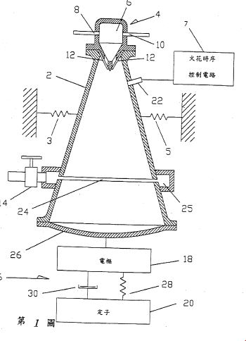
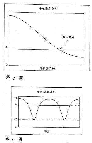
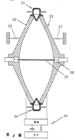
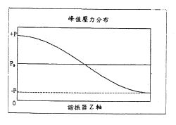
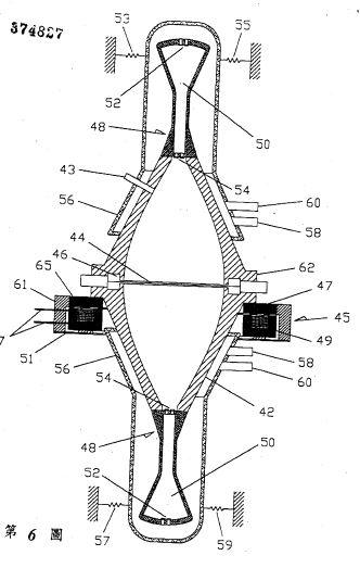

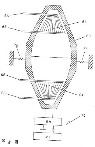
DETAILED DESCRIPTION OF THE PREFERRED EMBODIMENTS
Acoustically driven structural vibration of the combustion chamber (the resonator) is typically an unwanted byproduct of PC operation. Considerable research is directed toward minimizing this unwanted effect. In contrast, the present invention exploits these vibrations as a means of creating electric power by allowing the entire resonator to be driven back and forth in response to the standing wave's dynamic pressure.
FIG. 1 shows an embodiment of the present invention where a RMS resonator 2 is provided, which is resiliently mounted to the stationary surrounding environment by springs 3 and 5 thereby being unrestrained and free to vibrate along its cylindrical axis z. Resonator 2 has a rigid end wall 26, an annular exhaust port 24, annular exhaust plenum 25, optional throttle valve 14, spark plug 22, and a valve head 4. Valve head 4 comprises a fuel-oxidizer plenum 6, a fuel inlet 8, an oxidizer inlet 10 and reactant inlet valves 12.
Connected to resonator 2 is alternator 16 comprising armature 18 which is rigidly connected to resonator 2 and stator 20 which is resiliently connected to armature 18. The resilient connection is shown schematically as spring 28 and damper 30. The term stator is not used here to imply that stator is stationary. On the contrary, stator 20 can be unrestrained and free to vibrate or alternatively it can be rigidly restrained. Optionally, armature 18 could be spring mounted to resonator 2 in order to provide further control of the relative vibrational phases of stator 20, armature 18, and resonator 2.
Many methods exist for starting pulse combustors and spark plug 22 provides one such approach. In operation, spark plug 22 creates a spark which initiates the combustion of the fuel-oxidizer mixture inside resonator 2. This initial combustion starts the well known self-sustaining PC cycle which is driven by the resultant oscillating pressure inside resonator 2. Once started, the spark plug can be deactivated and the PC system will run at its characteristic resonant frequency.
Other methods can be used to vary the resonant frequency such as a spark timing control circuit 7 in FIG. 1 and rotary valves both of which are per say well known. Variably-tuned resonator branches could also be used to vary the resonant frequency. For example, a variably tuned branch could comprise a narrow cylindrical tube having one end which opens into the combustion resonator and the other end fitted with a tuning piston. The resonant frequency of the combustion chamber could be varied by sliding the tuning piston within the tube.
Combustion products exit resonator 2 through annular port 24 which must have sufficient flow area to support the design exhaust flow rate. FIG. 2 illustrates the fundamental mode's peak pressure distribution along the length of resonator 2, where z is its axi-symmetric axis for which z=0 at the narrow end and z=L at the wide end. Although port 24 can be placed anywhere within the walls of resonator 2, the preferred placement corresponds to the fundamental's pressure node shown in FIG. 2 which will tend to minimize the transmission of dynamic pressure through port 24. If dynamic pressure is transmitted through port 24, then it can no longer be converted into useable force as described below. In general, exhaust port placement should be chosen so as to maximize the resonator's internal dynamic pressure. Port 24 could be fitted with optional throttle valve 14 or could be equipped with compressor-type discharge valves such as reed valves or plate valves which would open in response to the pressure difference across the valve.
Once the standing wave is established its oscillating pressure exerts dynamic forces against the inner walls of resonator 2 causing it to vibrate as a rigid body along the z direction at the acoustic frequency. Armature 18 is attached to resonator 2 and so is set into vibration with it. The resulting relative motion of armature 18 and stator 20 will create electric power in a manner determined by the generator's topology. In the preferred embodiment, stator 20 is not stationary but free to move at some phase angle with respect to the motion of armature 18. Alternator 16 could be a voice coil alternator, a variable reluctance alternator as shown in U.S. Pat. No. 5,174,130 the entire contents of which are hereby incorporated by reference, an alternator as shown in U.S. Pat. No. 5,389,844 the entire contents of which are hereby incorporated by reference, or any other of a great number of linear alternators. Other designs that could be employed, but which lack a literal armature and stator, include piezoelectric and magnetostrictive alternators. Alternator selection will reflect the specific design requirements including frequency of operation, the resonator's vibrational displacement amplitude, and transduction efficiency between mechanical and electrical power.
The characteristics of the resilient mounting, shown schematically as spring 28 and damper 30, between armature 18 and stator 20 will affect the transduction efficiency of the system. Optimal power factors can be found by modeling the system dynamics and accounting for all the moving masses, springs and damping in the system. The specific analytical model will reflect the type of alternator employed by the system.
The resistance presented to the exhaust flow by port 24, plenum and optional throttle valve 14 will influence the average pressure P0 upon which the dynamic pressure is superimposed as shown in FIG. 2. Other factors influencing the average pressure P0 will include the inlet flow resistances, the fluid properties, and the resonator geometry. Throttle valve 14 can be used to adjust the exhaust flow resistance and thus vary the average pressure P0. Increasing the outlet flow resistance will increase P0 and decreasing the outlet flow resistance will reduce P0. For a given power input, increasing P0 will generally increase the peak-to-peak dynamic pressure, thereby increasing the dynamic forces on the resonator, resulting in increased electric power output. Thus, in order to maximize fuel-to-electric transduction efficiency the average pressure P0 should be as high as possible as long as the negative peak pressure -P does not rise above the reactant supply pressure which would interrupt the intake of fresh reactants. If discharge valves are used in combination with port 24, then both the flow area of the valve system and the valve's spring loading, if any, will influence P0. Alternatively, compressor-type dynamic discharge valves could be located at z=0 where discharge pressures are higher resulting in reduced exhaust volume flow rates, as shown by FIG. 1A as element 12as.
Preferred embodiments of the present invention use the resonator's first longitudinal mode as illustrated by FIGS. 1 and 2 in order to maximize the reaction forces and thus the fuel-to-electric transduction efficiency as described. Alternatively, rigid wall 26 could be resiliently attached to resonator 2 with a flexible seal, such as a bellows, which would allow wall 26 to vibrate independently of resonator 2. Resonator 2 could be rigidly restrained while allowing wall 26 to vibrate along the z axis in response to the dynamic acoustic pressure, thereby driving armature 18 of alternator 16. Also, Helmholtz type resonators could be used within the scope of the present invention with an alternator also being connected to the resonator as in FIGS. 1 and 4.
Resonator design plays an important role in optimization of the present invention. The particular resonator design chosen will determine the dynamic pressure amplitude which can be achieved for a given acoustic power input and thus plays an important role in determining the fuel-to-electric transduction efficiency of the present invention. RMS resonators for obtaining unshocked ultrahigh dynamic pressures with specific predetermined waveforms are described in U.S. Pat. Nos. 5,515,684 and 5,319,938 and their divisional and continuing applications, the entire contents of which are hereby incorporated by reference.
In general, the vibrating resonator can provide large amounts of vibrational mechanical power that can be used to drive an electrical alternator, as previously described, or it can be used as a linear motor for many other applications. Linear motors are widespread and their uses are well known to those skilled in the art.
The extremely high amplitude shock-free dynamic pressures of RMS resonators can provide another important advantage for pulse combustors. RMS resonators can provide compression ratios high enough for compression-ignition (CI). Pulse combustors commonly rely on the existence of a residual flame to cause ignition after fresh reactant intake has occurred. If at any time the residual flame is extinguished, then the pulse combustor will cease to operate. Operating in CI mode eliminates the need to maintain a residual flame inside the combustor chamber, thus providing a more robust combustion cycle.
RMS resonators can provide air compressions from 1 atmosphere to over 230 psig. An acoustic compression is isentropic and thus can provide significant increases in air temperature. For example, an isentropic compression of 27 DEG C. air from 1 atmosphere to 100 psig will raise the air temperature beyond the ignition temperature of propane. With approximately 100 DEG C. of preheat, this same isentropic 100 psig air compression can reach the ignition temperature for methane. When predicting the amount of preheat needed for CI to occur the already high temperatures of the gas within the combustion chamber must be taken into consideration. These high ambient gas temperatures can cause significant heat transfer to the incoming reactants and thus reduce the amount of preheat required.
Depending on the type of fuel used it may be necessary to use air and/or fuel preheating, or a catalyst inside the resonator, to initiate compression ignition if a low compression ratio is desired by the designer. The addition of small amounts of a secondary fuel (e.g. diesel) with a lower ignition Temperature can also be used to provide CI of fuels like methane at low compression ratios.
RMS pulse combustors can be operated in either residual flame mode or CI mode. In either mode, fuel injection can be used, instead of pressure operated reed valves, to control the timing of when fuel is introduced into the pulse combustor. As shown in FIG. 1 pressure actuated flapper valves can be used to admit combustion reactants into the combustion chamber. Of course, air preheat is also an important ignition timing variable regardless of whether flapper valves or fuel injection is used.
Regardless of the exact design chosen, combustion must first be initiated by a spark plug, glow plug, or other means. For CI operation, a spark plug can be used to control the initial combustion timing during start-up transients when the dynamic pressure is to low to reach ignition temperatures.
One of the advantages of operating in CI mode is that complete combustion does not depend on the characteristic time delays of flame propagation. In CI mode complete energy release from the fuel can occur much faster and thus the pulse combustor can run at higher frequencies. This allows a pulse combustor of given power output to be downsized, thus increasing its power density and reducing its cost. Further increases in power density could be made by using hydrogen as a fuel due to its comparatively fast combustion. Hydrogen would also provide the environmental advantages of not producing the combustion products associated with hydrocarbon fuels.
In addition to providing ultrahigh dynamic pressures, RMS resonators offer other advantages derived from waveform synthesis. For example, FIG. 3 shows an RMS resonator waveform that provides .vertline.-.vertline.>.vertline.+P.vertline., where .vertline.-P.vertline..tbd.P0 +(-P) and .vertline.+P.vertline..tbd.(+P)-P0. This waveform will allow the pulse combustor to run at a higher average pressure P0 while still keeping the negative peak pressure -P below the reactant supply pressure so that the reactant flow is not interrupted. As explained, running higher P0 values improves the fuel-to-electric energy transduction efficiency. To those skilled in the art, RMS resonators will provide numerous enhancements to the present invention all of which are considered to be within the scope of the present invention.
Another consideration for maximizing P0 is the placement of inlet valves 12 in FIG. 1. The small diameter end of resonator 2 will provide the largest dynamic pressures and thus the lowest negative peak pressure -P for a given value of P0. Consequently, this valve placement allows the PC to operate at the highest P0 value with all of the advantages cited above. Optionally, the valves could be placed at any other location within the walls of the resonator where the dynamic pressure of the fundamental exists.
FIG. 4 illustrates an embodiment of the present invention employing a RMS resonator 32 whose longitudinal symmetry increases the acoustic forces on the resonator created by the fundamental mode's pressure distribution. The curvature of resonator 32 is determined by D(z)=Dth +k[sin(.pi.z/L)], where D is the diameter, Dth is the throat or starting diameter, z is the axi-symmetric axis of resonator 32, k is a weighting coefficient and L is the resonator's total axial length. Alternatively, the curvature of resonator 32 could be described by any number of other functions including hyperbolic, parabolic or elliptical all of which will give different force characteristics.
Resonator 32 is resiliently mounted to the stationary surrounding environment by springs 35 and 37 thereby being unrestrained and free to vibrate along its cylindrical axis z. Mounted to each end of resonator 32 are identical valve heads 34 which allow 2 combustion events per acoustic cycle thereby increasing the PC generator's power density. Alternatively, the pulse combustor of FIG. 4 can run with only one valve head at the cost of reduced power density. Resonator 32 has an annular exhaust port 39 and annular exhaust plenum 38 whose functions are identical to annular exhaust port 24 and annular exhaust plenum 25 of FIG. 1. A generator 40 is shown schematically which converts the z axis vibration of resonator 32 into electric power as described above in relation to FIG. 1.
FIG. 5 shows the peak pressure distribution of the fundamental mode along the length of resonator 32, where z is its axi-symmetric axis and +P is the positive peak pressure and -P is the negative peak pressure. For the fundamental mode, the local z components of the inner surface area are directed so that all the local products of pressure and area at any time will produce forces on the resonator walls having the same z axis direction. This condition will hold as long as dr/dz changes mathematical sign wherever the peak pressure distribution changes mathematical sign. For resonator 32 this condition occurs at z=L/2, where L is the resonator length. In addition to z=L/2, there is a continuum of z values at which both dr/dz and the peak pressure distribution can be made to change sign together.
The relative dimensions of resonator 32 can be adjusted to further increase the acoustically exerted forces by changing the maximum-to-minimum diameter ratio. For resonator 32, the maximum diameter occurs at z=L/2, and the minimum diameter occurs at z=0 and z=L, where the diameter=Dd,. For example, if the max/min diameter ratio of resonator 32 begins at 1.7 and is increased a factor of 7, then the force increases by a factor of 40. This assumes that the peak-to-peak dynamic pressure, as measured at Dth remains the same for both cases.
Under some circumstances air, or a given oxidizer, must first be forced under pressure into the resonator before the reactants can be ignited. This same starting method will work with the present invention.
Another starting scheme for the present invention is to use the alternator as a starting motor so that the PC generator is temporarily operated as an acoustic compressor. In start mode, an alternating voltage is applied to the motor which then drives the resonator back and forth thereby exciting its fundamental resonant mode. The valves respond to this mechanically-driven dynamic pressure and reactants are drawn into the combustion chamber at which time an applied spark can initiate the PC cycle. To avoid abruptly switching from motor to alternator mode, the motor could be switched off just prior to the firing the ignition spark. Once the PC cycle is started the motor is switched back to alternator mode, and electric power is provided as described above.
As explained, large P0 values increase the PC generator's efficiency and power density. FIG. 6 illustrates another embodiment of the present invention which provides even higher P0 values by means of tuned induction compressors for induction ramming. The embodiment of FIG. 6 also provides reactant preheating and thorough premixing. These features promote high efficiency due to complete burning of reactants as well as rapid burn rates for high frequency operation.
In FIG. 6 a resonator 42 is provided whose internal geometry is similar in form and function to resonator 32 of FIG. 4. Resonator 42 is resiliently mounted to the stationary surrounding environment by springs 53, 55, 57, and 59 thereby being unrestrained and free to vibrate along its cylindrical axis z. Resonator 42 has spark plug 43, annular exhaust port 44 and annular exhaust plenum 46 whose functions are identical to annular exhaust port 39 and annular exhaust plenum 38 of FIG. 4. Mounted to each end of resonator 42 are identical acoustic induction compressors 48 consisting of tuned plenums 50, first stage valves 52 and second stage valves 54. Plenums 50 are designed so as to have approximately the same resonance frequency as resonator 42. Identical heat exchanger cowlings 56 are provided with fuel inlets 58 and oxidizer inlets 60. Cowlings 56 need not be rigidly attached to resonator 42 but must at least form a seal with resonator 42 to prevent reactant leakage. If cowlings 56 were resiliently mounted so that they need not vibrate with resonator 42, then they could provide both heat insulation and noise suppression. Also, a single inlet could be provided in each cowling for fuel and oxidizer rather than the two respective openings shown.
Many alternator topologies can be annularly configured so as to wrap around resonator 42. For example, FIG. 6 shows a variable reluctance alternator 45 which is wrapped annularly around resonator 42. Alternator 45 has annular armature 47 which is rigidly connected to flange 62 of resonator 42, annular stator 49 which is resiliently connected to armature 47 via annular spring 51 and annular linkage 61, drive coil 65 within annular stator 49, and drive coil leads 67. Dynamically, alternator 45 will respond to the z axis vibration of resonator 42 in the same manner as alternator 16 of FIG. 1 responds to the z axis vibration of resonator 2.
FIG. 7 illustrates the dynamic and static pressure relationships of the various stages of compression. In operation, the pulse combustion driven standing wave is initiated by spark plug 43. Reactant flow proceeds through inlets 58 and 60 at the inlet pressure Pinlet-1 and through cowlings 56 where the reactants pick up heat from the wall of resonator 42 and experience some degree of flow mixing. The vibration of the entire generator assembly will excite the fundamental resonance of tuned plenums 50. The resulting dynamic pressure inside tuned plenums 50 will draw in the heated reactants from cowling 56 through valves 52 and into tuned plenums 50 thereby compressing the reactants to the average plenum pressure P0-plenum. Inside tuned plenums 50 the reactants experience further mixing due to the initial turbulent valve flow and then due to the cyclic acoustic particle displacement.
The dynamic pressure inside plenums 50 will compress the reactants again from the average plenum pressure P0-plenum up to the plenum discharge pressure Pinlet-2 at which time the reactants are discharged from plenums 50 through the 2@nd stage valves 54 and into resonator 42. The overlap of the plenum's peak acoustic pressure and the minimum acoustic pressure of resonator 42 forces second stage valves 54 open once per cycle thereby discharging the heated and mixed reactants into resonator 42 for combustion. The passage of reactants through valves 54 induces further mixing. The result of this process as seen in FIG. 7 is an elevated average resonator pressure P0-res due to the pressure lift provided by induction compressors 48.
Additional induction compressors could be staged if desired to provide even higher P0-res values. Cowlings 56 also lend themselves to acoustical resonance and could provide additional dynamic pressure boost.
Consideration must be given to the acoustic design of resonant plenums 50. As shown in FIG. 7, the phase between the plenum's standing wave and the resonator's standing wave is essential to the compression process. The plenum's resonance is driven by two sources: the opening of 2@nd stage valves 54 and the vibratory motion of the entire plenum. The superposition of these two driving sources must be taken into account when designing the plenum geometry. If the plenum resonant frequency is to be equal to the resonator's, then the plenum design should ensure that the valves are the weaker source.
Many improvements on the embodiment of FIG. 6 will suggest themselves to those skilled in the art of tuned compressor or engine plenums and pulse combustors. For example, the plenums could be tuned to the resonator's 2@nd harmonic in which case the 2@nd stage valves could act as the sole driving source and the proper phases for induction ramming would be provided. Further, the ratio of 1@st and 2@nd stage valve areas can be used to increase P0-plenum and therefor P0-res. Still further, if premixing of the reactants inside cowlings 56 is objectionable for safety reasons, then individual oxidizer and fuel cowlings can be used which would keep the reactants separated up to the induction compressors. Similarly, individual fuel and oxidizer lines could be wrapped in annular fashion around the exterior of resonator 42, thereby being placed in thermal contact with the hot resonator walls.
If a gaseous fuel supply pressure is high enough, then induction compressors 48 could be used to compress only the oxidizer and the fuel could be provided through a typical gas distributor within resonator 42.
Electrically-driven motors are commonly used to drive standing wave compressors as is well known in the art. These electric motors supply the oscillating force needed for entire resonator drive. The induction compressors of the present invention are in fact standing wave compressors. As described above the pulse combustor of the present invention can be used to directly drive these induction, or standing wave, compressors by means of entire resonator drive and is referred to herein as engine-drive. In the same manner, the is engine-drive can be used to drive a standing wave compressor for any application, such as refrigeration and air-conditioning, air compression, acoustic vacuum pumps, compression of commercial gases, compression of natural gas, to name a few. In general, engine-drive can be used to drive a RMS resonator for any of the many RMS applications.
As an alternative to PC, the standing acoustic waves of the present invention can be driven thermoacoustically. As described, current proposals for thermoacoustically driven electric generators require the coupling of a piston to an open end of the acoustic resonator and allowing the vibrating piston to drive a linear alternator. This piston would require a gas seal such as a diaphragm or bellows which raises issues of reliability. The dynamic forces produced by this system are limited by acoustic pressure amplitude and by the surface area of the piston.
Rather than being limited by a piston's surface area, the present invention utilizes the entire inner surface area of the resonator and so can generate very large dynamic forces. The use of RMS resonators further increases the desired dynamic forces by providing extremely high dynamic pressures.
FIG. 8 illustrates a thermoacoustically-driven embodiment of the present invention. An explanation of thermoacoustic engine fundamentals can be found in G. W. Swift, "Thermoacoustic Engines," J. Acoust. Soc. Am. 84, 1169 (1988). In FIG. 8, a rigid walled resonator 63 having heat plate stacks 64 is operated in the prime mover mode as is well known in the art of thermoacoustic engines. Resonator 63 is resiliently mounted to the stationary surrounding environment by springs 72 and 74 thereby being unrestrained and free to vibrate along its cylindrical axis z. Heat is applied at heat exchangers 66 and extracted at heat exchangers 68 so as to provide a temperature gradient along the plate stack sufficient for driving the standing acoustic wave. Once the standing wave is established its oscillating pressure exerts dynamic force, against the walls of resonator 63 causing it to vibrate as a rigid body along z at the acoustic frequency in response to these dynamic forces. As before, a generator 70 is shown schematically which converts the z axis vibration of resonator 32 into electric power.
The art of thermoacoustic engines is well developed and will suggest many methods and techniques to one skilled in the art for implementing the embodiment of FIG. 8. For example, the use of two plate stacks is optional. In addition, plate stacks can be used with RMS resonators to achieve high pressure amplitudes for a desired waveform and with all of the advantages previously described. Further, heat sources used for the embodiment of F IG. 8 could include waste heat from a PC generator of the type described above, waste heat from other processes, direct combustion of fuels as well as solar energy to name a few.
While the above description contains many specifications, these should not be construed as limitations on the scope of the invention, but rather as an exemplification of preferred embodiments. Thus, the scope of the present invention is not limited to specific pulse combustor designs or thermoacoustic designs.
The present invention can be applied wherever electrical power is needed. Frequency locking the PC embodiments of the present invention to the local power grid frequency may be achieved for example with spark timing, the timing of actuated valves such as rotary valves or with variably-tuned resonator branches. In this way, the generated electric power could be linked to the local grid. The AC output from the alternator could be converted to other frequencies or to DC. PC generators could be used as the onboard power source for hybrid electric vehicles, including those that store energy in mechanical flywheels where gas turbines are currently used. The present invention can be sized for various power output requirements.
The PC literature provides a diversity of pulse combustor designs and enhancements including the use of gaseous or liquid fuels, fuel distributor heads, the number of valves used, valved and areovalved combustors, multiple combustors, fuel-oxidizer mixing, valve styles including flappers, Tesla valves, and rotary valves. Many of these concepts can be seen in the following publications: A. A. Putnam, F. E. Belles, and J. A. C. Kentfield, "Pulse Combustion," Prog. Energy Combust. Sci. 12, 43 (1986), J. C. Griffiths, E. J. Weber, "The Design of Pulse Combustion Burners," Research Bulletin 107, American Gas Association Laboratories (1969), P. S. Vishwanath, "Advancement of Developmental Technology for Pulse Combustion Applications," Gas Research Institute Report No. GRI-85/0280 (1985) the entire contents of which are all hereby incorporated by reference. The application of currently available PC design information to the present invention will suggest itself to those skilled in the art.
A vibrational acoustic unit comprises a dynamic force motor (28), a power take-off spring (34) having one end attached to the dynamic force motor (28) and the other end attached to a fluid filled acoustic resonator (38). The motor (28) oscillates the entire acoustic resonator (38) so as to excite a resonant mode of the acoustic resonator (38). A method of delivering power to an acoustic resonator (38) comprises resiliently connecting a motor (28) to the resonator (38), and driving the motor (28) to oscillate the entire acoustic resonator (38) so as to excite a resonant mode of the acoustic resonator (38).
BACKGROUND OF TEE INVENTION
Field of Invention
This invention relates to power delivery systems for the transduction of mechanical power into acoustic power through the oscillation of an entire resonator to excite a resonant mode, having applications to any acoustic resonator shape.
Description of Related Art
There are a number of different ways to deliver power to a standing acoustic wave which are known in the field of acoustics. The method of entire resonator driving, as described in U. S. patents 5,319,938 and 5,515,684, depends on vibrating the entire resonator back and forth in order to use the resonator's inner surface area as the power delivery surface. This approach requires a motor that provides a dynamic force to create the resonator oscillation.
As shown in U. S. patents 5,319,938 ; 5,231,337 ; and 5,515,684, incorporated herein by reference, motors used for entire resonator driving typically comprise two moving motor components. FIG. 1 illustrates a prior art device where motor component 4 is rigidly connected to the fluid-filled acoustic resonator 2, and motor component 6 is resiliently mounted to motor component 4 by a spring 8. When a dynamic force is generated between these two motor components, they move dynamically in reactive opposition to each other, thus causing the entire resonator to oscillate so that power is delivered to the fluid. The heaver motor component 6 may be resiliently connected to ground.
FIG. 2 shows a lumped element diagram of the prior art device of FIG. 1. The fluid within the resonator is modeled as spring 14 and mass 12. Associated with each spring is a damper. Since motor mass 4a and resonator mass 2a are rigidly connected they comprise a single moving mass of the system.
Power is delivered to the standing wave according to 1/(2X) FAsinE,(2X) FAsinE, where Z = 2wf with f being the drive frequency, F is the magnitude of the force exerted at the face 10 of motor mass 4a, A is the magnitude of the acceleration of motor mass 4a and the resonator mass 2a, and 0 is the (temporal) phase angle between F and A. The motor must supply not only the force needed to deliver power to the acoustic load but also to directly oscillate motor mass 4a and resonator mass 2a back and forth. The force required to oscillate masses 2a and 4a is not delivered to the acoustic load. However, generating this mass-driving force results in energy losses due to the motor's transduction efficiency and thus reduces the overall efficiency of the power delivery system.
A further source of inefficiency in the prior art system shown in FIGS. 1 and 2 is its limited control of the power factor sin0. If 0 = 90 then the power factor sinA =1. If # assumes values progressively less or greater than 90 then the required motor force increases thus minimizing the energy efficiency of the power delivery system. Adjusting the resonator mass 2a and the motor mass 4a can help tune the power factor toward unity, but structural stiffness and pressure rating requirements for the resonator as well as design requirements for the motor will limit the degree of freedom to make such adjustments.
It is well known in the art of vibrational motors that adjusting the stiffness of spring 8a of FIG. 2 in order to tune the mechanical resonance close to the acoustic resonance will reduce the required motor force for a given power delivery. However, this can result in greatly amplified displacements between the moving components which generate excessive noise and higher spring stresses. A control is generally required to keep the drive frequency locked to the acoustic resonance since sound speed changes due to heating and other effects will cause the acoustic resonant frequency to drift during operation. If the mechanical resonance frequency is tuned close to the acoustic resonance, then severe control problems can occur due to resonance repulsion phenomena if the resonant frequency drift brings the two resonant peaks too close together.
SUMMARY OF THE INVENTION
It is an object of the present invention to provide a power take off (PTO) spring between a dynamic force motor and a resonant acoustic load which for a given acoustic power delivery reduces the required motor force, reduces the motor size requirement, allows greater control of mechanical power factor, reduces motor energy dissipation losses due to lower required forces thus improving system efficiency, allows tuning of all the relative displacements and phases of all oscillating mass components, and allows greater design flexibility on overall motor topology. These and other objects and advantages of the invention will become apparent from the accompanying specifications and drawings, wherein like reference numerals refer to like parts throughout.
The invention may be characterized as a vibrational acoustic unit comprising a dynamic force motor, a power take-off spring having one end attached to the dynamic force motor and the other end attached to a fluid filled acoustic resonator, wherein the entire acoustic resonator is oscillated so as to excite a resonant mode of the acoustic resonator.
The invention may also be characterized as a method of delivering power to an acoustic resonator comprising the steps of resiliently and exclusively connecting a motor to the resonator, and driving the motor to oscillate the entire acoustic resonator so as to excite a resonant mode of the acoustic resonator.
The invention may further be characterized as a method of driving an acoustic resonator comprising the steps of connecting a motor to the resonator using a resilient connection, and driving the motor to oscillate the entire acoustic resonator so as to excite a resonant mode of the acoustic resonator, the motor exciting the resonant mode through the resilient connection.
BRIEF DESCRIPTION OF TEE DRAWINGS
FIG. 1 illustrates a prior art acoustic power delivery device;
FIG. 2 is a lumped element diagram of the FIG. 1 prior art device;
FIG. 3 illustrates an embodiment of the present invention having a two-mass dynamic force motor;
FIG. 4 is a lumped element diagram of the embodiment of FIG. 3;
FIG. 5 illustrates an embodiment of the present invention having a two-mass dynamic motor including a flat lamination variable-reluctance EI motor;
FIG. 6 illustrates an embodiment of the present invention having a two-mass dynamic motor including a tape-wound lamination variable-reluctance motor;
FIG. 7 illustrates an alternative magnetic structure for a variable-reluctance two-mass dynamic motor; and
FIG. 8 illustrates an embodiment of the present invention having a single-mass flexing motor, which could include a piezoelectric element or a magnetostrictive element.
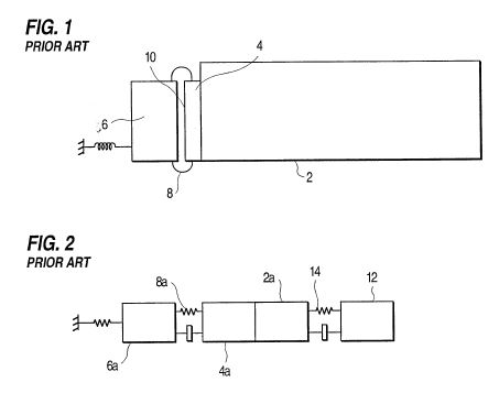
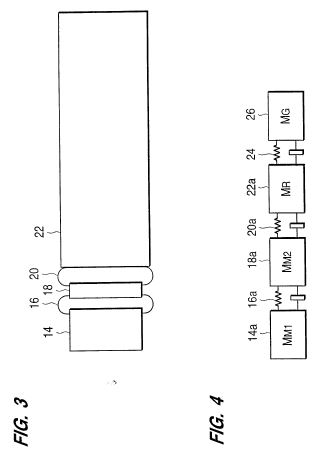
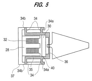
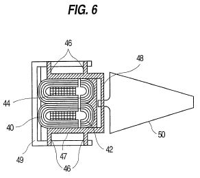

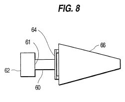
DETAILED DESCRIPTION OF PREFERRED EMBODIMENTS
FIG. 3 illustrates an embodiment of the present invention where a power take off (PTO) spring 20 has been added to the prior art device of FIG. 1 between the moving motor mass 18 and resonator 22. In operation, an dynamic force of frequency f is created between motor mass 14 and motor mass 18 which causes motor masses 14 and 18 to oscillate at frequency f in reactive opposition to each other. The periodic displacement of motor mass 18 causes a dynamic force to be transmitted through spring 20 to resonator 22 which in turn causes a periodic displacement of resonator 22 at frequency f. If frequency f is equal to a standing wave mode frequency of the resonator which can be excited by the resonator's motion, then the periodic displacement of resonator 22 will transfer energy to that mode.
FIG. 4 provides a lumped element diagram of the embodiment of FIG. 3, comprising motor mass 14a, motor mass 18a, motor spring 16a, PTO spring 20a, resonator mass 22a, fluid spring 24 and fluid mass 26. When a mode of resonator 22 iq being driven, the phases between the displacements of all masses 14a, 18a, 22a, and 26 are determined by the respective mass values and by the respective stiffness and damping values of motor spring 16a, PTO spring 20a, and fluid spring 24.
Adjusting the stiffness of PTO spring 20a of FIG. 4 provides a means to tune the mechanical power factor seen by the motor (represented by masses 14a and 18a) as it delivers power to the resonator, thus reducing the motor force required for a given power delivery to the load.
PTO spring 20a also prevents rigid coupling of resonator mass 22a with motor mass 18a, thereby making possible designs which reduce the motor force required for a given power delivery to the load. Reducing the required motor force results in reducing energy losses resulting from the motor's transduction efficiency and thus improves the overall efficiency of the power delivery system.
Reducing the required motor force also reduces the required size of the motor, thus reducing the amount of motor materials required for a given power delivery to the load.
PTO spring 20a of FIG. 4 allows power factors approaching unity to be achieved without having to tune any of the mechanical resonances, associated with springs 16a and 20a, close the driven acoustic resonance. Thus, component displacements are minimized, noise is reduced, and excessive spring stresses are avoided. Providing high power factors, without the risk of crossing acoustical and mechanical resonance frequencies, eliminates the severe control problems which occur due to resonance repulsion phenomena.
The stiffness of each mechanical spring can be chosen so that (i) the mechanical resonance frequency where motor spring 20a sees its maximum displacement is above the acoustic resonance frequency and (ii) the mechanical resonance frequency where spring 16a sees its maximum displacement is below the acoustic resonance frequency.
This design provides two preferred operating characteristics. First, fluid heating may cause the acoustic resonance frequency to increase during operation and this design assures that the acoustic resonance frequency will not cross the mechanical resonance frequency associated with the maximum displacement of spring 16a. Second, provided that the mechanical resonance frequency associated with the maximum displacement of spring 20a is sufficiently above the acoustic resonance frequency so that the two resonances never overlap during operation, then some benefit can be derived. As the acoustic resonance frequency increases, accelerations can also be made to increase thereby transferring more power to the load for the same motor force. Proper selection of component mass and spring stiffness can also cause the power factor measured at the air gap to improve as the acoustic resonance frequency increases.
In general, the addition of PTO spring 20a allows greater system design flexibility, since the properties of each mechanical element are more independent. PTO spring 20a allows tuning of all the relative component displacements, relative displacement phases, and component masses.
The power delivery unit should be resiliently mounted to ground, since each component of the system oscillates.
For a given design, the specific acceleration of masses depends on the mass of each component and stiffness and damping of each spring. The mass with the lowest acceleration provides a good point for resilient mounting to ground.
FIG. 5 shows a cross sectional view of a variable reluctance motor used as a two-mass dynamic force motor in accordance with the present invention. The variable reluctance motor consists of a first motor mass 28 formed by a stack of flat"E"laminations rigidly joined together so that the stack forms a single unit, a second motor mass 30 formed by a stack of flat"I"laminations rigidly joined together so that the stack forms a single unit, a conducting coil 32 wound around the center leg of the E lamination stack, leaf springs 34, with levels 34a and 34b, which resiliently join the first and second motor masses 28 and 30 together via carriages 35 and 37, and a PTO leaf spring 36 which resiliently connects the second motor mass 30 to resonator 38. Second motor mass 30 is rigidly connected to carriage 35, and first motor mass 28 is rigidly connected to carriage 37. Carriages 35 and 37 slide back and forth relative to one another.
The motor laminations can be constructed of silicon steel laminations which are typically used in transformers.
The mass of carriage 35 may be considered to be part of the second moving mass, and the mass of carriage 37 may be considered to be part of the first moving mass. The space between the three legs of the E laminations and the
I laminations comprises an air gap 40. The two levels of leaf springs 34, levels 34a and 34b, allow planer relative motion of second motor mass 30 and first motor mass 28 so as to keep the instantaneous air gap 40 everywhere uniform. Single level springs or any other spring topology could also be used which provide planer motion of the components.
In operation, when an alternating current is established in coil 32 a time varying magnetic flux is created within air gap 40 which is accompanied by a static attractive force and a time varying attractive force between the first and second motor masses 28 and 30. Motor masses 28 and 30 respond to this time varying force by oscillating in reactive opposition to each other. Leaf springs 34 provide a bias force to prevent the attractive force from drawing motor masses 28 and 30 together while still allowing them to oscillate. The periodic oscillation of motor mass 30 applies a dynamic force through PTO spring 36 to resonator 38, thus causing resonator 38 to oscillate along its cylindrical axis. If the oscillation frequency of resonator 38 is equal to one of the standing wave mode frequencies which can be excited by the resonator's motion, then the periodic displacement of resonator 22 will transfer energy into that mode. Variable reluctance motors provide high energy efficiency when small displacements and large forces are required, which is typically the case for acoustic resonators.
FIG. 6 shows a variable reluctance motor used as a two-mass dynamic force motor in accordance with the present invention, which reduces the portion of total magnetic losses caused by non-grain oriented magnetic flux. The variable reluctance motor consists of a first motor mass 40 formed by tape-wound laminations and joined to each other so as to form a single unit, a second motor mass 42 formed by tape-wound laminations and joined to each other so as to form a single unit, a conducting coil 44 wound around the center leg of the first motor mass, leaf springs 46 which resiliently join the first and second motor masses 40 and 42 together via carriages 47 and 49, and a PTO leaf spring 48 which resiliently connects the second motor mass 42 to resonator 50. The mass of carriage 47 may be considered to be part of the second moving mass, and the mass of carriage 49 may be considered to be part of the first moving mass. In operation the motor of FIG. 6 operates in the same manner as the motor of FIG. 5.
FIG. 7 illustrates an alternative magnetic structure for a variable-reluctance motor having first motor mass 52 formed of two tape-wound laminations and a second motor mass 54 formed of a single tape-wound lamination.
While second motor mass 54 does not prevent cross-grain field orientation, it does provide a simple and very rigid structure having ends 56 and 58 which provide convenient connection points for springs, carriages or other hardware. Many combinations of tape-wound and stacked flat lamination components can be combined based on given design requirements and will suggest themselves to those skilled in the art.
The PTO spring of the present invention can be used in combination with any type of dynamic force motor. All motors may be thought of as providing a dynamic force to a member causing some movement in that member, however small. Thus, all the motors, including all motors described herein are dynamic force motors.
Fig. 8 describes another type of dynamic force motor.
Fig. 8 illustrates an embodiment of the present invention having a PTO spring 64 with one end connected to a flexing dynamic force motor 60 and the other end connected to a resonator 66. Reaction mass 62 is preferably rigidly connected to flexing dynamic motor 60 at an end 61 thereof. Reaction mass 62 may be also be resiliently connected to flexing dynamic motor 60 at end 61, and in this case it is preferred that the resilient connection be relatively stiff compared to the spring constant or stiffness of PTO spring 64. Flexing dynamic motor 60 can be a piezoelectric element, a magnetostrictive element, or any other element which provides a dynamic force by periodically flexing or changing its overall dimensions.
In operation motor 60 of FIG. 8 undergoes a periodic change in its dimension thus creating a dynamic force of frequency f which is communicated to resonator 66 through PTO spring 64. In embodiments in which the dynamic force motor 60 has a small mass relative to that of the reaction mass 62, the force of the motor 60 is effectively transferred to the resonator 66 by virtue of the reaction mass 62 and PTO spring 64 which causes the periodic displacement of resonator 66 at frequency f.
Reaction mass 62 prevents excessive accelerations of the reaction mass end 61 of motor 60 and maximizes the force of motor 60 applied to PTO spring 64. If the frequency f is equal to a standing wave mode frequency of the resonator which can be excited by the resonator's motion, then the periodic displacement of resonator 66 will transfer energy into that mode. The embodiment of FIG. 8 can be operated without PTO spring 64 by rigidly connecting motor 60 to resonator 66. However, this would eliminate the advantages described above.
It may be seen that the embodiments of the invention utilize the PTO spring as the exclusive mechanism to couple the active force components of the motor to the resonator. Thus, the moving elements of the motor which are effective in causing oscillation of the resonator are isolated from the resonator by the resilient coupling mechanism, i. e., the PTO spring. In contrast, prior art devices couple the motor to the resonator by a rigid connection and do not utilize a PTO spring as the primary force path from the motor to the resonator.
While the above description contains many embodiments of the invention, these should not be construed as limitations on the scope of the invention, but rather as an exemplification of preferred embodiments thereof.
Other embodiments which will occur to those skilled in the art are within the scope of the present invention.
For example, any motor which generates a dynamic force can be employed such as off-concentric rotational motors, electrodynamic motors, and electromagnetic motors.
Variable reluctance motors need not use only laminations but can be formed from pressed materials that have multidirectional grain properties so as to avoid off-axis grain magnetic losses. The springs may comprise any spring type which accommodates a particular design such as coil springs, leaf springs, bellville springs, magnetic springs, gas springs or other devices that provide a resilient coupling. The fluids within the resonators of the present invention can be either liquids or gases. Any type of acoustic resonator can be used including cylindrical resonators or Resonant Macrosonic Synthesis (RMS) resonators of any shape as described for example in U. S. patents 5,515,684,5,319,938, and 5,174,130 the entire contents of which are hereby incorporated by reference.
It should further be appreciated that an excited resonance mode of the resonator may generally take place anywhere on the resonance response curve as, for example, at full or near full power, at half power points, quarter power points or the like. Thus a resonant mode can be excited over a range of frequencies.
The scope of the present invention is not limited to particular applications of the acoustic resonator to which power is delivered. For example the present invention can be applied to acoustic resonators for oilless acoustic compressors and pumps for air compression, refrigeration, comfort air-conditioning, hazardous fluids, ultra-pure fluids, natural gas, and commercial gases; acoustic resonators for process control ; acoustic resonators used as process reactors for chemical and pharmaceutical industries ; acoustic resonators for separation of gases including pressure swing adsorption ; and acoustic resonators for agglomeration, levitation, mixing, and pulverization to name a few. Such applications may or may not include RMS resonators.
While omitted for clarity, such applications of the invention may utilize inlet/outlet valves and heat exchange apparatus as shown in Figure 13 of patent 5,319,938 and Figure 16 of patent 5,515,684.
Accordingly, the scope of the invention should be determined not by the embodiments illustrated, but by the appended claims and their equivalents.
US6230420
RMS process tool
RMS process tool
Physical effects produced within RMS resonators are utilized as a means to process materials within the resonator including for example one or more of comminution, converting liquids into vapors and gases, drying of powders, rapid mixing of gases and various materials, agglomeration, de-agglomeration, granulation, chemical reactions, stratification/separation, and the destruction of biological material.
BACKGROUND OF THE CURRENT INVENTION
1) Field of Invention
This invention relates to the application of Resonant Macrosonic Synthesis (RMS) for the purposes of processing materials within an RMS resonator including, for example, comminution, converting liquids into vapors and gases, drying of powders, mixing of dissimilar materials, agglomeration, de-agglomeration, granulation, sterilization of gases, destruction of biological materials, separation by stratification, and coal gasification.
2) Description of Related Area
Previously, the processing of materials such as comminution, converting liquids into vapors and gases, drying of powders, rapid mixing of gases and various materials including mixtures of particulate solids, agglomeration, de-agglomeration, and granulation required a wide range of different processing equipment. Examples of such equipment can include rotary cutters, hammers, rollers, fluid-energy mills, ovens, and various filtration machines.
If the manufacture of a product requires more than one of these processes, then the product will often be progressively transferred from one machine to another. This can create disadvantages, due to reduced yield, product contamination, longer process time, and high production costs and worker exposure to processing agents.
A single process tool that can provide multiple process steps without product transfer and in a simpler manner would provide a significant advantage to the process industry.
SUMMARY OF THE INVENTION
It is the object of an embodiment of the present invention to utilize the physical effects produced within RMS resonators as a means to process materials within the resonator including for example one or more of comminution, converting liquids into vapors and gases, drying of powders, rapid mixing of gases and various materials, agglomeration, de-agglomeration, granulation, chemical reactions, stratification/separation, and the destruction of biological material.
A further object of an embodiment of the invention is to provide a method for processing materials in a self-contained, scaled tool for batch.
A still further object is to provide a process tool capable of generating a broad range of physical effects, such that multiple process steps can be performed within a self-contained, sealed tool, which may include simultaneous and sequenced process in a batch and/or continuous manner.
Yet another object of an embodiment of the invention is to apply an RMS acoustic process tool to process materials.
The RMS acoustic process tool (APT) of the present invention consists of an RMS system including an acoustic resonator capable of producing: an extremely large range of dynamic pressures, both pumping and levitation via nonlinearly-generated DC pressures, high acoustic particle velocities, streaming velocities, and turbulence. The APT also includes an entire-resonator drive system capable of providing the power necessary to produce these effects.
The shape of the APTs resonator is chosen to promote the specific effect(s) listed above, which will provide the desired process or processes. Inside the resonator is a fluid that serves as the medium within which an acoustic standing wave is created. The fluid can consist of a liquid, a gas, a vapor, a vapor-gas mixture, a liquid or particulate aerosol, or a mixture of any number of the forgoing fluids. The method of operation is such that as the actuator oscillates the entire resonator at the frequency of one of its acoustic modes, a standing acoustic wave is produced.
One of the advantages of the APT is the number of different process that can be performed within the same tool during a single processing session. Materials within the resonator are exposed to physical effects, such as high dynamic pressures, levitation via nonlinearly-generated DC pressures, acoustic particle velocities, streaming velocities, and turbulence. The relative magnitude of these effects is determined by the resonator's shape and the power delivered Depending upon the materials introduced into the resonator, these physical effects promote various types of processing including one or more of: the size reduction of solid matter (comminution), agglomeration, de-agglomeration, granulation, the vaporization/atomization of liquids, the drying of powders, the nixing of dissimilar materials such as gases, vapors, and powders, destruction of biological material, and chemical reactions.
The rate at which these processes occur can be controlled by varying the power delivered to resonator. Many of these individual process can be combined to occur concurrently or in a desired sequence within a single APT by varying the input power level.
Another advantage of the APT is that the high kinetic energy required for certain processes such as rapid mixing, rapid de-agglomeration, and communition are created within the resonator via the stored energy of the standing wave. This internal energy source eliminates the need for external energy sources that are outside of the tool, such as external pumps or compressors.
These and other objects and advantages of the invention will become apparent from the accompanying drawings, wherein like reference numerals refer to like parts throughout.
BRIEF DISCRIPTION OF THE DRAWINGS
FIG. 1 is a sectional view of an acoustic process tool (APT) in accordance with the present invention;
FIG. 2 is a partially sectional view of a batch operation as applied to the de-agglomerating of a pharmaceutical cake inside of a blister.
FIG. 3 is a sectional view of an APT in accordance with the present invention that provides various targets for improving process results and various inlet and outlet tubes for either batch or continuous operation;
FIG. 4 is a graphical representation of the DC pressure distribution within the APT of FIG. 3,
FIG. 5 shows an alternate piston arrangement for driving the resonator.
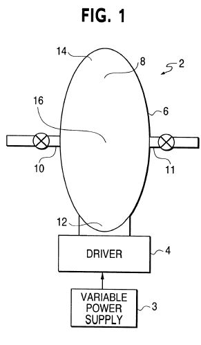
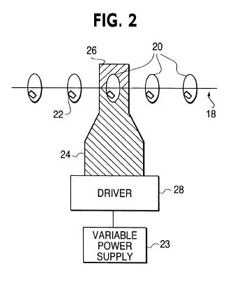
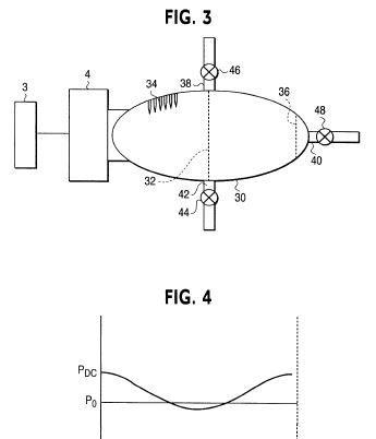

DETAILED DESCRIPTION OF THE PREFERRED EMBODIMENTS
FIG. 1 illustrates an acoustic process tool (APT) 2 having driver 4 and resonator 6 being constructed so as to provide a sealed (air-tight) chamber and being filled with a fluid. Materials to be processed are placed in the interior 8 of resonator 6. The material to be processed can be added to resonator 6 in many ways as for example through conduit 10, which can be located anywhere on the process tool 2. In general, the internal geometrical shape of resonator 6 will determine the pressure and velocity distributions and waveforms within interior 8 as described in U.S. Pat. No. 5,515,684 incorporated herein by reference. Entire resonator driving, as illustrated in FIG. 1, is described in U.S. Pat. No. 5,515,684, U.S. Pat. No. 5,319,938, and U.S. patent application Ser. No. 08/979,931 now U.S. Pat. No. 5,994,854, the entire contents of which are all hereby incorporated by reference. FIG. 5 is derived from FIG. 15B of U.S. Pat. No. 5,515,684, and illustrates an alternate driving mechanism for the RMS resonator 74 using piston or diaphragm 80' and electromagnetic driver 94'. The scope of the present invention is not limited to the shape of resonator 6 in FIG. 1, but instead can have an infinite variety of shapes. The specific resonator shape and its resulting characteristics will be chosen by the designer to fulfill the requirements of a particular application.
In operation driver 4 oscillates resonator 6 at the frequency of an acoustic standing wave mode thereby creating a standing acoustic wave within resonator 6. The driver is supplied with a variable power supply 3 to permit control of the acoustic energy within the chamber. In this way standing waves with extremely high energy densities can be generated, which provide a range of physical effects employed by the present invention. The physical effects produced include one or more of high dynamic pressures, high ambient temperatures, high dynamic temperatures, levitation via nonlinearly-generated DC pressures, high acoustic particle velocities, high streaming velocities, and turbulent flow volumes of high scale that can fill a substantial portion of the resonator's internal volume. U.S. Pat. No. 5,515,684 teaches that excessive turbulence can increase the energy dissipation within a resonator and also teaches methods to minimize the turbulence. For certain RMS applications, such as acoustic compressors, energy efficiency can be increased by minimizing turbulence. In contrast, many of the processes of the present invention are enhanced by the turbulence that is easily created by the high acoustic velocities that RMS resonators can provide.
RMS resonators generate the high energy densities and physical effects required for APT's to function and enable the new processing approaches that ATP's provide. These physical effects and their application to particular processes are described as follows.
1) Comminution
Acoustic comminution is facilitated by high amplitude standing waves that produce high acoustic velocities, high streaming velocities, turbulent flow, and levitation.
The acoustic standing wave exists in the host gas that fills resonator 6. The host gas can be air or any number of other gases and will be at a pressure that is appropriate for a given process. Assuming for example that the first longitudinal mode of resonator 6 is excited, then the host gas within the resonator will oscillate back and forth along the resonator's cylindrical axis, changing direction twice during a single acoustic cycle. In RMS resonators, these oscillating axial velocities can approach and potentially exceed the quiet condition sound speed (MACH 1) in that gas.
Other flows within the gas that exert forces on the process particles are nonlinearly-driven streaming velocities and turbulent flow. At high acoustic amplitudes streaming flow loops are generated between pressure nodes and anti-nodes and are also created by the particles themselves. The streaming velocities created by the particles can exceed the node-to-antinode streaming velocities. Also, at high amplitudes the oscillating axial flow transitions from laminar flow to turbulent flow.
Another effect due to the presence of the high amplitude acoustic wave within resonator 6 is the nonlinearly driven, so called, "DC pressure." As known to those skilled in the art, the DC pressure varies along the axis of the resonator forming a static pressure gradient. This static gradient can levitate objects within the resonator. The shape and symmetry of resonator 6 will result in a DC pressure distribution having a maxima at ends 12 and 14 and a minima at the half-length point 16. FIG. 4 illustrates the type of static pressure distribution that would be expected within resonator 6. This DC pressure gradient will tend to push the process particles away from ends 12 and 14 and towards the center of resonator 6.
When the particles to be comminuted are placed within resonator 6 of FIG. 1 they are typically subjected to all of the forces described above. Levitation tends to push the process particles away from ends 12 and 14 and keeps them where oscillating axial flow, turbulent flow, and streaming flows are high The oscillating axial flow will exert a force on the process particles that will tend to move them in the direction of the instantaneous axial flow. As the particle is accelerated back and forth in response to these oscillating axial forces it is also propelled through the turbulent flows and streaming flows. The particle itself also creates streaming flows that in turn create further unbalanced forces that will accelerate the particle.
Consequently, the process particles experience collisions with the walls of resonator 6 and with each other. RMS resonators can provided energies high enough such that these particle-wall and particle-particle collisions will break the process particles into smaller pieces, and thereby provide comminution. The present invention has been used to comminute materials such as whole coffee beans, salt, sugar, and other materials. Micron and sub-micron (i.e. nano-phase) sizes can be achieved.
The actual velocities achieved by the process particles will vary inversely with particle size. When particles are first introduced within resonator 6, their oscillating axial displacement will typically be a fraction of the host gas' displacement.
It is the nature of an APT that nearly all of the resonator's interior volume can be substantially filled with high velocity flow so that process particles are almost continually undergoing comminution. In this way the results of the process are enhanced and rapid efficient comminution is provided.
The APT comminution process can be employed in many processes such as the comminution of pharmaceutical agents, manufacture of printer toner, gasification of coal, recovery of precious metals from stone and other geological specimens, and plastics recycling.
2) Destruction of biological materials
The extremely high dynamic, pressures, dynamic temperatures, axial and turbulent velocities generated within an RMS resonator can be used to sterilize air and other gases by destroying bacteria and viruses via exposure to high temperatures and through high energy impacts as previously described for comminution.
3) Agglomeration and de-agglomeration
As acoustic amplitudes are increased from very low levels, the different physical effects previously described will vary in magnitude. At amplitudes low enough to avoid substantial turbulence, the combined effects of levitation and acoustically generated flows will lead to agglomeration of particulate process materials. Applications for agglomeration include pollution abatement through the removal of ash and other combustion products from air. Also, by injecting a granulation-promoting substance (a "binder" as it is commonly called) inside of resonator 6 of FIG. 1, granulation can be accomplished inside the APT.
When the acoustic amplitudes are increased beyond the agglomeration level the agglomerated materials within resonator 6 of FIG. 1 will be de-agglomerated in the same manner and according to the same principles as described above for comminution. If so desired, low amplitude agglomeration inside the APT can be avoided by starting the process at energy levels high enough for de-agglomeration. For many applications, de-agglomeration involves the breaking of weak bonds between preexisting particles which were formed prior to the de-agglomeration process. As such, the acoustic amplitudes required for de-agglomeration will be less than those required for comminution. This will be the case for applications such as pharmaceutical processing where care must be taken not to alter the de-agglomerated particle size nor to alter the properties of the process materials with excessive temperatures and pressures. The APT can be adjusted to run at the energy level appropriate for a given application by reducing the drive power to the motor.
De-agglomeration applications are found for example in the pharmaceutical industry both for continuous and batch operations. One particular manufacturing process results in an agglomerated cake inside of a sealed blister as shown in FIG. 2. The cake must be de-agglomerated into a powder to place the product in its intended form for use. In FIG. 2 a pharmaceutical blister pack or strip 18 includes a series of blisters 20 with each blister 20 containing an agglomerated cake 22. In this embodiment of the present invention, each blister 20 is supported on blister strip 18 and serves as the resonator. Each blister 20 is filled with an appropriate gas and has a shape that is designed to provide acoustic de-agglomeration as previously described. A blister volume is typically less than 1 cc and contains an agglomerated cake of even smaller volume. Entire resonator drive is employed via ultrasonic horn 24, which is driven by ultrasonic driver 28 connected to variable power supply 23. Axial displacements of the horn are small enough to allow the blisters to remain connected to the blister strip during resonant driving. Many other types of drivers can also be used Horn 24 is temporarily but rigidly joined to horn cap 26 during resonant driving. Ultrasonic horn 24 and horn cap 26 are shown in cross section and provide a means to oscillate the entire blister 20 along its cylindrical axis at the desired resonance frequency and also provide extra rigidity to blister 20 if needed.
To minimize electronic controls the ultrasonic horn can be swept through the blister's resonance frequency once or multiple times to excite the acoustic mode and de-agglomerate the cake. The sweep rate would be adjusted so as to allow the acoustic amplitude within blister 20 to reach the appropriate level for de-agglomeration. This process can be automated into steps so that horn 24 and horn cap 26 separate and retract after de-agglomeration of a blister, the sheet of blisters is advanced and horn 24 and horn cap 26 reengage the next blister. Many transducers can be operated in parallel at once to increase the yield of the same process.
4) Reduction of liquid-to-vapor and liquid-to-gas
The process of vaporizing liquids is accomplished, within resonator 6 of FIG. 1, in the same manner and according to the same principles as described above for comminution. RMS resonators can provide enough energy not only to vaporize liquids into droplets but to further reduce droplets to the gas phase. As in the case of de-agglomeration, care must be taken to use the energy required to provide the desired result, whether it be a vapor, a gas, or disassociated molecules The APT can be adjusted to run at the energy level appropriate for a given application by reducing the drive power to the motor.
Typical applications can include vaporization of fuels for combustion processes and combustion engines; vaporization of liquids for chemical, pharmaceutical, food and beverage, materials science, and electronic device manufacturing; and vaporization for respiratory drug delivery, where liquid and solid particulate aerosols must be created.
5) Mixing of various process materials
The process of mixing various materials, such as liquid vapors, gases, and powders is accomplished, within resonator 6 of FIG. 1, in the same manner and according to the same principles as described above for comminution. APTs can rapidly generate high-density aerosols. The complex flow field created by the superposition of the oscillating axial flow, the turbulent flow, and the streaming flows can provide extremely rapid mixing of various materials. For each particular combination of process materials, care should be taken to use energy levels that will not alter the desired properties of the materials.
Typical applications include rapid gas mixing for chemical and pharmaceutical applications, rapid fuel-air mixing for combustion engines and other combustion processes, and mixing of gases and nanophase particles for film depositions, and electronic device manufacturing processes.
6) Drying
The physical effects previously described for comminution will accelerate the drying of process materials. A drying process within a APT may require a flow of dry and/or heated gas through the tool. In FIG. 1, a superimposed dry gas flow can be provided by pumping the dry gas into resonator 6 via tube 10 and allowing the used gas to exit resonator 6 through tube 11. The application of microwaves provides another means of applying heat to the process materials during processing, wherein the resonator can act as a microwave cavity. While RMS resonators provide the advantage of a sealed system, they can also operate when opened to the external environment as required by the presence of tubes 10 and 11. The tubes can be provided with appropriate filters to prevent any loss of the process materials.
7) Abrasion or "sand blasting"
Abrasive particulates can be used within the APT to "sand blast" a solid object rigidly fixed within the resonator. Repeated high velocity impacts of such abrasive particulates with the surface of the solid object will result in the abrasion of the object's surface. In this way, highly complex shapes may be processed so as to, for example, clean the object of scale, paint, rust, oxides, and other undesired surface coatings without exposure of human operators to dust and particulates resulting from the abrasion process.
8) Chemical processes
The process tool of the present invention can also be used to drive chemical reactions. RMS resonators can provide extremely high dynamic pressures, dynamic temperatures, and kinetic energies for use in enhancing chemical reactions.
For example, the process time required for thermally-driven chemical reactions will normally include time for heating and cooling the reactor. Thermally-driven chemical reactions can be controlled in a new way in the APT. The high dynamic temperatures generated within a RMS resonator can be used to turn a chemical reaction off and on at the acoustic frequency. By varying the input power to the resonator the dynamic temperature amplitude can be varied, which in turn will change the fraction of the acoustic cycle during which the reaction temperature requirement (high or low) is met. Thus, by varying the power input to the resonator, a nearly instantaneous control over the rate of reaction would be provided.
High kinetic energies achieved within an RMS resonator can be used to accelerate catalytic reactions, when a catalyst is placed within the resonator. A catalyst can be added to the material to be processed, formed on the resonator wall, or added as sheets or plates oriented in the direction of the oscillating axial flow.
When filled with a liquid, the APT has the flexibility to provide cavitation for sono-chemical reactions at ultrasonic frequencies or well below the ultrasonic range. In sono-chemistry systems that use ultrasonic sources, it is much more difficult to create uniform cavitation throughout the reactor's volume and to transfer the power needed for commercial practicality. The APT provides a means to fill a very large volume of the reactor (i.e. resonator) with cavitation and to do so at very high power levels.
Other chemical reactions and process steps that may be achieved within an APT include oxidation, reduction, metal coating, metal scrubbingor ablation, dissolution of solids into liquids, crystallization, polymerization, de-polymerization, separation processes such as high-speed pressure swing adsorption, sparging (aeration/deaeration), gas/liquid reactions (chlorination), and VOC abatement. The application of microwaves provides another means of applying heat, or a more complex interaction, during a chemical process, wherein the resonator can act as a microwave cavity.
The batch and continuous methods described previously can also be used for chemical reactions within the APT. Chemical reactions can be combined with many of the previously described processing steps inside the same APT. In short, the APT provides a single tool, or reactor, with which the process engineer can design a wide range of processes that may have previously required multiple tools or reactors.
8) Separation
Stratification by particulate size along the axis of a resonator is well known in the field of acoustics. An APT provides a practical means for delivering large amounts of power and greatly increasing the yield of an acoustic stratification process. This particular use of an APT can be applied to the separation of gases.
9) Enhancing processing results
The degree of axial, streaming, and turbulent velocities can be changed by altering the internal surface finish and internal geometry of the APT's resonator. As described in U.S. Pat. No. 5,515,684 the peak axial velocities achieved, for a given pressure amplitude, will depend on the resonator's overall shape. Once a given shape is chosen, local streaming and turbulent velocities can be altered by changing the internal surface finish, or roughness, and by inserting targets in the flow stream. Increasing the turbulent and streaming velocities can increase the processing rate for applications such as mixing, de-agglomeration, drying, vaporization, and comminution, and thus can provide a significant advantage.
FIG. 3 shows example embodiments of targets that can be used to increase yield where a resonator 30 has a screen 32 which spans the internal volume of resonator 30 in a direction transverse to the axial acoustic velocities. The mesh size of screen 32 can be chosen so as not to overly impede the axial flow, but to promote the early development of turbulence during a given acoustic cycle. In this way, both the turbulent duty-cycle, with respect to an acoustic cycle, and the turbulent intensity can be increased, thereby providing more processing during a single acoustic cycle. Multiple transverse screens can be added to further accentuate the effect. Surface protrusions 34 provide another style of target to increase processing performance, by promoting turbulence. The resonator 20 is driven by driver 4 and connected to variable power supply 3 as shown in FIG. 1.
The targets described have a two-fold effect First they will increase the rate of particle-particle collisions as well as their impact velocities and second they can provide increased surface area for particle-resonator collisions.
Many other geometrical arrangements to promote turbulence will suggest themselves to those skilled in the art and are considered to be within the scope of the present invention. It is also understood that the addition of targets is a matter of increasing yield and efficiency and that a RMS resonator can provide the processing features of the present invention without targets.
In general, the location, size, geometry, and quantity of these targets, or obstructions, can be modified to optimize the process as desired. Other approaches can be used to increase the processing rate and to alter the processing characteristics such as the particle size distribution for comminution. For example, passive media, such as beads of various materials, can be placed within the resonator to optimize comminution, mixing, and de-agglomeration. Such enhancements are not limited to a batch mode system, but can also be applied to a continuous mode system described herein.
The APT of FIG. 3 provides outlet tubes 40 and 42 as a means to remove processed materials from the tool. For batch operations, resonator 30 can be fitted with flanges for direct opening of the resonator in order to add and remove process materials. Alteratively, materials can be placed within resonator 30 through inlet tube 38 and valve 46 and can be removed through either outlet tube 42 and valve 44 or through outlet tube 40 and valve 48. During processing, valves 44, 46 and 48 can be closed to provide a sealed processing environment. Removal of processed materials through outlet tube 42 can be assisted by "swept air cleaning" consisting of an external pressure source connected to inlet tube 38 which would create flow through tube 38, into resonator 30, and out through tube 42. In this way the processed materials would be entrained in the flow and carried out of resonator 30.
Another means for discharging the processed materials is to use the nonlinearly generated DC pressure created by the standing acoustic wave inside the resonator. The graph of FIG. 4 illustrates the type of DC pressure distribution that would be expected within resonator 30. Po represents the at-rest pressure within resonator 30 when no standing wave is present. The curve PDC shows how the local at-rest pressure PO is altered in the presence of a high amplitude standing wave. Unlike the at-rest pressure PO the altered static pressure PDC is high at the resonator's ends and lowest at the center of the resonator.
If valves 46 and 48 are opened at the same time, then the DC pressure will discharge gas through tube 40 and draw gas in through tube 38. The resulting flow will entrain the processed materials and discharge them from resonator 30, thus eliminating the need for an external pressure source for sweeping the resonator. Any RMS resonator can provide DC pressure and need not have the specific shape shown in FIG. 3. The placement of inlet tube 38 and outlet tube 40 provides the greatest DC pumping pressure, as illustrated in FIG. 4. However, DC pressure pumping can occur with inlets and outlets being located anywhere along the length of resonator as long as there is a DC pressure difference between the inlet and outlet positions. Multiple inlets and outlets can be used to increase material flow and another outlet tube similar to tube 40 could be located at the other end of resonator 30.
10) Continuous process
In addition to batch processing, the APT of FIG. 3 can also operate in a continuous process mode. An external pressure source can continuously deliver move process materials through tube 38, into resonator 30, and out through tube 42. Process materials can also be continuously delivered by allowing the DC pressure to move them through tube 38, into resonator 30 where processing occurs, and out through tube 40. For both nthe externally-driven and DC pressure-driven versions, the flow rate of the gas through the chamber 32 can be controlled with the respective valves independently from the acoustic processing.
For continuous comminution processes, a classification screen 36 can be added to the APT of FIG. 3 having a mesh size so as to prevent particles from leaving the resonator until they have been reduced to the desired size. By locating classification screen 36 inside resonator 30, a self-cleaning action is provided by the oscillating acoustic flow and pressure, thus preventing clogging of the screen.
Additional parallel layers of classifying screens can be located along the cylindrical axis of resonator 30 having progressively smaller mesh sizes from inlet to outlet. In this way, large initial particles will not have to travel far along the resonator's axis before impacting a screen through which it cannot pass until the particle is broken down to a smaller size. Once reduced in size, it will experience greater axial accelerations and displacements allowing it to hit the next smaller mesh size screen. The process continues until the particle can pass through the last screen mesh.
It is particularly advantageous to use an APT in continuous mode for processes such as therapeutic aerosol generation. Aerosol generators or "nebullizers" used for therapeutic purposes often utilize high velocity air strews to impart the energy needed to create aerosols from liquids. A distribution of droplet sizes is thereby created, only a fraction of which are the correct size for inhalation. In addition, the high velocity air streams required are generally of sufficiently high volumetric flow as to require deceleration by externally placed baffles prior to delivery to a patient. Because the energy needed to break a liquid into droplets is acoustically supplied in an APT, it is possible by varying the geometry of the chamber to independently regulate the air flow through the resonator at a level required for human inhalation and to optimize the air flow velocity so as to entrain only droplets of therapeutic size.
11) Process Control
Every degree of each physical effect created within an RMS resonator can be continuously varied by varying the input power to the motor driving the resonator. Also, a transition can be made from one physical effect to another by varying the power input, as in the case of switching from agglomeration to de-agglomeration and from stratification to mixing. Acoustic stratification of particles by size occurs at lower acoustic amplitudes.
Controls can be provided to select the desired process and adjust its rate by varying power input to the motor. Information regarding percent completion of a given process can be inferred by measured parameters such as power consumption at a reference acoustic pressure amplitude and change in resonant frequency. For example, at a given dynamic pressure amplitude a batch comminution process may require less power as particle sizes are reduced. The periodic addition or discharge of process materials, gases, liquids, vapors, powders and reactants can be automated by those skilled in the art of process control and electromechanical design.
There are many ways to exploit the new features of the present invention that will readily occur to one skilled in the art of process engineering. One of the principal advantages of the APT is provided by the wide range of physical effects that can be generated within a single chamber. As such, there are innumerable ways to combine simultaneous and sequenced processes within a single APT, thereby unifying and simplifying formerly complex processes. For example, a process requiring comminution of solids, mixing the comminuted product with gases and other powders, vaporization of liquid reactants, controlling a chemical reaction, agglomeration, and discharge of the final product can all be performed within a single APT by simply supplying the proper materials and controlling the power input to provide the respective physical effects. The number of other combinations of parallel and sequenced processes that can be realized with an APT is virtually endless but is in fact made possible by the unique features of the present invention. Thus, the performance of multiple complex processes within a single APT is considered to be within the scope of the present invention.
As with any process tool, APTs of varying sizes and designs can be placed in series and used to process materials in stages.
An APT requires no specific physical orientation to create the desired physical effects, and so the designer is free to orient the APT in any manner that facilitates a particular design requirement, such as a gravity feed of process materials or loading and unloading process materials, or controlled entrainment of liquid droplets or solid particulates by a gas flowing through the unit. A resonator can be removed from its driver and used to transport the pressed materials in order to avoid contamination. An APT can be operated at extreme temperatures if required by a particular process and can be heated or cooled with conventional methods, Construction materials can be chosen as appropriate for compatibility with given process materials. The number of resonator shapes that will provide the physical effects described herein is unlimited and the specific shape chosen for a given APT design will reflect the given process or processes of interest.
Resonator size should not be considered as a limitation on the scope of the invention, since resonators can be scaled to extremely small sizes (e.g. micromachines) and to very large sizes capable of delivering thousands of watts of processing power.
Further, modes of operation can involve using a fluidized bed approach to prevent the process materials from becoming acoustically opaque, thereby maximizing the volume of materials that can be loaded into a single resonator, while still being able to excite the standing wave mode.
APT resonators have no mechanical frictional moving parts and so provide great flexibility in materials selection Resonators can be constructed from materials that provide long-life, non-contamination, and non-reactivity such as stainless steel, monel, hastalloy, glass, ceramic or plastic.
Monitoring of APT processes can also be provided by means of transparent windows in the resonator. Windows can be used for noninvasive optical measurements to determine the degree of process completion.
ABSTRACTS
EP0447134
Standing wave compressor.
EP0447134
Standing wave compressor.
A compressor for vapor-compression cooling systems, which exploits the properties of acoustic resonance in fluids for fluid compression, and provides a discharge pressure which can be varied during operation in response to changing operating conditions, thereby providing an oil-less compressor and reducing the compressor's energy consumption. The thermoacoustic properties of standing acoustic waves are exploited to provide a refrigerant subcooling system which is contained within the compressor. Refrigerant subcooling occurs when heat exchange is provided between the refrigerant and a heat pumping surface, which is exposed to the standing acoustic wave within the compressor. Acoustic energy can be provided by either a mechanical driver, or by direct exposure of the fluid to microwave and infrared energy, including solar energy. Inlets (4) and outlets (6) arranged along the chamber (2) provide for the intake and discharge of a fluid refrigerant, and can be provided with optional reed valve arrangements, so as to increase the compressor's compression ratio. The performance of the compressor can be optimised by a control circuit which holds the wavelength of the standing wave constant, by varying the driving frequency in response to changing operating conditions.
US6388417
High stability dynamic force motor
High stability dynamic force motor
Motor control of a variable reluctance motor is obtained by providing a periodic voltage waveform to a coil of a motor. No coil current control or current or flux feedback is needed to obtain flux waveforms that allow for low-distortion or distortion-free operation of the motor. The periodic voltage waveform may be a sinusoidal or sawtooth signal, for example, and has a substantially zero mean for each cycle of the signal. The periodic voltage waveform may be offset to compensate for the resistance of the coil, and the coil current may be monitored in order to determine the amount of offset required. By providing a zero-mean or substantially zero-mean periodic voltage waveform, the coil current and flux in the gap between the core and the moving part are guaranteed to reach a zero value at some point during each period (or cycle) of the periodic voltage waveform.
US5357757
Compression-evaporation cooling system having standing wave compressor
Compression-evaporation cooling system having standing wave compressor
A compressor for compression-evaporation cooling systems, which requires no moving parts. A gaseous refrigerant inside a chamber is acoustically compressed and conveyed by means of a standing acoustic wave which is set up in the gaseous refrigerant. This standing acoustic wave can be driven either by a transducer, or by direct exposure of the gas to microwave and infrared sources, including solar energy. Input and output ports arranged along the chamber provide for the intake and discharge of the gaseous refrigerant. These ports can be provided with optional valve arrangements, so as to increase the compressor's pressure differential. The performance of the compressor in either of its transducer or electromagnetically driven configurations, can be optimized by a controlling circuit. This controlling circuit holds the wavelength of the standing acoustical wave constant, by changing the driving frequency in response to varying operating conditions.
WO1998032216
Resonant macrosonic synthesis (rms) energy conversion
Resonant macrosonic synthesis (rms) energy conversion
An energy conversion device comprises an acoustic resonator (2), a pulse combustion device for creating a standing wave within said resonator, and an electric (16) alternator. The alternator (16) is coupled to the resonator (2) to convert acoustically driven mechanical vibrations into electrical power.
MX9601981
RESONANT MACROSONIC SYNTHESIS.
RESONANT MACROSONIC SYNTHESIS.
An acoustic resonator includes a chamber containing a fluid. The chamber has anharmonic resonant modes and provides boundary conditions which predetermine the harmonic phases and amplitudes needed to synthesize a non-sinusoidal, unshocked waveform.