
rexresearch.com
Previous ~ Next ( Tech Report )
Bogdan MAGLICH
Migma Fusion
British Patent Specification # 1,422,545
(Cl. G6P 3E4X) 28 January 1978
Nuclear Fusion Reactors
Bogdan Maglich
This invention relates to nuclear fusion reactors, and more particularly, but not exclusively, to a method and means for deriving electrical power from nuclear fusion produced by the self-colliding of the ions within a mixture of accelerated ions of like charge in a magnetic field.
In the field of nuclear energy and nuclear power generation, it is advantageous to use the nuclear process in which two ions (nuclei) collide and form, as a result of their interaction, new ions (nuclei), the sum of whose masses is smaller than the sum of the masses of the two original colliding ions, the mass difference being converted into the kinetic energy of the new ions (nuclei).
Various means have been proposed to this end comprising the systems described in the review: "Controlled Fusion Research and High Temperature Plasmas" published in Annual Review of Nuclear Science, vol 20 (970), p. 509, et seq. However, these and the other systems proposed or attempted heretofore are based on a plasma thermonuclear approach; that is, they employ various means to heat neutral and negative ions (nuclei, molecules and electrons) to a high enough kinetic temperature so that the ions gain sufficiently high velocities to overcome their electrostatic repulsion and thus undergo the fusion reaction by collision. None of the hitherto proposed devices associates self-trapping and self-colliding features; stable self-confinement for periods of seconds; automatic multiple traversal and high kinetic temperature of the order of over a thousand million degrees needed to produce a sufficient number of nuclear reactions for the net production of fusion energy; nor do they have, because of the relatively high plasma densities involved, the possibility for conversion of the fusion energy into electricity in a simple manner.
Historically, the idea of achieving nuclear fusion in colliding beams of positively charged ions is at least 20 years old. The rejection of the idea is very nearly as old. The main problem encountered has been that the Coulomb scattering removes particles from the reacting beam so much faster than fusion occurs that producing a net power output is hopeless.
Recently, however, several developments have occurred which make this old idea look very attractive. Firstly, the concept of self-colliding orbits was conceived in 1969 by R. Macek and B. Maglich and published in the paper "The Principle of Self-Colliding Orbits and its Possible Application to pi-pi and mu-mu Collisons", published in Particle Accelerators, vol. 1, p. 121-136 (1970). Secondly, it was realized that this concept, originally proposed for collisions of particles of opposite charges, makes possible mixing of positively charged particle beams and head-on collisions of the particles of the same charge in spite of the fact that they precess in the same direction. Thirdly, it was realized that this concept makes possible the construction of a device which produces automatic return to the reaction region of elastically scattered particles in one revolution, i.e., instantaneously, thus increasing the probability of self-collision between the particles. Fourthly, it was realized that the vertical and horizontal focusing in such a self-colliding device is capable of greatly reducing losses due to elastic scattering beyond the vertical and horizontal confinement angle, namely, that the effect of focusing on the scattering of ions with residual gas which was originally found in the accelerator studies and published e.g. by Fisher in "Residual gas scattering, beam intensity, and interaction rate in proton storage rings" CERN Report ISR-VAC 167-16, is also applicable to the scattering between accelerated ions in the organized mixture of ions. Fifthly, it was realized that by using deuterons and injecting them into the self-colliding device with a particular range of energies, a breeding effect can be achieved releasing significantly greater ion energy per fusion.
Finally, the first device for colliding beams of nuclei, the CERN Intersecting Storage Rings at Geneva, has provided supporting experimental information on the long-term stabilities of organized systems of colliding positively charged ions in contrast to the well-known instabilities problem with plasmas. In particular, it was found empirically, that the removal of the electrons from the colliding system by the use of clearing fields and ultra-high vacuum increases the stability of the colliding beams by a factor of 105 (see report by K. Johnson in Proceedings of the 8th International Conference on High-Energy Accelerators --- CERN 1971).
According to the present invention there is provided a fusion reactor comprising:
(a) means defining an evacuated volume having a central axis and a center plane normal thereto;
(b) means for producing a magnetic field within said volume which field decreases with the radial distance from the central axis and increases with the distance along the central axis from the center plane;
(c) means for injecting ions of like charge from the periphery into the vicinity of said magnetic field with induced vertical oscillation and with an initial rate of injection sufficient to produce fusion reactions by the collisions of the resultant orbitally precessing ions with each other.
According to the present invention there is also provided a method for controlled release of nuclear fusion power, comprising the steps of:
(a) producing a magnetic field within an evacuated reaction volume having a central axis and a center plane normal thereto, the strength of which field decreases with the radial distance from the central axis and increases with the distance along the central axis from the center plane so as to induce precession of. And exert radial and axial focusing forces on, orbiting ions within said volume; and
(b) injecting a beam of ions of like charge from the periphery into the vicinity of the center of symmetry of said magnetic field with induced vertical oscillation and with an initial rate of injection sufficient to produce fusion reactions by the collisions of the resultant orbitally precessing ions with each other.
According to the present invention there is also provided a fusion reactor comprising:
(a) means for defining an evacuated volume;
(b) a plurality of cell means within said volume, each having a central axis and a venter plane intersecting normally at a center of symmetry and means for producing a magnetic field therein which field decreases with the radial distance from the central axis and increases with the distance along the central axis from the center plane; and
(c) means for injecting ions of like charge into each of said cell means from the periphery into the vicinity of the center of symmetry of its magnetic field with induced vertical oscillation and with an initial rate of injection sufficient to produce fusion reactions by the collisions of the resultant orbitally precessing ions with each other;
(d) said cell means being arranged in a three-dimensional matrix with their central axes and center planes in substantial alignment.
Embodiment of the present invention include a magnetic field which decreases with the radial distance from its central axis and increases with the distance along the central axis from its center plane, so that injected accelerated ion beams are mixed in an organized manner in precessing orbits designed so as to make them collide head-on or nearly head-on in the central region of the device continuously and automatically; and ions that have not undergone fusion are continuously and automatically retuned by the field to the collision region, thus considerably increasing the collision probability through self-multiplication of collisions by such multiple traversals which may occur on the order of 108 per second.
The collision probability is further increased by accelerating (rather than by heating) the ions to an energy at which the reaction parameter (the product of the fusion cross-section and the relative ion velocity) is maximized. For example, in the preferred embodiment described below, deuterons are accelerated to an energy of 2.6 MeV which corresponds to a kinetic temperature of collision of over 10 thousand million degrees centigrade; at these temperatures, the reaction parameter for deuteron-deuteron fusion is about 104 times larger than at thermonuclear temperatures.
Additionally in embodiments of the present invention, the properties of the self-colliding orbits can be exploited to inject and confine the atomic nuclei without external means, namely based purely on their "self-trapping" processes to be explained below, thus differing from all other injection and containment schemes hitherto proposed for fusion devices.
Also in embodiments of the present invention by limiting the injection energy of the deuterons to a particular range, it is possible to achieve a breeding effect such that seven times more ion energy per fusion is released as compared with other ranges of injection energy.
Finally, embodiments of the present invention may have means to maintain the density of the organizes ion mixture along with a geometrical configuration of the magnetic field producing coils and the external electrical fields in such manner that the charged nuclei resulting from the fusion reactions may have their energy directly converted into electric energy by a decelerating electric potential outside the magnetic field.
An advantageous consequence is miniaturization in the field of nuclear power sources based on simple elements with sizes of the order on one-inch radius, particularly suited to economical mass production.
For the purpose of the following description the organized mixture of precessing self-colliding orbits of positively charged ions will be referred to as a migma (Greek word for mixture). An elemental migma fusion power source device disclosed herein will be referred to as a migmacell. A migma fusion reactor consists of a plurality of migmacells.
The invention will now be described by way of example with reference to the accompanying drawings, in which the elements have like references, and
Figures 1a and 1b are graphic diagrams of the shape of a magnetic field Bz as a function of a radius r, and the vertical distance from a center plane z, respectively, for the ion orbits shown in Figure 3a and 3b. The equations describing this field are approximately given by
Bz = Bo [ 1-k (r/R)2 + 2k (z/R)2 ]
where the constant k is the "field index", less than 1; and Bo is the field at the center; and this field shape can be obtained in a number of ways by combining two or more pairs of coils. Figure 1c is an example of the simplest configuration of coils to achieve the field (the correction coils are not shown).

Figures 2a and 2b present the time sequence of an ion in a precessing orbit of radius a in the magnetic field shown in Figures 1a and 1b, with R ~ 2a = Figure 2c shows the injection of another ion at one-half precession period, ½ tau p. Figure 2d illustrates the orbits continued precessing in the head-on collision configuration at the center, with a multiple traversal factor of about 108/sec. For simplicity of presentation, the orbits are drawn as circles (the true shape of the orbits is shown in Figure 2a.

Figures 3a and 3b are computer drawn deuteron orbits respectively in the horizontal (3a) and vertical (3b) plane in a magnetic field with a field index k = 0.2. In Figure 3b the deuteron was scattered through a vertical angle of 10° at the center; its automatic return to the center is facilitated by the focusing properties of the field. Figure 3c shows the vertical oscillations vs. time of the deuteron shown in Figure 3b; the small dots are equally spaced markers to correlate the various projections at equal times. Note that large values of r correspond to large values of z.
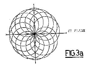

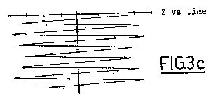
Figure 4 is a graphic diagram of ion density as a function of the radial distance from the center of the migmacell (solid line) and of the current density in a migma as a function of said radial distance (dashed line).
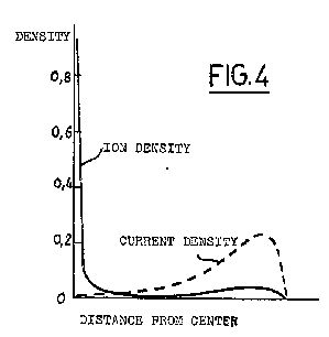
Figure 5 is a graphic example of the distribution of the intersecting angles of the deuteron-deuteron collisions in a migma orbit configuration such as shown in Figure 3a.
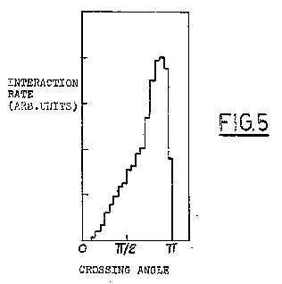
Figure 6 is an example of a graphic diagram of the energy distribution of ions in a migma in the laboratory frame of reference for the case of deuterons injected with a kinetic energy of 2.2 MeV and with an energy dispersion of 4%.
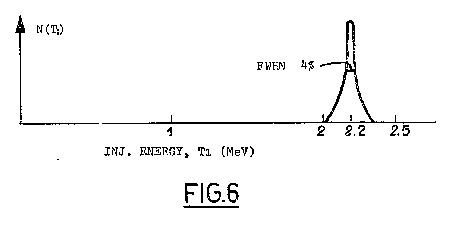
Figure 7 is a graphic diagram comparing the distributions of the kinetic energy in the rest frame of a single particle ("effective collision energy") for a migma (heavy line) and a plasma (dashed line) in the units of the injection energy.
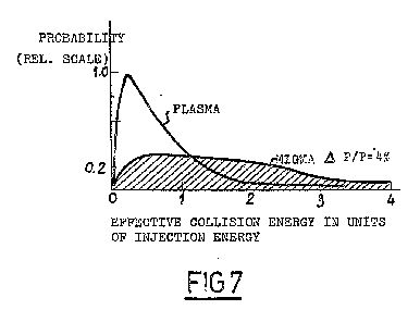
Figure 8 is a graphic diagram of the deuteron-deuteron reaction parameter, <delta v> (fusion cross section times relative velocity) averaged over a migma velocity distribution as a function of the injection energy; the operating points for the preferred embodiment as well as for the thermonuclear region are indicated.
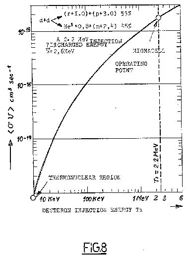
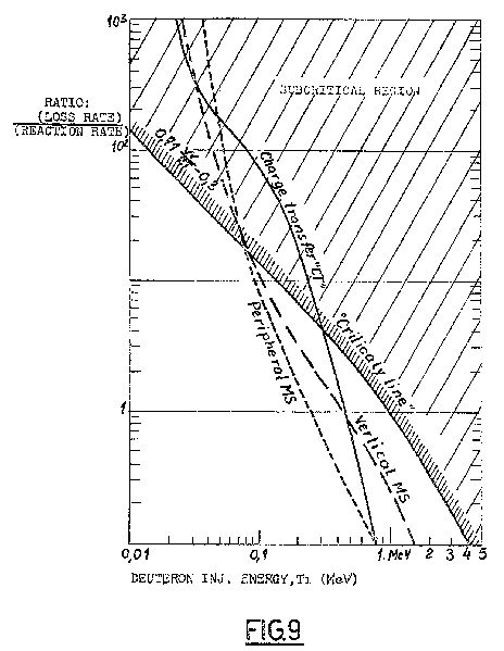
Figure 9 is a graphic diagram showing the ratio of the loss rates to fusion reaction rate in a d-d migma as a function of the injection energy for various loss mechanisms: (a) peripheral multiple scattering, (b) vertical multiple scattering and (c) charge transfer. The line (d) is the ration of the charged energy release in d-d fusion, 0.7 W over the injected energy 2T, minus 0.3 (the latter term following from the fact that a fraction of the injected energy is carried by the uncharged neutron). To have a net energy generation, the sum of (a), (b) and (c) must lie below (d). A vacuum of 10 -11 torr is assumed in computing the curve.
Figures 10a and 10b are respective top and side schematic diagrams of a migmacell system for direct conversion of fusion energy into electricity.
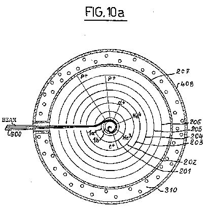
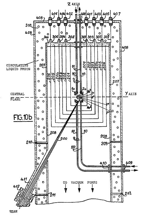
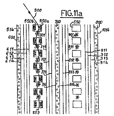
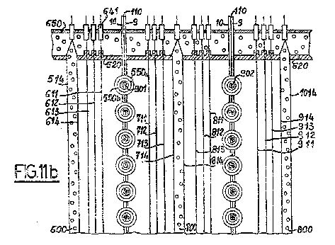
Figure 11a is a top view of a schematic of a part of a migma fusion reactor showing a portion of two migma columns, each of which may comprise 100 migmacells; Figure 11b is a side view of a schematic of part of a migma fusion reactor such as shown in Figure 11a.
Referring first to Figure 2a, the path of an ion 100 circulating in an orbit 101 off center in a magnetic field acting perpendicularly to the plane of the figure is shown. For concreteness, the large circle of radius R may be thought of as a pole tip. The ion orbit 101 has radius a ~ ½ R.
If the magnetic field is not homogeneous but decreases slightly towards the outside, that is, has the shape given in Figures 1a and 1b, the circular orbit 101 will not close, but will precess about the center of symmetry O1, as shown in Figures 2a and 2b. In Figure 2c it will be seen that orbit 101 reverses the particle velocity vector after half a precession period, ½ tp. If a second ion 200 is injected at that time with an orbit 102 as shown in Figure 2c, the two paths 101 and 102 meet head-on at the center OI, which facilitates a head-on collision between the between the ions and results in fusion, if the ions are deuterons or some other ions that can undergo a fusion reaction. The two orbits 101 and 102 continue precessing as shown in Figure 2d, about the center O1, maintaining their head-on collision configuration which, in turn, may result in about 108 multiple traversals, by the ions per second. This increases their collision probability by the same factor.
The described system of two revolving, and at the same time precessing, particle trajectories is similar to the common household dual-rotor mixer, which combines both rotor and the mixing bowl rotation. The main differences are: (1) the colliding orbits "rotate" in the same direction, which cannot be done in the cited mechanical system without rotor collision; and (2) a migma precesses typically at a rate of about 109 RPM, having no moving parts.
A more efficient orbit configuration is shown in Figures 3a and 3b, resulting from particles of like charge which have been continuously injected into the center of the magnetic field for one precession period or more so that the magnetic field region ios filled with orbiting particles.
The shape of the magnetic field and the radius of the migma orbits are predetermined so as to produce an automatic return to the central zone of all particles, by virtue of horizontal and vertical focusing by the field. Any perturbation of a particle in the central zone, such as caused by scattering between migma particles, will be overcome and the particle restored to its orbit within one revolution period by these forces, regardless of the energy transfer to it (or from it) during the collisions; and regardless of its angle, provided the vertical component of the perturbation is not above the vertical confinement angle of the device (i.e. the orbital angle with respect to the central plane above which the ion overcomes the vertical focusing forces and leaves the migma). This return effect is due to the fact that, contrary to the situation in plasmas, the migma orbits are large compared to the size of the device so that the field gradient across the orbit is large too, and the net focusing forces are felt by the particles in every turn. By way of contrast it should be realized that the gyroradius of plasma orbits is very small so that it takes very many turns of the plasma ion to move from the strong field region into a region of weak field (and vice versa) thus resulting in slow restoring forces.
This return effect is illustrated in Figure 3b for a vertical scattering through Oz = 10° and a field index k = 0.2.
This automatic return feature within the closed axially symmetric system makes a migmacell advantageous over the simple concept of two colliding ion beams as used in the previously mentioned CERN Intersecting Storage Rings. By comparison, a migma is the equivalent of an infinite number of colliding beams all intersecting at one point with all crossing angles confined to a single volume.
One simple shape of the magnetic field preferred for the migmacell which has the requisite precessing and focusing properties is given by the equation:
(1) Bz = Bo [ 1 - k ( r / R )2
---> 2k ( z / R )2 ], ![]()
where r is the distance from the axis of the field, R measures the physical size of the field, and k (<1) the field index determines both the strength of the vertical focusing and the precession rate.
An example of a simple coil configuration for producing a magnetic field such as given by equation (1) is shown in Figure 1c. Two pairs of coils 1a and 1b, and 2a and 2b are wound co-axially about a central axis Z in the same direction so as to carry current in the same direction, over respective stainless steel tubes 3a and 3b,and 4a and 4b. The opposing coils in each pair are equidistantly spaced from each other so as to define a central plane for the system, that is a plane perpendicular to the Z axis and half-way between the opposing surfaces of the respective pairs of coils, which is indicated by the line r in Figure 1c. The intersection of the Z-axis with the central plane will be the center of symmetry of the magnetic field and a central zone of the system which may be defined as a spherical volume with its center at the center of symmetry and having a radius of about 10% of the radial distance from the center of symmetry to the outer edges of the outermost coils 1a and 1b. Preferably, the opening between the outer edges of the outermost pair of coils 1a and 1b defines a radial angle B of approximately 45° with respect to the center of symmetry.
A pair of jackets 5 and 6 for conducting cooling agents is disposed about each of these sets of coils. For clarity, these cooling jackets 5 and 6 are only shown disposed about the lower set of coils in Figure 1c, but it will be understood that the system is completely symmetrical about the central plane. The inner jacket 5 may contain circulating liquid helium to facilitate superconductivity in the surrounded coils. The outer jacket 6 may contain circulating liquid hydrogen to facilitate removal of heat generated by stray ions from the migma which may strike and impart their energy to it.
To provide for the clearing fields for low energy electrons, two pairs of metallic plates 7a, 7b and 8a, 8b are disposed within the magnetic field as shown in Figure 1c at suitable electric potentials with respect to one another with polarities as noted in the figure. The combination of the two pairs of plates makes the average electrical field felt by a precessing ion equal to zero if the right-hand pair of plates 7a, 7b sets up an electric field opposite in sign but equal in magnitude to the left-hand pair of plates 8a, 8b. Each of the plates may be approximately semicircular in plan view.
Superconducting leads 9 and 10 to the respective cooling jackets 5 and 6 as well as the leads 11 and 12 to the clearing field plates 7a and 8a, respectively, are shown in the upper part of Figure 1c only. The stainless steel bar 110 between the leads 9 and 10 provides rigid support.
The precession period tp and the revolution period tR (cyclotron period) are related approximately by:
(2) ![]()
For the preferred embodiment k = 0.8, a = 2 cm, Bo =
200 Kgauss, v = 1.5 x 109 cm (2.2 MeV
deuterons), tp ~ 3 x 10⁻⁸ sec. The preferred
embodiment will be described in terms of the injection and
collisions of 2.2 MeV deuteron ions producing the fusion
reactions: d + d --> He3 + n and d + d --> t +
p and releasing about 2.6 MeV per reaction in charged energy on
the average. However, all the statements are generally valid for
all kinds of fusion reactions, for example, d + t --> He4
+ n and d + Li6 --> 2 He4.
It is apparent from Figures 3a and 3b that both the radial and vertical density of particles in a migma are highly peaked in the central zone. The migma density, that is, ion density, as a function of the distance from the center is shown by the solid line in Figure 4.
This is one of the advantageous features of a migma. The particles are concentrated so much in the center where the particles have large relative velocities, v12, that the probability of fusion reactions is greatly enhanced. Typically, 50% of the reactions occur in 2% of the radius.
Hence, a migma may be thought of as a spherical "core" on the order of 1 mm in radius, surrounded by a "cloud" of root mean square radius of about 3 cm which is relatively inert. These dimensions are given for a preferred embodiment (2.2 MeV deuterons in a central field Bo = 200 Kgauss and the field index k = 0.8).
Because of the high density and high relative velocities at the center, most Coulomb scattering will occur there. However, since it is a property of the migma configuration that any particle leaving the center will be returned to the center, the losses due to Coulomb scattering will be reduced by orders of magnitude from those that would occur in a colliding beam system. An additional mechanism that reduces multiple scattering losses is the restoring force of the radial and axial focusing of the magnetic field described by Equation (1) and Figures 1a and 1b.
The current density c = distribution in a migma is also shown in Figure 4 as the dotted line. It should be noted that where the charge density is highest (at the center), the current is zero. The magnetic field due to this current is a negligible perturbation to the guiding field.
A further advantageous feature of a migma is that, while all crossing angles from 0° to 180° are allowed, the average crossing or intersecting angle is about 155° since it is very likely that two orbits will overlap somewhat so that there will be two intersections between them near the center. Thus, the near head-on collisions are enhanced. This is shown in the plot of Figure 5.
The energy distribution of particles in a migma is distinctly non-Maxwellian, being very sharply peaked at the injection energy (see Figure 6). The effective energy dispersion which combined the energy and angular spread (emittance) is made sufficiently large to avoid the negative-mass and other known accelerator type instabilities.
The effective kinetic energy of the collision of an ion with injection energy T1 is seen by another ion of the same mass at an angle a is given by T12 = 2T1 ( 1 - cos a ). Since the average crossing angle is a = 155° , the average effective collision energy is about 4 times the injection energy. As a result, unlike in a plasma, 80% of the particle pairs in a migma collide at an energy greater than the injection energy. This is seen in the plot in Figure 7.
The energy distributions shown in Figures 6 and 7 are true only at the time of injection however. The multiple collisions will gradually spread the special extent of the migma, which, in turn, will lead to losses of fast particles and eventually "thermalize" the distribution down to Maxwellian. But, this process is comparatively slow and the fusion energy will be extracted long before this happens.
For instance, the d-d relaxation time for 2.2 MeV deuterons is of the order of 103 seconds. In contrast, the present intention is to store and siphon off energy of the order of 1% of the total potential migmacell energy in about 1 second and to refill the migmacell in the same time, thus maintaining the non-thermal energy distribution shown in Figures 6 and 7 by virtue of this continuous regeneration.
An important advantage of the migmacell is that the particles in the preferred embodiment will be injected with energies above 2 MeV as opposed to energies of 1-10 KeV in current plasma machines. Figure 8 shows the benefit of the higher energies in larger fusion parameter <dv>, where the averaging was done for migma velocity distribution.
It will be noted that two head-on colliding deuterons of 2.2 MeV correspond to about a 10 MeV laboratory deuteron incident on a stationary target. In terms of kinetic "temperature" --- if it has meaning here --- 10 MeV corresponds to about 1021° degrees.
Unlike in a plasma, the kinetic energy of the fusion products is of the same order of magnitude as the kinetic energy of the primary deuterons, thus it can be recuperated by the same technique used to extract the kinetic energy from the fusion products. The relatively low migma density allows the singly charged products to fly out of the reaction volume without interacting. Thus by disposing an array of positively charged plates outside of the reaction volume all of their energy can be recovered directly as electrical energy.
Furthermore, by choosing a relatively high kinetic energy for the injected deuterons, the fusion reaction products are highly peaked along the velocity collision direction. Since the collision direction in the central zone lies in (or nearly in) the central plane, and most of the fusion reactions take place in the central zone 90% of the charged fusion products leave the zone within a radial angle of about 22.5° about the central plane, without interacting with the field coils.
The present fusion method is therefore "non-thermonuclear" because no attempt is made to heat the ionized deuterium gas to thermonuclear kinetic temperature, 1 to 10 KeV. The present method starts with accelerated ions about 1,000 times more energetic and in the form of beams; and fires them against each other in a special manner. The energy distribution is not allowed to become Maxwellian in a migmacell. The magnetic field which confined the migma is more a guiding field than a "pressure field", as it is required to contain particles of only one charge and having a very restricted set of momenta and positions. In contrast, the magnetic field of plasma devices must contain particles of both signs having a great variety of momenta and positions.
And finally, since it is an essential part of the device to remove the electrons from the migmacell by means of clearing fields, such as by the pairs of plates 7a, 7b, 8a, 8b shown in Figure 1c, and keep the electron/ion ratio at the 10-2 level or less, the electron ion thermal equilibrium --- an essential feature of plasma --- is meaningless here. The consequence of the absence of the electrons is that the energy losses due to synchrotron radiation and bremsstrahlung are absent in a migma.
The maximum total number of ions, N, that can be stored in a migmacell is determined by the "Space Charge Limit". This limit is reached when the electrostatic repulsion of the migma on an iuon becomes equal to the focusing restoring force. The space charge limit N is for the preferred embodiment with a magnetic field of Bo = 200 Kgauss and 2.2 MeV deuterons:
(3) N = 4 x 10¹² ions
N is proportional to the injection energy to the 3/2 power.
The fusion reaction rate I of a migmacell is proportional to N2 and is approximately given by:
(4) I = 1 x 1025 <dv> fusions per second.
Which for 2.2 MeV deuterons gives from the diagram in Figure 8,
(5) I = 2 x 10¹⁰ fusions per second.
This gives a net charged power production in a steady state regime in which the losses are continuously replenished by new injection:
(6) Net Power = 3 m Watt per migmacell
Criticality Condition for the Migmacell Source ~
The condition for a critical power source is obtained from the requirement that the electric energy output be at least equal to the energy input, the input rate being balanced by losses. The three main loss mechanisms in a migmacell are: (a) peripheral multiple scattering, (b) vertical multiple scattering, and (c) charge transfer in gas (see Figure 9). If T1 is the deuteron injection energy, the charged power output, W, to total power input has been found to be:
(7) 0.71 W / 2T1 = 0.3
The sum of the ratio of all three losses to the fusion rate must be smaller than the value of Equation (7) in order to achieve a critical power source. Referring to Figure 9, this implies that the sum of all three curves (a), (b), and (c) must be below the "criticality line" given by Equation (7). We can see that this condition is easily met for deuteron injection energies above 0.5 MeV.
Energy Gain Factor of Migmacell Power Source ~
To determine the energy gain factor in a migmacell ocnsider that the gross power output P+, and the power input in the quasi steady-state regime P- may be expressed as:
(8) P+ = I Fc ( W + 2T1 )
(9) P- = I ( 2 + > ) T1
where I = fusion reaction rate; Fc = charged fraction of the average reaction energy W, T1 = injection energy and lambda the leak losses, which are added to reaction losses 2T1. Equation (9) means that the deuterons are replenished at their loss rate --- the factor 2 comes from the fact that each fusion process removes 2 deuterons from the migma.
The "energy gain factor" of the migma power source G is defined as:
(10) ![]()
Since for the d-d reaction Fc = 0.71, and W = 3.655 MeV, the maximum gain factor (lambda = 0) for injection energies of 0.5, 1 and 2.2 MeV are G = 230%, 100% and 29% respectively. With leak losses of 20% (lambda = 0.2), G = 200%. 82% and 18% for T1 = 0.5, 1 and 2.2 MeV respectively. On the other hand the absolute rate of power production is proportional to T12. Let is define as the earning factor E the product:
(11) E = G T12
Taking into account that the leak losses lambda also decrease with the increase of energy, it can be shown that the optimal earning factor E is obtained at the highest possible injection energy T1. This will be shown hereinafter to be 2.2 MeV for a breeder reactor.
The Method of Injection ~
The method of injection and trapping of ion beams into a migma, which will be called "self-snaring" will now be more fully described. It makes use of the salient property of self-colliding orbits, that is, the high central density, to trap the injected beam by interacting with itself.
There are two types of self-snaring: (1) the self-ensnaring of atomic ions, which will be referred to as "self-trapping" and (2) the self-ensnaring of molecular ions, referred to as "self-capturing".
Self-Trapping is based on the multiple Couloimb scattering in the central region of a migma. In a small region at a large radius of the main magnetic field, a perturbing local field is created. This local field may be in the form of a "magnetic channel", such as described in the text "Particle Accelerators" by M.S. Livingston and J.P. Blewett, p. 309, et seq. (McGraw-Hill 1962), and is created in a manner well known in the synchrocyclotron beam extraction art. The magnetic channel will differ from 1-10% in strength from the magnitude of the main field given by Equation (1). Ions are injected into the center of symmetry of the field from the periphery through this magnetic channel. By coordinating, in accordance with synchrocyclotron principles, the injection angle, the shape of the magnetic channel, the magnetic field strength and ion energy, the ion may be kept inside the field for many precession periods without violating the well-known Liouvilles’s theorem. If the ion is injected at an angle phi z to the vertical plane so as to induce vertical oscillations, these combined with the precession will keep the particle from returning to the entry point for say, v precession periods, or for the time v tau p. Note that this time is a metastable containment, because it does not change the density in phase space. It is suggested by orbit studies that for phi z = 10 degrees, the ion can be kept in the migma for 40 precession periods, (v = 40). During the artificial confinement the ions undergone Coulomb interaction between themselves, thus changing their density in phase space and gradually resulting in a stable confinement. This requires a very fast buildup of the central migma density --- a high instantaneous current Io. The density will increase linearly with time while the scattering rate increases quadratically.
The instantaneous current Io needed to have 50% particles escape the injection point after precessions is given by :
(12) ![]()
where <dv>ms is the product of the cross-section for deviation through an angle delta phi by multiple scattering averaged over the migma distribution. A Monte Carlo calculation shows for delta phi = 2.5 mrad, that <dv>ms ~ 10 -9 cm3 sec-1. For a field index of k = 0.8, tau p ~ 10-7 sec., so that with v = 40,
(13) Io ~ 10 Amps.
Such instantaneous currents can be obtained from pulsed ion sources (100 microsec. Pulse length) within the realm of present technology.
Self-Capturing is the process of injection of molecular ions which leads to dissociation collisions in the central zone in the same manner as self-trapping leads to multiple scattering. The processes are:
D2 + D2 4 --> 2D+ + e- + D2+; --> 3D+ + e- + D0; --> 4D+ + 2e-. Since the dissociated atoms have one-half of the injected momentum, all of them will find themselves captured.
The cross-section for the sum total of the three processes measured to be o ~ 1 x 10-16 cm2 at about 2.2 MeV, so that <ov> ~ 10-9 cm3 sec-1. This gives the same magnitude for the reaction parameter <ov> as that for multiple scattering (MS) beyond 2.5 mrad. Therefore, for self-capturing, the instantaneous current needed is also given by Equation (13).
Method of Breeding Fusion Fuel ~
A further benefit is obtained by injecting the deuterons into the system with energies within a particular range so as to produce a "breeding" effect. This improved method wherein the injected deuteron-deuteron migma is converted into a deuteron-He3 migma which releases 7 times more ion energy per fusion will now be described.
A deuteron-deuteron migma yields 3 charged fusion products from the following two reactions:
(14) d + d --> t + p + 4.04 MeV (55%)
(15) d + d --> He3 + n + 3.27 MeV (45%)
Since He3 is doubly charged, it will be appreciated that under certain conditions, the exit of the He3 ions from the migma can be prevented while letting the tritons and protons fly out, to give their energy to an outside electrical system. This latter condition is achieved when the deuteron injection energy T1 is greater than a certain value given by:
(16) T1min = 0.1154 W (dd --> He3 n ) = 377 KeV
With Equation (16) satisfied, the migma will be continuously enriched by the retained He3 ions which, in turn, collide with the deuterons from the migma producing another fusion reaction:
(17) D + He3 --> He4 + p + 18.34 MeV
It can be easily shown that in order to extract the energy from the reaction (17) by extracting both the doubly charged He4 and the proton from the migmacell, another condition has to be imposed unto the injection energy T1. This condition is achieved when T1 is less than a certain value given by:
(18) T1max = W ( d He3 ) / 8 = 2.29 MeV
If the conditions of (16) and (18) are both fulfilled at the same time, the He3 ions will stay inside the migma while all the other charged fusion products will exit. Thus, the appropriate conditions for fusion fuel breeding occur when the deuteron injection energy lies between the limits given by:
(19) 0.377 MeV < T1 < 2.29 MeV
It will now be seen that based on Equation (19) we chose an injection energy T1 = 2.2 MeV for our preferred embodiment, although the breeding will be inoperative for a range of T1 within the limits in (19). With:
(20) T1 = 2.2 MeV
the charged fusion products exiting from the migmacell will have the following energies:
(21) triton (t): Tt1 = 2.2 MeV
proton from d-d (p):
(22) Tp1= 6.33 MeV
proton from He3-d(p):
(23) Tp = 17.97 MeV
(24) He4: T4 = 4.49 MeV
while the He3 ions whose energy will be:
(25) He3: T3 = 1.92 MeV
will be contained within the migmacell and the migma will be continuously enriched by the high-power fuel, thus increasing the power output beyond the values given by Equation (6), as well as the energy gain values computed from Equation(12).
Broadly speaking, then, breeding is accomplished by matching the migmacell radius R to its average magnetic field B to satisfy the following relationship:
(26) ![]()
where T1 is the d+ ion injection energy in KeV, given by the limits in (19) and B is in Kilogauss, Equation (26) along with (19) defined the conditions for maintaining the He3 in the migma while extracting all the other fusion products from reactions (14), (15), and (17), thus promoting breeding.
Direct Conversion of Fusion Energy into Electricity ~
A means for converting the energy of the charged products of the fusion reactions as well as for recovering the energy of the primary injected ions will now be described. It is based on the following facts:
(1) At the high colliding energies considered, 90% of the products of fusion reactions are emitted at within 45° of the collision plane which is nearly the horizontal plane.
(2) In the d-d reaction, 71% of the fusion energy is carried by the charged particles and 100% in the He3 + d reaction (breeder mode).
(3) With the deuteron injection energy of 2.2 MeV, the charged fusion product ions carry the energies stated in Equations (20)-(25).
Although the magnetic field strength is designed to contain both the He3 and the deuterons, some of these ions will leak out of the migmacell as the result of single and multiple elastic scattering and the space charge effects ("leak losses") at a rate of about 10% of the fusion products rate.
Since He3 and He4 are doubly charged, they can be decelerated and fully stopped by positively charged plates placed in their path at potentials of 0.96 and 2.2 MeV respectively.
The tritons, the protons from d + d fusion, the protons from He3 + d fusion, and the primary deuterons may be stopped by plates at 2.2, 6.3, 18 and 2.2 MV respectively.
It will be noted that nearly the same potential stops He4, tritons, and deuterons. This permits the use of four plates to stop the six kinds of particles listed in Equation (20)-(25). However, for practical reasons, it is advisable to subdivide the gaps between the plates, so as not to exceed 400 KV per gap.
Figures 10a and 10b are a top cross-sectional view and an elevation, respectively of the migmacell shown in Figure 1c enclosed by a plurality of cylinders of which only seven, 201-207, are shown for simplicity. The cylinders, 201-206 are thin (5 micron) aluminium foils stretched onto a copper mesh of about 98% transparency as frames for rigidity. The outermost cylinder 207 is made of about ½ cm thick copper. All the cylinders are embedded at their upper ends into an insulating plate 300 made of isostatically pressed high alumina ceramic, with respective high voltage connectors 301-307 for each plate. The superconducting leads 9 and 10 held by stainless steel supports 110 between them provide mechanical support for the upper and lower pairs of coils, with the open space between them defining the reaction region.
The whole system is immersed in a jacket 408 through which liquid Freon is circulated by piping upwardly from below as a cold liquid and back down as a warm liquid at a rate such that the Freon never becomes a gas, and using known cooling techniques.
The migmacell coils 1a and 2b, as well as the leads 9 and 10 are at ground potential. The cooling jackets 5 and 6 are not shown in Figures 10a and 10b. The cylinders 201, 202 and 206 are at positive potentials of 0.8, 2.2 and 6.3 MV respectively. Cylinders 203, 204 and 205 are at about 3.5 and 5 MV respectively. A plurality of cylinders not shown in the drawing is put between each pair of cylinders in a well-known manner to provide a gradual voltage distribution.
The outer cylinder 207 is used to stop the 18 MeV protons from the He3 + d fusion reaction by the combined action of the features: (1) a decelerating voltage in the range above 6.3 Mv and up to the energy of the proton 18 Mv; and (2) the stopping power of the thick plate and the liquid Freon. Therefore only a fraction of the energy of these high energy protons is expected to be converted into electricity. The remaining energy will be converted into heat and carried away by the circulating liquid Freon.
The bottom of the copper cylinder 207 is sealed to a pyrex glass cylinder 208. A set of 8 tungsten pins (of which 4 are shown 209-212) provides support to an outside jacket 408 made of isostatically pressed high alumina ceramic. High voltage feedthroughs 400-407 are used for the respective leads.
Through this cylindrical arrangement, the 2.2 MeV deuteron beam 500, focused at the center of the migmacell by a system of quadrupole lenses 412 is injected through a tube 411 at an angle of 30° to the vertical into the lower coil of the migmacell to produce the migma and the resultant electric power output.
Migma Fusion Reactor ~
A migma fusion reactor may be constructed comprising a plurality of migmacells. In a preferred embodiment, 100 migmacells are stacked in a column, called a "migmacolumn" and a matrix of 100 by 100 migmacolumns may be used to make the reactor.
A top view of a section of two migmcolumns in a preferred embodiment is shown in Figure 11a. The elevation view of the same is shown in Figure 11b. it is seen in Figure 11b that each migmacell is suspended by its stainless steel bar 110 sandwiched between the superconducting leads 9 and 10.
A technical advantage to be obtained with a migmacolumn configuration over that of a single migmacell (Figure 10a and 10b) is that the positively charged repulsive cylinders can be replaced by plat plates, comprising thin metal foils stretched over a 98% transparent copper mesh.
Referring to Figures 11a and 11b, the plates, 611, 711, 811 and 911 are placed at a potential of +0.8 MV; plates 612, 712, 812 and 912 are at +2.2 MV; and plates 613, 713, 813 and 913 are at 6.3 MV. A plurality of plates not shown in the drawings is put between each pair of the above-cited plates in a well-known manner to provide a gradual voltage distribution. Plates 514, 614, 714, 814, 914 and 1014 of ½ cm thickness are placed at a decelerating voltage in the range from above 6.3 MV and up to the energy of the proton from the He3 + d fusion reaction, 18 MV, to stop it by the combined action described in connection with outer cylinder 207 above.
All of the plates are suspended from a plate 620 made of isostatically pressed high alumina ceramic and connected to a high voltage source through connectors 641. Plate 650 is made of the same insulating ceramic.
Plates 514, 614, 714, 814, 914 and 1014, together with plates 620 and 650 provide a jacket for circulating liquid Freon in the manner described in connection with jacket 408 above.
It will be seen from Figure 11a that while two pairs of coils are used for a single migmacell, in a migmacolumn three pairs of coils will act to provide the magnetic fields for two migmacells, so that in general, N + 1 pairs of coils will provide the field for N migmacells. Therefore, for a migmacolumn of 100 migmacells only 101 pairs of coils, 550a and 550b are required.
It should be noted that migmacolumns are not made up of a number of physically independent migmacells, but are rather a system of coupled migmacells. An advantage of this coupled configuration is that when all of the cells are filled with a migma, the end losses through the escape cone, defined by the vertical confinement angle, along with the Z-axis is reduced by the number of cells in the column, This is accomplished by the following automatic mechanism.
If a deuteron enters the escape cone of one migma cell, that is, starts moving, as a consequence of the multiple Coulomb scattering, through the cell coils into the next migmacell, the combined action of the sharp repulsive potential of the migma in the next cell and the Coulomb scattering therein are such that the probablility is 50% for the ion to deviate away from the Z-axis and stay trapped in the new migmacell with new initial conditions, thus contributing to the fusion rate.
The filling of a migmacolumn utilizes the same 60° injection technique as the filling of a single migmacell except that the ion injection rate is adjusted such that only a small fraction, approximately 1% of the ions, become self-ensnared in each cell in the column. The remaining ions enter the next cell, precess in an artificial confinement mode and, if not captured continue into the following cell, following the trajectory 999.
The filling time for a migmacolumn is approximately 10-4 sec. The accelerated ion beam 900 is then shifted to the next migmacolumn according to the well-known technique of two-dimensional scanning developed by the High Voltage Engineering Corporation for ion implantation and for accelerating and scanning micrometeorites in the NASA Space Program. Refilling is performed periodically in intervals of the order of one second or longer as may be required by the need to replace the deuterons lost through fusion and leaks.
What We Claim Is: --- [Claims not included here]
Top ~ Previous ~ Next (Tech Report)