Louis
MAICHE
Wireless Telluric Telephone
Wireless Telluric Telephone
Jerry Vassilatos : Vril Compendium
https://books.google.com/books?id=de5OAAAAYAAJ&pg=PA477&lpg=PA477&dq=Louis+MAICHE&source=bl&ots=0MwfiZciry&sig=ePs25QJg3djFbnx_ln0ivOIyIWg&hl=en&sa=X&ved=0ahUKEwjo8MGdhYHQAhVJl1QKHXecD3oQ6AEITjAJ#v=onepage&q&f=false
The Christian Work and the Evangelist, Volume 82
Wireless
Telephone of Louis Maiche, the French Scientist
https://books.google.com/books?id=euDmAAAAMAAJ&pg=PA79&lpg=PA79&dq=Louis+MAICHE&source=bl&ots=1k4NAB8mnd&sig=NTExYinKMaUfIbhxtExc0kaKA-0&hl=en&sa=X&ved=0ahUKEwjgp8uehoHQAhVj0FQKHeFyDlk4ChDoAQgbMAA#v=onepage&q&f=false
Telephony, Volumes 3-4
http://www.telephones-anciens.org/l-maiche-electrophone-a-pupitre/
L.Maiche électrophone à pupitre

http://www.lookandlearn.com/history-images/M240118/Maiches-wireless-telephone-system-1906?img=15874
Maiche's
wireless telephone system, 1906

http://thethingsienjoy.blogspot.com/2013_04_21_archive.html
The
world's first "mobile" phone (in 1906)
French inventor Louis Maiche and his wireless phone, arguably also the world's first mobile phone.
Image published in the Swedish weekly Hvar 8 Dag in September 1906 ( Click to enlarge )
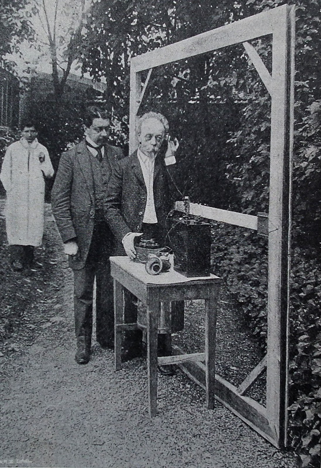
That is how an article in the Auckland Star on March 6, 1907, introduced the French inventor Louis Maiche, who also could be called the inventor of a mobile phone.
In the article M. Maiche describes how it all began:
"My first trials took place in 1867, but they were concerned more with wireless telegraphy, and it was not until 1893 that I exchanged a conversation through a wireless telephone at a distance of 30 yards."
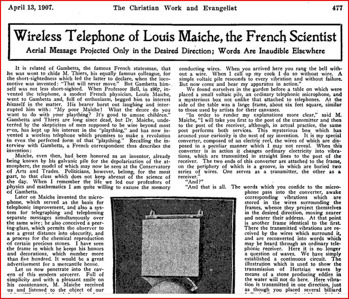
Two months earlier, the New York Times had also published an article on M. Maiche and his wireless telephone invention. In the article the inventor refers to his successful experiments with telegraphy and then describes his work with the wireless telephone:
"I then made use of the ground as a means of transmission. The discovery of today enables me to do away with all visible means of communication and to project the words in any given direction without the danger that they may be radiated elsewhere; and, more interesting still, I do this with an infinitesimal expenditure of electricity, while, as you well know, other wireless telegraphic and telephone systems expend enormous amounts of electricity radiated in all directions."
"When once perfected my apparatus may be practically used at an insignificant cost. Just now it is still at the laboratory and experimental stages."
"You see", said M. Maiche,"that our experiments have succeeded in spite of all obstacles. Neither the water, nor rocks, nor ice can interfere. All that the telegrapher considers as insurmountable barriers we easily pass through. Surely we have much to perfect! All that we have done up to the present is to be able to converse distinctly up to a distance of a little over 1,800 feet. But once the practicality of the theory is established, then the mechanism must be perfected."
"It is being perfected day by day - just as Branly one day succeeded in modifying the conductibility of his tube fillings from one end of his laboratory to the other, thereby making wireless telegraphy an established fact. And it will the same with our wireless telephone,which seems to us called to a very different destiny, not as aid to war, but as an aid to peace, as a savior of human life."
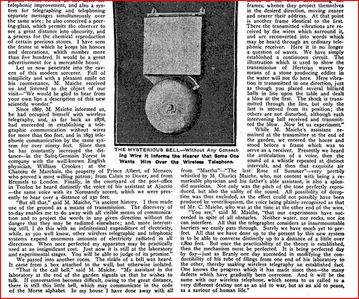
In the Auckland Star article M. Maiche gives some examples of the future use of his wireless telephone:
"Imagine two steamers steering through a fog. With my little apparatus the captain can tell the direction the other ship is taking. In case of an accident to a submarine my apparatus would enable the crew in danger to communicate with the convoying tug without fearing the breaking of a line as in the case of a telephone buoy. Miners entombed after a disaster like that at Courrieres could communicate with the rescue party. Two army corps making a night attack could keep in constant touch without risk of interruption. The ordinary citizen could have it in his drawing room, and would no longer be dependent upon the vagaries of the telephone exchange."
Both articles also include some technical descriptions of the use of M. Maiche's new wireless phone. It is possible that the French inventor's theories were not as successful as he himself thought. Otherwise it is difficult to understand why this page (in French) is the only one with information about him that I have been able to locate. Still, his concept of wireless (and mobile) telephony should merit him a place in the hall of fame of modern communication technology .
Patents
Nouveau
mode de transmission et de réception sans fil des signaux
électriques
FR335990
1904-02-22 FR335990
The object of the present invention is a new method of transmitting and receiving wireless electrical signals. The essential means on which is based the system is the production transmits position and uses the position receiver electricity manifested in a new form which may be referred to as "electrostatic vibration" and is obtained as will be explained further by modification of a spark inductor. One of distinctive characters of this new manifestation of electricity is that it can be transmitted in space without the aid antennas and ground at all distances, and, in the same form as sound, light and heat, that is to say without poles.
The inductor being communicated c with a power source, a battery, for example, and a special switch which will be described below, each interruption is to be born in the armature current giving a spark, and it is the latter that is transform an "electrostatic vibration." The armature out of the coil wire after the last winding outside, is for this purpose connected to a large metal surface which can be exposed to air. This surface may be constituted either by c a hollow or solid cylinder or by one or more sheets of iron, copper or any other metal usual more or less thick. The surface is preferably rounded at the corners or packed with a border all around to remove spikes, as in the conductive electrostatic machines. It should be about one square meter per watt of the current flowing in the inductor. The other end of the armature is connected to an adjusting screw of which the tip k of platinum or gold is next to a button, also in a gold or platinum, carried on the large surface.
FIGS. 1 and 2 of the accompanying drawings show two provisions which may be 5 h adopted for the preparation of the transmitter station.
FIGS. 3 and k show two provisions and receiver.
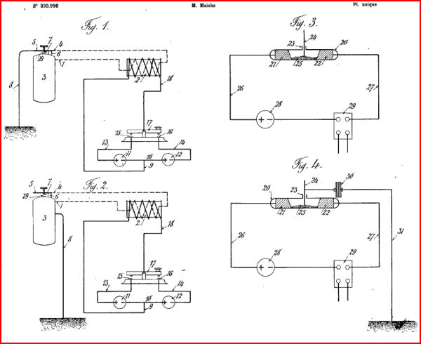
One end of the armature wire of the coil -j is connected to the cylinder 3 rounded at its ends, and the end k of the wire is connected to plate 5 mounted on the insulating support 6 which is fixed to the cylinder 3 . The plate 5 is traversed by a setscrew 55 provided beyond tip 7 made of gold or platinum. The end of the induced wire k is that by which begins rolling on a bobbin. Wire 8 communicates with the earth or the plate 5 (Fig. I) is the cylinder 3 (Fig. A).
Improvements
in and relating to Electric Transformers.
GB190727157
1908-10-29GB190727157
Comprises a large number of windings wound in the form of a cable a on a coreless frame b, and led out to terminals 1 ... 10 and, adapted to be connected in quantity or tension by means of a commutator so that three or more independent circuits may be made.
COMPLETE SPECIFICATION.
The present invention relates to electric transformers of the class described by Specifications Nos. N;821901 (Amberg), z1854 (Swinburne), and 4/I83 (Clerc) and it particularly concerns the arrangement of the windings.
The invention is represented in the accompanying drawings;-
Figs. 1 and 2, show a section and a front view respectively of the improved transformer.
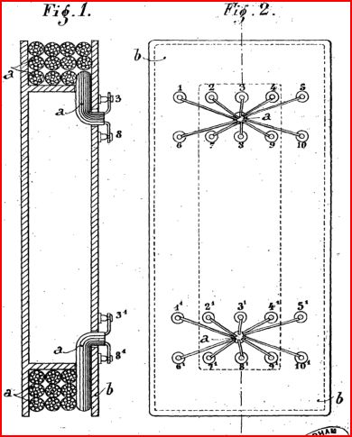
The transformer which has no magnetic core, is merely constituted by a convenient number of insulated wires, 10 for example, which are united to form a cable a which is wound around a frame b. The ends of the cable project through two holes of the frame and the ends of each wire are joined to terminals 1 to 10 and 11 to 101 respectively. In the drawings are shown 20 terminals, the first ten of which correspond to the beginnings of the 10 wires, and the other ten correspond to the ends of the same wires.
Thus, a winding of a certain number of identical wires is obtained which are all wound parallel and simultaneously and which may be connected by means of a commutator so as to form groups to 'be varied according to requirement; so that there are thus constituted three or more circuits which are entirely independent the one of the other and the length of which can be varied at will.
By conveniently joining the free ends of some of the wires, a primary winding of weak resistance is obtained with the wires of same joined for quantity, while one or more of the secondary windings are joined for tension, thus providing any required resistance.
The construction of the transformer by means of a great number of separate wires offers numerous advantages amongst which are the facility of connecting the separate wires at will to constitute the circuits; the arrangement enabling a supplementary circuit to be branched off at any point of the said circuits; and the reciprocal independence of these circuits with large number.
Improvements
in and relating to Electric Transformers.
GB190721535
GB190721535
1908-05-28
Transformers for telegraphy and wireless telegraphy are made without a magnetic core, and of little depth but of large diameter. They have the primary winding e enclosed within the secondary winding c, g, but separated therefrom by insulation d, f. The windings may be formed in sections, and coupled up in any order by means of a commutator.
COMPLETE SPECIFICATION.
This invention relates to electric transformers the construction of which is improved so that currents of induction of very short periodicity are obtained.
The currents, the duration of which is extremely short, possess special properties which are particularly useful when applied in telegraphy and in wireless telephony.
Transformers without magnetic core and with the secondary winding wound around the primary, or with the primary winding enclosed within insulating material round wh,ich is wound the secondary winding so that the whole forms a cable, have been provided, and my invention is limited to the form and construction of the transformer as hereinafter set forth.
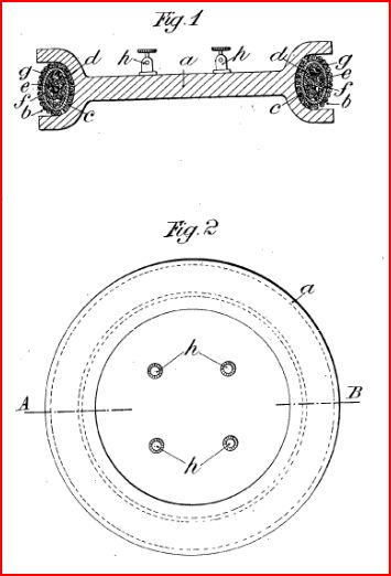
My improved electric transformer contains its primary wire within a cable of the secondary wires in the form of a single coil of little thickness but of very large dia,meter, said coil or cable being applied to a ring-shaped transformer body.
The accompanying drawing shows my improved electric transformer.
Fig. 1 is a section on line A-B of Fig. 2 and
Fig. 2 is a plan of the ring-shaped transformer.
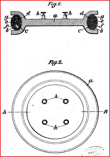
As will be seen from the drawings, the transformer a is of comparatively large diameter which may be several meters. In the drawing the transformer is represented of circular cross-section, it could however be of square or other cross-section. This transformer is very short because all the wires of the winding are located on its periphery in an appropriate hollow or groove b. For manufacturing the trans-former I place around the rim of this kind of wheel or dial: a, a first layer of secondary wire which is covered by a suitable insulator d and upon this insulator the primary wire e is wound which is covered by another layer of insulating material f. The two insulating layers d and f are connected in such a manner that the primary wires e are well insulated, and the coil is then finished by applying an outer winding of secondary wire g, the latter surrounding the primary in such a manner as to form a cable. In this manner a ring of large diameter is obtained which is composed of the secondary wires c, g which enclose a core of suitably insulated and wholly surrounded primary wires e and which ring is applied to a ring-shaped transformer-body having a peripheral groove of suitable cross-section.
The apparatus comprises four terminals h, two of which serve for fixing the ends of the secondary wires, the other two serving for fixing the ends of the primary winding.
There could be arranged several independent cables or rings in each of which the secondary wires entirely surround the primary wires and in such case each of the terminals would be replaced by a multiple commutator permitting to join up the different secondary wires as well as the different primary wires either for tension or for quantity according to the effect to be obtained.
Improvements
in connection with Wireless Telegraphy and Telephony.
GB190721252
GB190721252
1907-11-21
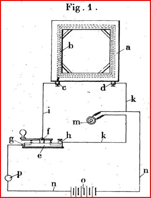
The transmitting and receiving circuits at one station for an inductive system of telephony or telegraphy are arranged as shown. A coil a, consisting of a few turns of thick wire, is used alone in transmitting, but is connected in series with a coil b, consisting of a large number of turns of fine wire, for receiving; the circuit of the coil b is broken automatically, during transmission, by means of a Morse key c. The circuit of the coil a includes a battery n and a microphone o for telephony, or an interrupter for telegraphy, and the coil b is connected with a telephone h.
There are known systems for telegraphy and telephony without connecting wires which utilise, instead of Hertzian waves, the phenomena of distant induction by means of electric vibrations of very short duration, but great amplitude. With such systems, one and the same winding is used fur sending and for receiving; for sending it is placed in circuit with a source of electricity (battery, accumulator, etc.) and with a microphone or an interrupter destined to produce the vibrations in question. The same winding is placed in circuit with a .receiving telephone .for receiving the currents which arc induced at a. distance from the sending winding of the other station.
It is obvious that this single coil cannot equally well serve for the sending as for the receiving. To transmit well it ought to be made from thick and short wire, whilst for receiving well it ought to be of long and thin wire.
It would evidently be the simplest to provide each station with two different coils of which one serves as transmitter and the other as receiver, but lucre is another difficulty to be considered; for receiving, the long and thin coil has to be closed by the telephone and in that condition it would absorb nearly all the energy which ought to be sent out by the transmitter.
The present invention rotates to a special method of mounting the parts constituting a station in order to overcome the above mentioned difficulty; besides, the special method of mounting permits to join the two coils one behind the other for receiving whereby the receiving power of the station is considerably increased.
The accompanying drawing represents diagrammatically a station according to the present Invention.
a is the inductor wire which serves fur transmitting; this wire is thick and relatively short. b is the induced winding for receiving the induced vibrations from the inductor winding of the transmitting station; this winding consists of thin wire of considerable length. c is a. Morse-manipulator the lever of which is connected through the contact let with one end of wire a, its connector e is through the contact f connected with one of the ends of wire; the wire g which connects the contact f with wire b comprises the telephonic receiver h ;the other connector i of the Morse apparatus is connected through terminal with the free ends of the two wires a and b which are joined at this point. The connecting wire m which serves for this purpose, comprises the battery n and the microphone o.
It is easily' understood that in the inoperative position of the Morse key (as represented in the drawings) the two coils and b form one circuit closed on the telephone h. This position is the receiving position. For transmitting, the key is depressed and brought in contact with the connector whereby the coil b is opened whilst the coil a is closed on the microphone and the battery.
It is to be understood, that the station described serves for the transmission of sounds. For the transmission of telegraphic signals, the microphone o is replaced by a suitable interruptor-vibrator and the apparatus is operated through the Morse key as usual.
Improvements
in and relating to Inductive Telegraphy and Telephony.
GB190712529
1908-03-12 GB190712529
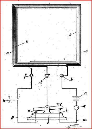
In a system of telegraphy or telephony by magnetic induction, the coils are placed vertically and the same coil is used for transmitting and receiving. The coil b is wound on a frame a of any suitable shape, which may be lined with iron. One terminal of the coil b is connected to a key f, one contact of which is connected through a microphone p and battery o to the other terminal d of the coil. A telephone m is connected across the terminals of the coil through another contact of the key f, and its circuit is normally completed for receiving telephonic or telegraphic messages. Telegraphy is effected by manipulating the kev f to complete the circuit of battery o ; to telephone, the key is depressed and the microphone p is utilized. A high-frequency alternator may be used instead of the battery o, and a screen composed of sheets of paper soaked in paraffin, varnish, or glue may be placed behind the frame.
The present invention relates to improvements in that class of magnetic induction telegraphy and telephony in which transmission is effected between similar coils of wire at the receiving and transmitting stations. The invention is characterized by the fact that senders and receivers.are reversible, the member for transmitting the waves being the, same as the member which receives the waves.
In the drawing, a diagram of a station according to the present system is represented.
The transmitter and receiver for the electric waves consists of a. wooden frame (a) of fairly large dimensions; for example 4 meters square for a distance of 20 kilometers. In the drawing the frame is shown as being square but it may be of any other geometric shape having as center a.rectangle a lozenge, a circle, etc. The wall of the frame is provided with a groove (b) in which an insulated conducting wire is placed which is connected with the terminals (c) and (d). This wire is wound a. varying number of times around the frame so that it is of sufficient length according to the power of transmission required of the apparatus.
The frame (a) must be of sufficiently large dimensions to prevent the currents generated in opposite directions in the sides of the frame from tending to neutralise each other.
Each station comprises besides a Morse manipulator (e), the commutator of which is connected with one of the terminals (c) of frame (a) through the wire, its terminals (r) and (h) being connected with the other terminal (d) of frame (a).
An ordinary telephonic receiver (m) is inserted in, the circuit (k) which leads from the terminal (h.) of the manipulator to the frame, and in the other circuit (n), connecting the terminal (g) of the manipulator with. the frame, a battery (o) is inserted near the frame and , microphone (p) is inserted near the manipulator.
When the manipulator (c) is at rest (position shown in the drawing) the station is ready to receive the transmissions, the electric circuit (a, c, i, f, m, k, d, a) enclosing the frame and the telephone -being closed. One has only to hold the telephone to the ear to perceive all the currents which a.re induced in the frame (a).
The telephone (m) is put out of circuit when the commutator (f) is pressed down, whilst t.he circuit will be closed upon the frame (a.) and battery (o). The station has thus become 11 sender, the battery sending variable currents into the frame according to the nature of the transmission to be effected. To telegraph according to the Morse alphabet one manipulates the commutator (f) in the usual manner, the telephone (m) of the other station permitting to distinctly perceive the dots and dashes. The operator simply gives one contact for the dot and two contacts following in quick succession for a dash. In this case the microphone (p) is superfluous but it does not disturb. When however one wants to telephone, the contact (g) has to be kept closed and one speaks in front of or into the microphone (p); the telephone (in.) of the other station will reproduce the sounds.
The source of electricity (o) can be a battery or an electro-magnetic generator giving alternating currents of high frequency. The currents which are thus sent into the frame (a) of the sender station have no appreciable effect upon the telegraphic receivers which could be provided at this station; they even do not influence the magnet needle owing to their illst,nntfmeousness.
To establish the communication between two stations the two frames (a) have to be placed in parallel planes, perpendicular to the line which would connect their centers, which can be effected through various means. The action (if the one of the frames on the other is effected through any obstacles whatsoever, no earth connection or air connection being necessary.
The reciprocal action of the frames can be increased through lining the bottom of groove (b) for its entire length with soft sheet iron, the lining being continuous or interrupted. The frame will thus become a kind of electro-magnet, the proportion of which are just the reverse of those generally used.
To communicate at very great distances several frames (n,) are joined up, the wires being joined up in series or for tension.
The efficiency can be considerably increased and the direction of transmission localised in avoiding dispersion at the sides or behind the frame, by means of a thick screen composed of superposed sheets of paper soaked in paraffn ; the paper could also be impregnated with varnish, glue or any other equivalent material.
Improvements
in and relating to Telegraphic and Telephonic Systems.
GB190126600
1902-11-06GB190126600
Relates to the arrangements of circuits in telegraph and telephone systems. In Fig. 1, a microphone b is shown in a main line a, and at the receiving-station is connected to the middle of a split battery f, g, two receivers l, m being connected between battery and earth. When induction coils are employed, two separate primaries take the place of the receivers in the Figure, and the receiver employed is placed in a common secondary. In another modification, the transmitter is bridged across two parallel closed circuits, including primaries and batteries, the secondary forming the line circuit.
This invention relates to telegraphic and telephonic systems and has for its object certain improvements hereinafter more particularly referred to and finally pointed out in the claims.
As is well known, in order to prevent over-heating of' the receiving and transmitting apparatus in telephonic or telegraphic installations it is necessary to prevent very strong current passing over them. It may however, in certain cases, be necessary to provide currents of varying energy within rather large limits, and this invention has for its object to provide a simple device which will permit currents of any force being passed through telegraphic and telephonic apparatus without the slightest risk of deterioration to such apparatus.
In order that my invention may be readily understood and carried into effect I will now proceed to describe the same fully with reference to the accompanying drawings wherein are shewn diagrammatically several methods of carrying my. invention into practice.
In the drawings :
Figure 1 shows the principle of my improved arrangement, and
Figures 2. and 3 are modified arrangements.
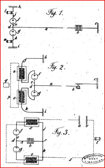
My improved system consists essentially of a line a of any convenient length in which is interpolated a microphone b or other appropriate transmitting apparatus. One end of this line is grounded at c and the other end is connected at d to.a wire e adapted to place into communication the opposite poles of the two sources of electricity of equal power, which for greater clearness sake I have represented as two single batteries f and g. These two batteries are respectively connected to earth at h and i. In the earth wires j and k are interpolated telegraphic or telephonic receivers l, m, of any convenient construction. In the example shown in the drawing the receivers and m are indicated as being telephonic receivers.
Having thus described the general arrangement of the system I will now explain the function of the various apparatus of the system.
Presuming that the wire a is non-existent and that the communication of the battery f and g with the earth has been established, a current passes from the positive pole of the battery f to earth through the wire then back .through the wire k, battery 9 and finally through the wire e to the negative pole of the battery f. Thus a closed circuit is established. Admitting now the wire a to be connected to the wire e at d and the transmitter b operated, the single current generated in the previous case will be replaced, by two currents which circulate in the same direction.
One of these currents starts from the positive pole of the battery f through the wire through earth from h to c through the transmitter b, wire a and wire e to the negative pole of the battery f.
The other current starts from the positive pole of the battery 9 through the 'wires e and a, the transmitter b, through earth from c to i and wire k to the negative pole of the battery g.
It will thus be seen that the wire a and transmitter b are simultaneously traversed by two equal currents in inverse directions.
In Figure 2 I have shown a telegraphic transmitter or key b but the general arrangement of the system is the the same as that previously described with the exception that the wires j and k form the primary conductors of the transformers n and o. The secondary conductor p, which is common to both transformers, leads,to the receiving apparatus q, for example a telegraphic receiving instrument.
Each contact ejected with the key b produces, as before explained a double derivation acting by subtraction of intensity upon the two transformers n and o, produces an induced current which is reproduced in totality in the receiving apparatus q. In the case of telephonic transmission the key must be replaced by a microphone as shown in Figure 1, while further the receiver q would also be a telephonic receiver.
By extending the same principle I can, as indicated in Figure 3, replace the two earth wires by two conductors and k joined together at r after having traversed the transformers x and o. The induced current may then be conveyed to the receiving instrument t over two lines, or as in the previous example over a line s and two earth connections u and v, placed more or less apart from each other.
It will be noticed that the microphone b forms part of the neutral conductors.
It acts exactly as in Figure 1. The differences of resistance produced by its vibrations influence the two coils x and o, and it is easy to understand that, whatsoever may be the intensity of the two electric sources f and g, the microphone is never exposed to the risk of becoming overheated for the reason that it is traversed by two equal currents in opposite directions.
It will thus be understood that the transmissions will be rendered perceptible in the receivers through the differences of intensity of the electric current; the differences being due to the differences of resistance of the neutral conductor which, in receiving two equal currents in opposite directions, is not much affected itself.
Improvements
relating to the Transmission of Telegraphic and Telephonic
Signals.
GB190117711
1901-02-19GB190117711
The local circuits at each station are doubly earthed at e, f, j, k symmetrically about a straight line joining the stations. The earths may be formed of porous pots containing water in which the ends of the conductors are immersed, or deep ditches filled with gas coke may be employed. Insulating screens may be placed in deep ditches dug behind the earths.
This invention relates to an improved method of transmitting electrical telegraphic and telephonic signals from one point to another without the employment of wires connecting the two points.
In my improved system of transmission, the two poles of the transmitting station are put to earth and the two conductors, upon which the receiving apparatus is mounted are also both put to earth; the signals emitted by the transmitting apparatus are transmitted to the receiving station through the earth alone.
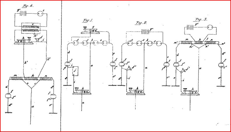
In order that my invention may be readily and clearly understood, I have represented in the accompanying drawing, by way of example only, a diagrammatic view of my device as a whole.
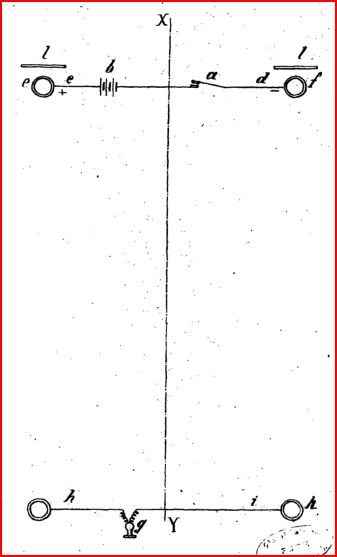
As shewn in the drawing, the transmitting station comprises a transmitter a one of the terminals of which is electrically connected to one of the poles of a source of electricity b whilst the other pole communicates with the earth; the second pole of the source of electricity is also run to earth and with this object the two conductors c d terminate in two porous pots e f embedded in the ground and filled with water.
The receiving station comprises a receiver 9 such as a telephone for example, the conductors h i which are put to earth by the intermediary of two porous pots j k similar to those of the transmitting station.
The porous pots of the receiving station should be arranged upon a line parallel with that which joins the two porous pots of the transmitting station, and they should be equidistant from an axis passing through the middle point of this line and at right angles to said axis.
The porous pots may advantageously be replaced by deep ditches sunk down to the humid earth, filled with gas coal or coke and containing at their centre a plate of carbon which is a good conductor, to which the transmission and receiving wires respectively are attached.
When contact is established by manipulation the transmitter a, the electric circuit passing through the source of electricity b, the conductor c, the porous pot e earth-connected to the other porous pot f the conductor d and the transmitter a, is closed. The current thus produced causes a change of condition in the ground ; all around the porous pots electric radiation is produced, the polarity of which is that of the corresponding conductor; its density decreases in proportion as it is further removed from the point of departure. This radiation is infinite with respect to space if nothing obstructs its passage.
The radiation extends so much the further according as the distance between the two porous pots of the transmitting station is greater.
These radiations, starting respectively from the porous pots e f thus create two zones one of which is positive and the other negative, the intersection of which constitutes % line absolutely neutral. It follows from this that the porous pots of the receiving station should be arranged upon either side of the neutral axis, because if these two earth connections were upon the same side they would both collect fluid of the same polarity, and in these conditions the receiver would not be traversed by any current.
In order to collect the maximum of current at the receiving station, the two porous receiving pots should be as nearly as possible equidistant from the neutral axis, as if one of the two porous pots is nearer than the other, the difference of separation of that which is the furthest removed is not only lost but is prejudical since it causes useless resistance without adding anything to the effect.
Experience has demonstrated that the disposition which furnishes the maximum of reception is that which consists in arranging the porous pots of the receiver at the same interval as separates the porous pots of the transmitting station.
In order to install my method of electrical transmission, it is first of all necessary to draw a straight line a y connecting the two stations and .then to produce upon each of these stations a line proceeding from this line x y at right angles, the said perpendicular lines being of equal length.
The transmitting and receiving appliances may be arranged at any convenient point on the conductor which connects the porous pots.
In order that the whole of the radiation emitted may be utilised at the receiving station, the propagation of this radiation is prevented (at the transmitting station upon the side opposite to that on which the receiving station is situated by burying in the ground an insulating screen l which may be of glass, tarred fabric, ebonite or the like, or by sinking a sufficiently deep ditch with or without an insulating screen.
Each time contact is made at the transmitter a, a sharp blow is audible at 'the receiving telephone g ; a second blow is heard when the circuit is broken.
It is obvious that there may be arranged both at the transmitting and receiving station transmitting and receiving appliances of the greatest possible sensibility, either for serving as relays for telegraphic purposes, or for directly receiving and recording the signals; for example an ink siphon mounted upon a galvanometric frame, or any other suitable device.
My method of transmission also permits of the transmission of speech; it is only necessary to replace the transmitter by an ordinary microphone interposed either directly upon the circuit, or arranged upon the primary of an induction coil, the secondary wire of which terminates at each extremity of the two porous pots.
It will of course be understood that in practice each station comprises both a transmitter and a receiver.
Improvements
relating to the Transmission of Electric Currents
GB190108906
GB190108906
1901-04-30
Telegraph and telephone systems are arranged with the line-wire a connected to the center point of a battery c, c, the opposite poles of which are earthed and shunted by a normally closed circuit key g or microphone. The earth connections are made through non-polarizable cells f, f, containing, for example, two plates of copper immersed in copper-sulphate solution. The receiver is bridged between one earth and a switch h by which the transmitter is normally connected to line. The microphone may be inserted in the primary of an induction coil, the two secondaries of which oppose and are connected to the two earths and line. The two earth connections may be brought nearer together by the receiver and switch in the primary of the induction coil, so that this coil acts both to receive and transmit according to the position of the switch h. The microphone is arranged in the primary of a second induction coil.
This invention relates to improvements in the transmission of electric currents and is more particularly adapted for telegraph and telephone lines, whereby condensation in the cable is avoided, while at the same time "tapping" of the , line at any point thereof, for the purpose of ascertaining the purport of the message in transmission is rendered impossible.
My improved system of transmission comprises a single line wire between the two stations and branched at these two stations to the zero point of a circuit, the two extremities of which are connected to earth or the sea ; the current furnished at each station by a local source of electricity being sent through the circuit by means of any convenient transmitting apparatus, (such as a Morse key, microphone or the like) either direct or by induction.
Each station is furnished amongst other apparatus, with a receiving apparatus consisting of a key-instrument connected with the line-wire and permitting the current sent into the line from the transmitting station, to pass into a conductor leading direct to one of the wires running to earth and to which is connected the receiver proper.
In order to avoid the polarization of the earth-wires, each such wire is connected with a conductor leading to a copper or other metallic blade immersed in an impolarizable saline solution in which is disposed a second similar blade connected to earth or sea.
In the accompanying drawings :
Figure 1, is a diagram showing my improved system as applied to telegraphy
Figure 2, is a diagram showing the same applied to telephony.
Figure 3 shows the system of Figure 2 with induced current.'
Figure 4, shows a modified arrangement.
In all the figures the same letters of reference designate the same parts.
Referring to Figure 1 the two stations are connected by a single line-wire a, branched at the zero point b of the battery formed of the different elements c of which the end poles are connected to earth, or to sea, by a conductor d e lead- ing to a copper or other metallic plate f immersed in a liquid of good conductivity, such as for example a solution of a sulphate of copper, in which another copper plate f1 is placed connected to earth, or sea by a conductor d1 .
A transmitting apparatus g of any convenient construction, such as a Morse- key instrument, is connected with the two end poles of the battery in such a manner that in its position of rest it closes the circuit of the latter by establishing a short circuit so that no current passes, (or at most a very weak one) through the wire line a or through the earth-wires.
To send a current to the receiving station, the key 9 is depressed whereupon the short circuit is interrupted and the current is caused to pass simultaneously through the line-wire a and the earth-wires d d1 e e*. The line-wire is in reality traversed by two currents in opposite directions, so that it is in an apparently neutral state, and thus no interception of the messages can be effected for the, reason that if a receiver be interpolated, at any point of. the line, said receiver would receive two currents in opposite directions' which would neutralize each other.
Each station is furnished also with a receiving apparatus consisting of a commutator h connected with the line-wire a and permitting, when depressed, the current from the transmitter to pass into a wire i leading direct to one of the earth-wires (d1 for example) and in which is interpolated the receiving instrument j.
To receive signals sent from the transmitting station, it 'is necessary that the commutator lever h be kept depressed, so as to cause the current from the transmitting station to pass into the wire In connection with the receiving instrument.
'The connections may also be established in such a manner that when the commutator h is in its normal .position, it cuts the wire ( and connects the wire with that part of the said wire which leads to the other station ; in this case for transmitting a signal it is necessary to depress the commutator lever h previously so as to re-establish the continuity of the line-wire and the operator then acts on the key-lever g as hereinbefore stated.
My arrangement is equally applicable to telephonic messages as will now be explained with reference to Figure 2, The transmitting instrument g is in this case replaced by a microphone g1 and the receiving instrument j is replaced by a telephone receiver j 1 the operation of the arrangement is exactly, the same as that above described.
The vibrations of the microphone cut the short circuit and the current from the local, source of electricity thereupon passes over the line-wire a and the earth-wires d d1 c el as previously stated.
The telephonic message is received in the same manner as before through the intervention of the commutator h which passes the current, sent from the transmitting station; to the telephonic receiving instrument jl.
The line-wire may also be operated by induction currents a3 is indicated at Figure 3.
The local circuit in which the transmitting apparatus (for instance, the microphone g1) is inserted comprises a primary winding k surrounding a central soft- iron core, or bundle of wires, l which is further provided with two secondary windings m m in opposite directions. The line wire a is connected to each of these secondary windings at the two extremities m1 n1 of opposite polarity and the opposite extremities ms p2 are connected with the earth-wires d d c set in the manner already explained.
When operating the transmitting apparatus or when speaking into the microphone 0 for example, induction currents are generated in the secondary windings m n and they then affect the receiving apparatus jl at the receiving station as already stated.
The primary winding and the two secondary windings may have the three wires wound in the same direction upon the soft iron core and the two extremities of the primary convolutions are connected with the local circuit in which is interpolated the transmitter while two extremities of opposite polarities of the secondary convolutions are connected to line and the two osiers to earth as previously explained.
In my improved transmitting arrangement the two earth wires at 'each station must be the more separated from each other the longer the distance is between the two stations so that the resistance of the earth between the said earth-wires will be sufficient to cause the single line-wire to be traversed by the greatest possible quantity of the current.
In order to reduce as far as possible the distance between the earth-wires the beginning of the single wire a and the wires rl rl' leading to earth are advantageously rm distance from the transmitting instrument and receiving instrument respectively at the telegraphic or telephonic station and thus permit the two earth connections of the two telegraphic or telephonic stations to be placed nearer each other.
The telegraphic or telephonic station is then divided and the transmitting instrument is connected with the magnet with its earth connections and line wire a ' by two conducting wires kl k2 connected with the ends of the convolutions k which generates induction currents in the secondary windings m n (Figure 4).
The current sent into the conducting wires k1 k2 and. passing through the convolutions k may itself be an induced current generated in the coil k3 when a current from the source of electricity c is passing through the. primary coil o through the action of the transmitting microphone gl for example.
In the case when' the distance of the telegraphic or .telephonic transmitting station from its earth-connections is not too excessive the current traversing the conductors k1 1.:2 instead of being an induction current may be furnished direct by the source of electricity of such station, and naturally the, transmitting instrument, (microphone or 'key), and the source of electricity are then placed direct in the circuit;1 k2.
An interrupter A interpositioned in the conductor kl permits of cutting the circuit in leading to the secondary coil k3 and of closing the circuit for the conductor i leading to the conductor k 2 in which is interpolated' the receiving instrument j.
Thus the coil k is either inductor or induction according to whether there is transmission or reception.
It is to be well understood that my system of transmission is entirely independent of the nature of the telegraphic or telephonic apparatus employed therewith, and that the source of electricity at the stations may be of any convenient kind, either derived from a battery, accumulators, dynamo, magneto-electric machine or the like.
COMPLETE SPECIFICATION.
This invention elates to improvements in the transmission of electric currents and is more particularly adapted for telegraph and telephone lines, whereby condensation in the cable is avoided, while at the same time "tapping" of the line at any, point thereof, for the purpose of ascertaining the purpose of the message in transmission is rendered impossible.
My improved system of transmission comprises a single line-wire between the two stations and branched at these two stations to the zero point of a circuit, the two extremities of which are connected to earth or the set; the current furnished at each station by a local source of electricity being sent through the circuit by means of any convenient transmitting apparatus, '(such as a Morse key .microphone or the like) either direct or by induction.
Each station is furnished, amongst other apparatus, with a receiving apparatus consisting of a key-instrument connected, with the line-wire and permitting the current sent into the line from the transmitting station, to pass into a conductor leading direct to one of the wires running to earth and to which is connected the receiver proper.
In order to avoid the polarization of the earth-wires, each such wire is connected with a conductor leading to a copper or other metallic blade immersed in an impolarizable saline solution in which is disposed a second similar blade connected to earth or sea..
In order that my invention may be clearly understood and readily carried into effect I will now proceed to describe the same more fully with reference to the drawings accompanying my Provisional Specification in which:.
Figure 1, is a diagram showing my improved system as applied to telegraphy.
Figure 2, is a diagram showing the same applied to telephony.
Figure 3 shows the system of Figure 2 with induced current.
Figure 4 shows a modified arrangement.
In all the figures the same letters of reference designate the same parts.
Referring to Figure 1 the two stations are connected by a single line-wire a branched at the zero point b of the battery formed of the different elements c of 'which 'the end poles are connected to earth, or to sea, by a conductor d e leading to a copper or other metallic plate f immersed in a liquid of good conductivity, such as for example a solution of sulphate of copper, in which another copper plate f1 is placed connected to earth, or sea by a. conductor d1 e1.
A transmitting apparatus q of any convenient construction, such as a Morse-key instrument, is connected with the two end poles of the battery in such a manner that in its position of rest it closes the circuit of the latter by establishing a short circuit so that no current passes, (or at most a very weak one) through the wire line a or through the earth-wires.
To send a current to the receiving station, the key g is depressed whereupon the short circuit is interrupted and the current is caused to pass simultaneously through the line-wire a and the earth-wires d d1 e el. The line wire is in reality traversed by two currents in opposite directions, so that it is in an apparently neutral state, and thus non interception of the messages can be effected for the reason that if a receiver be .interpolated at any point of the line, said receiver would receive two currents in opposite directions which would neutralize each other
Each station is furnished also with a receiving apparatus consisting of a commutator h connected with the line-wire a and permitting, when depressed. the current from the transmitter to pass into a wire i leading direct to one of the earth-wires (d1 for example) and in which is interpolated the receiving instrument j.
To receive signals sent from the transmitting station, it is necessary that the commutator lever h be kept depressed, so as to cause the current from the transmitting station to pass into the wire i in connection with the receiving instrument.
The connections may also be established in such a manner that when the commutator h is in its normal position, it cuts the wire' a and connects the wire i with that part of the said wire which leads to the other station; in this case for transmitting a signal it is necessary to depress the commutator lever h previously so as to re-establish the continuity of the line-wire and the operator then acts on the key-lever as hereinbefore stated.
My arrangement is equally applicable to telephonic messages as will now be explained with reference to Figure 2. The transmitting instrument g is in this case replaced by a microphone 1 and the receiving instrument j is replaced by a telephone receiver il the operation of the arrangement is exactly the same as that above described.
The vibrations of the microphone cut the short circuit and the current from the local source of electricity thereupon passes over the line-wire a and the earth-wires d d1e e1 as previously stated,
The telephonic message is received in the same manner as before through the intervention of the commutator h which passes the current sent from, the transmitting station to the telephonic receiving instrument j1.
The line wire may also be operated by induction currents as is indicated at Figure 3.
The local circuit in which the transmitting apparatus (for instance, the microphone g1). is inserted comprises a ,primary winding k surrounding a central soft iron core,, or bundle of wires, 1 which is further provided with two secondary windings m n in opposite directions. The line wire a is connected to each of these secondary windings at the two extremities in n1 of opposite polarity and the opposite extremities m2 n2 are connected with the earth wires clt c ex in the manner already explained.
When operating the transmitting apparatus or when speaking into the microphone for example, induction currents are generated in the secondary windings m n and they then affect the receiving apparatus l at the receiving station as already stated. The primary winding and the two secondary windings may have the three wires wound in the same direction upon the soft iron core and the two extremities of the primary convolutions are connected with the local circuit in which is interpolated the transmitter while two extremities of opposite polarities of the secondary convolutions are connected to line and the two others to earth as previously explained.
In my improved transmitting, arrangement the. two earth wires at each. station must be the more separated from each other the longer the distance is between the two stations so that the resistance of the earth between the said earth-wires will be sufficient to cause the single line-wire to be traversed by the greatest possible quantity of the current.
In order to reduce as far as possible the distance between the earth-wires the beginning of the single line wire a and the wires d d1 leading to earth are advantageously removed at a distance front the transmitting instrument and receiving instrument respectively at the telegraphic or telephonic station and thus permit the two earth connections of the two telegraphic or telephonic stations to be placed nearer each other.
The telegraphic or telephonic station is then divided and the transmitting instrument is connected with the magnet with its earth connections and line wire z by two conducting wires k' k2 connected with the ends of the convolutions which generates Induction currents in the secondary windings m n (Figure 4).
The current sent into the conducting wires k1 k2 .and, passing through the convolutions k may itself be an induced current generated in the coil k3 when a current from the source of electricity c is passing through the primary coil or through the action of the transmitting microphone f/I for example.
In the case when the distance of the telegraphic or telephonic transmitting station from its earth connections is not too excessive the current traversing the conductors k le2 instead of. being an induction current may be furnished direct by the) source, of electricity of such station, and naturally transmitting instrument (microphone or key) and the source of electricity are then placed direct in the circuit leI k-S.
An interrupter It interpolated in the conductor k1 permits of cutting the circuit in leading to the secondary coil k3 and of closing the circuit for in conductor i leading to the conductor 3 in which is interpolated the receiving instrument j1.
Thus the coil k is either inductor or induction according to whether there is transmission or reception.
It is to be well understood that my system of transmission is entirely independent of the nature of the telegraphic or telephonic apparatus employed therewith, and that the source of electricity at the stations may be of any convenient kind,
Improvements
in Connections of Telephonic and Telegraphic Instruments to
Conducting Lines.
GB189706773
1897-03-15GB189706773
Telegraph and telephone lines are arranged so that any pair of lines bearing instruments may be used as a lead or return for another set of instruments without interference. Thus, as an example, four metallic circuits carry four separate sets of instruments individually but may have circuits A and B, C and D, used as other metallic circuits, or A and B may form a lead and C and D a return for a seventh metallic circuit. The Specification describes telephone instruments as used on the metallic circuits and telegraph or telephone instruments inserted in the earth return circuits. Fig. 1 shows a pair of lines L<1>, L<2> forming a metallic circuit and capable of use as the line with an earth return through L<3>, L<3>, the lines L<2> being connected to the loop at the centre of the secondary coil S', S<2> of the induction coil X. The receiving-instrument is shown in a bridge, such as Z. The positions of the transmitting T and receiving R instruments may be reversed. Each side of a metal loop may also be used as the line with an earth return.
This invention relates to the connecting of telephonic and telegraphic instruments to conducting lines in such a manner that several telephonic and telegraphic messages can be simultaneously transmitted without interfering with one another.
Fig. 1 of the accompanying drawings shews diagrammatically connections for a telephone and also for another telephone or telegraph to a double conducting line.
Fig. 2 shews a modification.
Fig. 3 shews how seven sets of the connections may be applied to four double conducting lines.
Fig. 4 shews the connections for a telephone and telegraph to a single line with earth return.
Fig..5 shews connections for telephoning over two telegraph lines one of them forming a metal return.
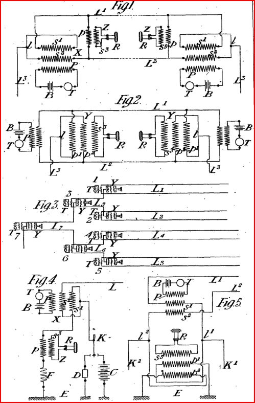
Referring first to Fig. 1 the two lines Ll L2 are at each end connected as shewn at X through two equal secondary coils 8 1 and s 2 wound with a primary coil P which is in circuit with a telephone transmitter T and local battery B.
The lines L1 L2 are so connected to the secondary coils 8 1 s 2 that the currents induced in the lines by the telephone transmitter are always in opposite directions.
The telephone receiver R, as shewn at Z, is in circuit with a secondary coil 8 3 wound with a primary coil p connecting the two lines L1 L2.
At a point l intermediate to the coils s1 s2 a third line L3 is connected, this line being employed for telephone or telegraph transmission. When either of the telephone transmitters T is employed, the induced currents pass through the primary coil p thus causing the receivers R to act. But should any current flow by L3 it must flow in opposite directions through 8 1 and s2, and therefore in the same direction along the lines L1 L2 so that it cannot influence the receivers R nor the transmitters T. At each end a line L3 may be connected as shewn by Y, Fig. 2, at l a point intermediate to two equal primary coils p1 p2 which connect the lines Ll LO and are wound with the secondary S3 of each telephone receiver R.
With connections thus arranged any current flowing in the same direction through the coils pl p 2 actuates the telephone receivers R, whereas a current from L3 flows in opposite directions through the coils pl p 2 and therefore is ineffective on the receivers R. By combining several ordinary transmitters T and several of the receiver arrangements marked Y in Fig. 2 with a number of double lines as shewn in Fig. 3, a number of messages can be sent over these lines without interfering with each other.
Thus referring to Fig. 3 the transmitter 1 works over the pair of lines L1 in the - usual way, one of these lines serving as metal return. In like manner the transmitter 2 works over the pair L2, transmitter 4 over the pair L 4 and transmitter 5 over the pair L 5. Again the transmitter 3 works through the pair of lines L 3 and the two pairs L 1 and L 2, one of these pairs serving as metal return.
In like manner the transmitter 6 works through the pair of lines L 6 and through the two pairs L 4 L 5. Finally the transmitter 7 works through the pairs of lines L 7 and through the two pairs L 3 and L 6 and the. four pairs L 1 L 2 L 4 and L 5, two of these pairs such as L 4 and L 5 serving as metal return.
Obviously this system may be duplicated, and reduplicated so that one transmitter can be made to work over 8 pairs or 16 pairs of lines or other multiple of 4.
As shewn in Fig. 4 a telephone and a telegraph are connected to one line L having earth return. In this case X and Z are the telephone arrangements so marked in Fig. 1, K is the key, C the battery and D the receiver for telegraphing in the connection of Z to earth there is an adjustable resistance F to balance that of the line. As shewn in Fig. 5 two sets of the telegraphic connections shewn in Fig. 4 and two lines Ll L2 which may be both to one place or each to a different place with earth return are combined with one telephone arrangement.
The transmitter T by its primary P induces currents in the secondaries $ 1 89 both in the same direction and therefore in opposite directions in the lines Ll L2. The currents being in the same direction in p1 and p2 act on the secondaries 1 3 of the receivers 1,. Currents from the telegraph gi dividing at 11 pass in opposite directions through sl and pl and therefore do not affect the telephonic receivers. And in like manner the currents from the telegraph K2 are ineffective on the receivers.
For the sake of clearness the primary and secondary coils have been shewn in the form of many lines side by side.
It is to be understood however that they are wound in each case all on one bobbin.
In Figs. 3,4 and 5 the arrangements are shewn at only one end of the conducting lines.
It is to be understood however that they are symmetrically repeated at the other end as shewn in Figs. 1 and 2.
COMPLETE SPECIFICATION.
This invention relates to the connecting of telephonic and telegraphic instruments to conducting lines in such a manner that several telephonic and telegraphic messages can be simultaneously transmitted without interfering with one other.
Figure 1 of the drawings accompanying my Provisional Specification shews diagrammatically connections for a telephone and also for another telephone or .telegraph to a double conducting line. Figure 2 shews a modification. Figure 3 shews how seven sets of the connections may be applied to four double conducting . lines: Figure 4 shews the connections for a telephone and telegraph to a single line with earth return. Figure 5 shews connections for telephoning over two telegraph lines one of them forming a metal return.
1 . Referring first to Figure 1 the two lines Ll L2 are at each end connected as shewn at X through two equal secondary coils s1 and 8 2 wound with a primary coil P which is in circuit with a telephone transmitter T and local battery B.
The lines Ll L 2 are so connected to the secondary coils 8 1 s'" that the currents induced in the lines by the telephone transmitter arc always in opposite directions.
The telephone receiver R, as shewn at Z, is in circuit with a secondary coil s3 wound with a primary coil p of high resistance connecting the two lines L1 L2.
At the point intermediate to the coils sr s 2 a third line L3 is connected, this line being employed for telephone or telegraph transmission. 'When either of tho telephone transmitters T is employed, the induced currents pass through tho primary coil p thus causing the receivers R to act. But should any current flow by L3 it must flow in opposite directions through sl and s2, and therefore in the same direction along the lines Ll L2 so that it cannot influence the receivers It nor the transmitters T. At each end a line L3 may be, connected as shewn by Y, Figure 2, at l a point intermediate to two equal primary coils p1 p2 which connect the lines L1 L2 and are wound with the secondary 8 3 of each telephone receiver R. With connections thus arranged any current flowing in the same direction through the coils yx actuates the telephone receivers R, whereas a current from L3 flows in opposite directions through the coils p1 p2 and therefore is ineffective on the receivers R. By combining several ordinary transmitters T and several of the receiver arrangements marked Y in Figure 2 with a number of double lines as shewn in Figure 3, a number of messages can be sent over these lines without interfering with each other.
Thus referring to Figure 3 the transmitter 1 works over the pair of lines L 1 in the usual way, one of these lines serving as metal return.. In like manner tho transmitter 2 works over the pair L 2, transmitter 4 over the pair L 4 and transmitter 5 over the pair L 5. Again the transmitter 3 works through the pair of lines L 3 and the two pairs L 1 and L 2, one of these pairs serving as metal return.
In like manner the transmitter ti works through the pair of lines JLA b and through the two pairs L 4 L 5. Finally the transmitter 7 works through the pairs of lines L 7 and through the two pairs L 3 and L 6 and the four pairs L 1 L 2 L 4 and L 5, two of these pairs such as L 4 and L 5 serving as metal return.
Obviously this system may be duplicated, and reduplicated so that) one transmitter can be made to work over 8 pairs or 16 pairs of lines or other multiple of 4.
As shewn in Figure 4 a telephone and a telegraph are connected to one line L having earth return. In this case X and Z are the telephone arrangements so marked in Figure 1, K is the key, C the battery and D the receiver for telegraphing.
In the connection of p to earth there is an adjustable resistance F to balance that of the line. As shewn in Figure 5 two sets of the telegraphic connections shewn in Figure 4 and two lines Ll L2 which may be both to one place or each to a different place with earth return are combined with one telephone arrangement.
The transmitter T by its primary P induces currents in the secondaries sl S2 both in the same direction and therefore in opposite directions in the lines L1 L2. The currents being in the same direction in pI and pS act on the secondaries i1 of the receivers It.
Currents from the telegraph K1 dividing at 1 1 pass in opposite directions through sl and I > I and therefore do not affect the telephonic receivers. And in like manner the currents from the telegraph K2 are ineffective on the receivers.
The connections of p1 and p2 to earth may have suitable resistances as shewn at F in Figure 4.
For the sake of clearness the primary and secondary coils have been shewn in the form of many lines side by side.
It is to be understood however that they are wound in each case all on one bobbin.
In Figures 3,4 and 5 the arrangements are shewn at only one end of the conducting lines.
It is to be understood however that they are symmetrically repeated at the other end as shewn in Figures 1 and 2.,
Perfectionnements
aux bobines d'induction
FR382386
1908-02-05
FR382386
The present invention relates to an improved induction coil in order to obtain induction currents in very short periods. These currents, whose durations are extremely short 5, enjoy special properties which find application mainly in telegraphy and wireless telephony.
This induction coil is characterized by the absence of the magnetic core and the winding mode of the inductor and the armature on a short length coil, but a very large diameter, the inductor coil being virtually drowned in May 1 the armature winding.
The appended drawing schematic represents for example an induction coil according to the present invention.
FIG. 1 is a section along line A-20B of FIG. 2 ;
FIG. 2 is a plan.
As shown in these drawings, this coil has a very large diameter which can be up to several meters; 26 is drawing the round, but it could equally be square or affect any other polygonal shape. This reel is very long because all winding son are housed on its outskirts in a suitable groove b; it will be understood by 3o begins winding on the rim of this kind of pulley a first layer of wire induced E and then covered with a suitable insulating and d are wound over this insulating layer the inductor wire E which is covered another 35 isolated layer; we réuuïi uêUi the insulating layers d and f, so as to isolate the inductors e and ends the coil by an external winding armature wire g. ko
Is carried out in this way a large-diameter ring compound induced son c, g, containing a central core of an adequately insulated son inductors.
The machine has four terminals 5 h which two are used to secure the ends of the armature winding and the other two ends of the inductor winding.
We can arrange several induced son and son more inductors; in this case, each terminal 5o h will be replaced by a multiple switch that will bring together the different armatures on, and the different inductors on, either voltage or the contrary in quantity, following the effects that one wishes to obtain.
Dispositif
de transmission téléphonique
FR377785
1907-09-14 FR377785
Telephone transmission system of mounting each station transmitter and or serial receivers and to bring the two stations by three son line, including 5o first two respectively together the poles of the two stations and the third is mounted derivation at a point of each station caught between the transmitters and the receiver or receivers, one or even two of these three son may be replaced by equivalent landings.
The present invention provides a way to increase the distance at which it is possible to call or to increase the intensity of sound transmitted at a given distance 5.
When installing a regular telephone line, it is customary to bring the two stations using two wires, one for the second round for the return; at-10 there is no fear induction from neighboring lines, one connecting the two stations by a thread alone and return through the ground at each station.
FIG. 1 of the accompanying drawing shows the 15 most simple provision of a regular line with two son; there is one at each station magnetic phone, a1 met by both son line c and d; when speaking in the phone, the phone is 30 a1 receiver and vice versa; this provision is entirely satisfactory from the standpoint of the actual transmission, but it has the obvious disadvantage that the two parties can not break interfere, each necessarily listen to while the other speaks .
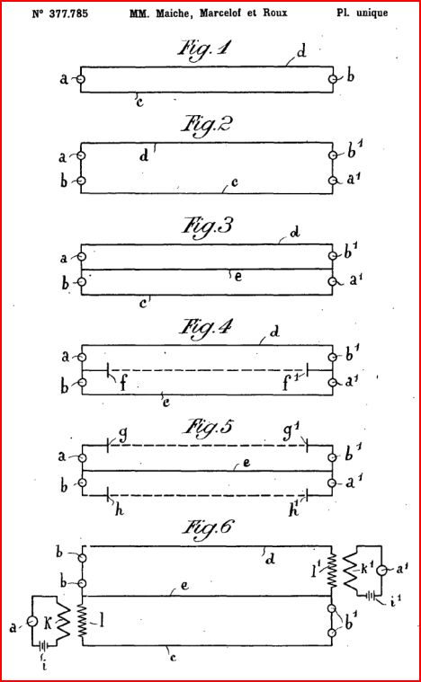
To overcome this disadvantage, it immediately offered to have each transmitter station a phone or a 1 and a receiver or telephone b bl, allowing 3 to the two interlocutors to talk while listening. This solution suffers a disadvantage from the standpoint of the transmission; in fact, as shown in Fig. 2, the four phone a, b, a}, bx 3 are mounted in series on the line cd, so that the sound transmitted by a transmitter has or a1 necessarily travels in addition interesting b1 or b receptor both other phones of the circuit. The telephone circuit thus unnecessarily h has a high resistance which reacts disadvantageously either on the possible length of the line cd, either the intensity of the sound transmitted to a given line length.
The present invention relates to a device easy positive h to remedy the drawbacks both of the two transmission systems according to Fig. 1 and 2 and make a new telephone transmission system providing both the benefits of the 5 two known systems.
As shown in Fig. 3, this invention is simply to dispose between the two stations a third e line wire terminating at each station between the telephone transmitter 5 tor a or a1 and the receiver phone b or b1. In these conditions the wall sent by "will be fully received by b1 without crossing unnecessarily b and a1 resistance and vice versa speech transmitted by a1 will be fully received by b.
The need for three son line c, d, e 5 is required when the line is around other transmissions; but when isolated, it can simplify the transmission as shown in Fig. k or 5.
According to FIG. h, the wire line drifted o-tion e is deleted and replaced by a ground f and f1 taken at each station between the transmitter and receiver.
In special cases, it is even possible to reduce the line to a single wire e in '5 with each station two landings g, h and # 1, h1), the receiver and transmitter are each disposed station in series between the two landings; under these conditions, the two conductors c and d are formed by o the ground and there is no longer a single line wire e.
In the above, to simplify the description and drawings, we assumed the exclusive use of magnetic phones; 5 Fig. 6 shows the circuit diagram in the case of induction phones. In this case each position i includes a battery, a transmitter microphone and primary k of an induction coil, mounted in series o on a closed circuit; the line circuit c, d comprises series headphones b, b and b1, b1 and side and ll of the coil. In this
If the invention is to attach the derivative e line wire between the two receivers b, b or i1, A1 on the one hand and the secondary or ll 35 on the other hand, as shown in FIG. 6.
The result of these provisions is summed up by the possibility of quadrupling of the intensity of the reception for a given length of line, or the length of the line Zio maintaining the same intensity.
Nouveau
mode de transmission sans fils des courants télégraphiques
et téléphoniques en employant comme conducteurs la terre et
l'eau
FR320267
1902-12-05FR320267
To understand our invention, it is good to remember that in an ordinary telegraph line a thread, more or less isolated, from a point to another, communicates with earth at each end. A power source; and a transmitter unit are sandwiched between the starting line and earth. Upon arrival, a receiver also communicates with the line and the earth.
We know that each of the posts supporting the line passes a small amount of power that is lost in the ground. Large amount of current is now lost all plus 1 large 5 that the distance between stations is itself larger and, consequently, the number of' poles is higher. Loss can become considerable, without preventing transmissions. It may even happen that the ao thread without being broken, drags on earth there for a certain length of son'parcours and continues to allow the current of a shift to another, albeit very weakly,
The experience proved us uninsulated conductor could even, for certain distances, be simply placed on the ground and that transmissions would nevertheless be possible.
We are able to continue, transmit signals is greatly increased if, at each end, the uninsulated wire touching the ground, met in a well-insulated wire that extends the line to a ground to the point where so are transmitters and receivers.
It is understood that the ground at the end of a secluded part forces the return current from sinking into the depths of the earth ho and that, consequently, there is an infinitely small closure point where the uninsulated wire touches the ground. In other words, the loss suffered in ground contact, the uninsulated wire, is even less than each end of uninsulated wire so is an insulated wire from the ground at a greater distance.
Hence, if the lead wire, instead of iron, consisting of a much less conductive material, coal, for example, everything would be the same way. We also recognized that even when iron, coal or other similar material, are replaced by placed water, salt if possible, and, consequently, by a stretch of sea or any other part of sea whose geographic provision lends itself to this kind of installation.
When it comes to cross an arm of the sea, the isolated line extension is placed preferably in the direction of the straight line through the two points to be connected.
In case one transmission on a role, isolated leagues will be perpendicular to the straight line joining the two stations.
Isolated lines will not be too long, and therefore, will provide not only coast to coast, but between two points inland. The thickness of the salt water layer being at even greater depths, only about the thickness of the land mass, the proportions remain between water and adequate the earth so that water plays exactly the same role that the uninsulated conductor touching the ground.
To make our evplications as clear as possible, we have shown diagram-matically, in the accompanying drawing, an installation in which our invention is applied.
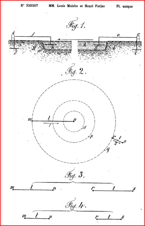
A is the sea (Fig. I) and 13 b are both shores, c and d both stations, e and f insulated, and the plates located in the water, i and it updates earth.
We see that the sea is an extension isolated son e and f, and it plays the role of an uninsulated conductor based on floor.
To make it clear how 3 o operates the propagation of electric currents, we assume an isolated line (Fig. A) within two earthed m and n. If the current is moving in the direction of the llèche, electricity arriving ashore in n flourishes spheres 3.) concentric o, p, q, etc., all points of each sphere simultaneously receiving the same amount of electricity if the propagation medium is uniform. Be grounded in r therefore receive the current along the earth m, r and if this land is connected by a line by t, s land to another, even very close to her, the current finding less resistance in the isolated line in the middle (Jun separates the two nets land, will follow this line, as shown in llèche a. It will be thus possible to establish a wireless communication between any point of the line / on which find transmitting devices, and any point on line T which will be appareds receptors.
To establish simultaneously on each of the leagues and t, a position transmitter and a receiver will require that the line is the same length as the line 1, J J as shown in Fig. 3.
If the medium is found to be twice as conductor between h and r between m and n, on the one hand, and between r and s on the other hand, the lines l and t may have as half the length of the distance between the points n and r (fig.û).
Of course, transmissions based on the principle that we have indicated, may be made by taking as con- bo different producers, not only the earth and the sea water, but the earth and air, land in this case, acting as a better conductor brought by the air; the insulated wire from the earth lead to the air at each station 7. tion to a more or less remote distance according to the distance that would take. It is obvious that the latter provision, the sea and fresh water advantageously replace the earth. 7°
In summary, we claim as our exclusive property, the new method, described above, transmission without telegraph and telephone currents, said transmission mode of making pass in a conductive medium the current emitted by the base station and to receive on arrival in this current an insulated wire of suitable length, which are sandwiched the receivers and resulting in a second medium whose specific conductivity is less than that of the first medium, but passes the total quantity of electricity because of its mass which is greater than that first medium, an insulated wire, on which the transmitting devices is also leading into the second medium, so that the first medium is an extension of two isolated lines, and the second medium acts as the return wire, the two isolated lines to be used both for shipping and for the reception.
Un
nouveau mode de transmission et de réception des courants
télégraphiques et téléphoniques sans autre conducteur que la
terre ou l'eau
FR318007
1902-10-03 FR318007
In an electrical circuit consisting of a power source and a metallic conductor whose ends are grounded, which closes the circuit, the earth acts as 5 driver not only a straight line between the two landings, but on a almost infinite extent; However, with a power density decreasing in proportion to the distance.
If parts of the ground are better conductors than others (because of the moisture, the saltiness of the water or any other cause) the current preferably passes through these parts describing curves or bends as does a river following the slopes of the terrain.
It follows that if, on part of the land used as return conductor, it artificially creates a better conductor line as the earth, it will be traversed by the current in preference to any other lower conductive part.
The effect is much more complete and can collect the current and note its existence when the best conductive line is insulated from earth and communicates with it by its ends. The current that would have crossed the land finding a wise not easier by the wire preferably follows and restores much faster electrical neutrality of the ground. It is isolated by cutting the line at any point that can be inserted in the course of the current instruments ( telegraphic or telephonic receivers) that can detect its existence.
It is understood that if the isolated artificial line is a very good conductor, if its ends are connected to metal surfaces large enough in contact with the ground, the closing of the circuit will cause the ground to be in a state of electrical neutrality absolute.
Under these conditions, if a current electric is sent intermittently in the metal line, charge the earth, for each issue, a certain amount of electricity instantaneously discharge into the isolated artificial line.
Experience has shown that these phenomena can occur even when there is almost no gap between the two landings transmitter station or between two plates that collect the color rant crossing the line isolated the receiving station, to the condition that at each station the plates which lead to the two lands are carefully insulated from each other by means of a sufficiently thick insulating separation that no induction effect or condensation on one another can occur, and fairly large compared to the dimensions of the plates to prevent current from closing on itself too close to the to start. The current is so obliged to flourish "right and left of the landings, and the point where the positive and negative electric waves begin to reach is considerably related. I can further increase the desired effect by minimizing the current closure on itself through a number of insulating walls arranged below the plates to prevent farm-i o ture of the circuit by the depth of the earth, on the side opposite that in which the transmission must be received and, if necessary, above the plates.
In general, the plates will be placed vertically on either side of an insulating wall, their smaller dimensions being turned to the opposite position.
I can also use a wide insulating tube divided in two by a thick wall normal to isolated generators. The plates will be set back to back on either side of this partition in the interior of the tube and placed in communication with the outer conductor through insulated son.
The tube may be straight, or consists of two parts forming between them an angle properly calculated so that the circuit is closed by the earth is done by almost entirely in the 3 o where the current is sent.
It is obvious that the installation is completed by transmitters and telegraph or telephone receivers that may be any, as the source of electricity.
I claim as my exclusive new property above described transmission and reception of telegraph and telephone currents without other driver as land or water, said system of separating the two landings each position by established insulating material to prevent the production of induction phenomena of condensation and the circuit closing on or by the depth of the earth, and force the air to flourish right and left, so that they can begin to get to and distant from the transmitter station, the two earthed of each position can thus without drawbacks, are moved towards one another until they fit on either side of the same insulating wall.
Nouvelle
disposition de bobine d'induction
FR647 (E)
Système de communication télégraphique et téléphonique
FR376100
1907-07-30
Mode de transmission de signaux télégraphiques
FR361733
1906-10-23
Nouveau moyen de transmission et de réception sans fil des courants électriques
FR321454
1903-01-10
Récepteur télégraphique pour toutes transmissions en général, avec ou sans fils
FR320467
1902-12-11
Nouveau récepteur des courants électriques
FR319195
1902-11-06
Nouveau moyen destiné à augmenter la sensibilité des microphones
FR319155
1902-11-06
Nouveau système de télégraphie et de téléphonie sans fil
FR318507
1902-10-17
Système de communication télégraphique et téléphonique
FR7464 (E)
1907-08-09
Dynamo - oder magnetelektrische Maschine
DE46075
1889-02-05
Transformateur téléphonique sans noyau magnétique
CH44013
1909-07-01
Wicklung von eisenfreien Transformatoren für Fernsprechzwecke.
AT40498
1910-01-10
Système de télégraphie et de téléphonie sans fil
FR392252
1908-11-21
Dispositif pour transmetteur et récepteur téléphonique
FR390346
1908-10-02