Joseph NEWMAN
Gyroscopic Magnetic Particle Motor ( II )
NEWMAN : Magnetic Particle Motor ( I )
The Energy Machine of Joseph
Newman
by Joseph Newman
by Joseph Newman

[ 1 ] [ 2 ] [ 3 ] [ 4 ] [ 5 ]

Google Images
[ Click to enlarge ]


[ Click to enlarge ]
Videos
https://www.youtube.com/watch?v=r52VWrIZui8
The
Energy Machine of Joseph Newman
https://www.youtube.com/watch?v=4cOTfqFq8i0
Joseph
Newman motor
https://www.youtube.com/watch?v=nzhSBO5MSQU
Joseph
Newman Motor replications by Geoffrey Miller

https://www.youtube.com/watch?v=O9_a3tZcVaE
Tiny
Newman Motor-Generator
This is a tiny Newman motor that has a remote pick up coil. A small ball magnet is spun up inside the pickup coil by the rotating magnet in the Newman motor. The rotating ball magnet induces a current in the pickup coil.
https://www.youtube.com/watch?v=Pm7WDU3YK5I
Improved
Joseph Newman Motor
http://video.google.com/videoplay?docid=-1610087835473512086&hl=en
http://video.google.com/videoplay?docid=3484490731703421398&hl=en
Cut
Cost of Oil 2
http://jnaudin.online.fr/html/qmmv11.htm
The
Newman's Energy Machine
by JL Naudin/M.David

by JL Naudin/M.David
http://jnaudin.online.fr/html/qm11bp.htm
Technical Specifications:
Coil Inductance = 220 Henries
Coil resistance = 17,332 ohms
Copper used = 20,440 m of AWG 34 (16/100)
Weight of copper : 3,650 gr
Magnets : 8 NIB (Bremag 27MGoe) (2x4 magnets stacked)
Magnet spec (one unit), ref: BREMAG27
diam 22mm and 10 mm thick,
BH Max : 27MG Oe 208 Kj/m3
Br : 10500 G 1050 mT
Hc : 10000 Oe 800 kA/m
Pulsed coil voltages : about 300 Volts DC ( with BackEMF spikes up to 1500 Volts..)
Speed = 230 RPM
Commutator type : Mechanical (brushes)
http://jnaudin.online.fr/html/qm11com.htm
The Commutator design and the power supply


Each pair of brushes are made with a copper or silver sheet and must be separated by at least 10mm to prevent eventual sparks.
If you want to use the Newman's motor with a 12V DC Battery, you need only to connect the 12V DC power supply (below) instead of the 220/220V insulator transformer from the main power supply (above).
http://jnaudin.online.fr/html/qm11tun.htm
The Tuning and the oscilloscope pictures

The picture above shows the voltage induced in the coil without pulse (Free run).
You can notice that the voltage induced reaches its maximum when the rotating magnet is at 90 degrees from the axis of the coil (positions 2 and 4).
You can also notice that the voltage induced is null when the rotating magnet is at 0 degrees from the axis of the coil (positions 1, 3 and 5).
The "firing pulse" (when the current is sent to the coil) timing and duration depends of your initial choice :
Case 1: The Newman's machine runs as a MOTOR. In this case, all the magnetic energy will be used for producing HIGH EFFICIENCY TORQUE.
Case 2: The Newman's machine runs as a GENERATOR. In this case, all the magnetic energy will be used for producing STRONG BackEMF which RECHARGES THE BATTERY SOURCE and also produces usable electricity.
Case 3: The Newman's machine runs as a MOTOR/GENERATOR. This is the best case, but the more sophisticated for the design and the tuning of the commutator. In this case, all the magnetic energy stored in the coil and the magnetic energy from the rotating magnet will be used for producing HIGH EFFICIENCY TORQUE and also for producing STRONG BackEMF, this RECHARGES THE BATTERY SOURCE.
The Newman's Energy Machine V1.0, that I am glad to present you, has been designed only for the case 1 and 2. The case 3 can be done with an enhanced and more sophisticated commutator.
For tuning the timing of the "firing pulse" Vs the angle of the rotating magnet you must :
1) Adjust and lock the commutator wheel, so that the "contact sheets" must be parallel with the axis of the rotating magnet,
2) The phase adjustment can be finely tuned by moving left and right the arms which maintain the pair of contacts. You need to check this with an oscilloscope connected accross the coil. Be carefull of the High Voltage, the spike can reach up to 1500 Volts, so I suggest you to add a 1 Mohms resistor in series with your scope probe (you see this resistor in the picture above),
3) The Pulse duration can also be finely tuned by moving up and down the arms with the pair of contacts. So, by this mean, you will be able to adjust the pulse duration of the "firing pulse". The closer to the circumference, the shorter will be the pulse duration.
In this case, the Newman's Machine acts as a GENERATOR (see the strong backEMF spikes)
Rotor speed : about 230 RPM, (one turn in 260 milliseconds)
Pulses duration : 30 milliseconds at 275 Volts
TWO pulses sent by turn (in opposite direction): One pulse each 180 degrees,
when the axis of the magnets are at 90 degrees from the coil axis.
Working cycle : 26% by turn
Some Tips for the tuning :
For the best tuning you need to add a 100 ohms resistor in series with the coil, so you will be able to measure the Voltage and the Current accross the coil.
If you want the Newman's machine to run as a GENERATOR you need to adjust the firing pulse, so that the commutator is opened at the points 2 and 4 (see the "Free Run" picture above). With this tuning you get very STRONG SPARKS (see the scope picture above) and you can use this BackEmf energy for recharging the capacitor/battery.
If you want the Newman's machine to run as a MOTOR you need to adjust the firing pulse, so that the commutator is opened when the CURRENT is nullified by the magnetomotive energy resulting from the BackEmf and the Rotating magnet. So the motor will "regauge" itself each 180 degrees and will be able to give its best efficiency in mechanical power.
http://jnaudin.online.fr/html/qm11pt1.htm
The preliminary tests results ( June 17, 1998 )
PRELIMINARY TEST : RUN 1 (06-17-98)
Note from Jean-Louis Naudin :
This is only a PRELIMINARY TEST of my Newman's Energy Machine 1.0, so all the measurements need to be checked and rechecked again for a better proof of the result showed bellow.
I have chosen my Newman's machine to run as a MOTOR, so the commutator was opened when the CURRENT in the coil was nullified by the magnetomotive energy resulting from the BackEmf and the rotating magnet.
PATENTS
WO8300963 / IT1209994 / IN163290 / ZA8301296 : ENERGY GENERATION SYSTEM HAVING HIGHER ENERGY OUTPUT THAN INPUT
WO2006101494 : AN EFFICIENT ENERGY PRODUCING ELECTROMAGNETIC OR MAGNETIC DEVICE
WO2006093488 : AN EFFICIENT WIND ACCELERATING AND WIND ENERGY PRODUCING DEVICE
WO8801245 : ELECTROMAGNETIC DEVICE FOR MOVING AND/OR LIFTING ABOVE THE EARTH'S SURFACE AND EFFICIENT SPACE TRAVEL
WO2008069799 : BOAT PROPULSION DEVICE
WO8300963 / IT1209994 / IN163290 / ZA8301296
ENERGY GENERATION SYSTEM HAVING HIGHER ENERGY OUTPUT THAN INPUT
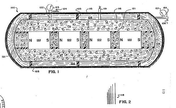
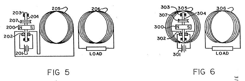
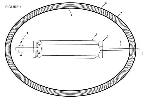
A system for generating obvious work motion, or electromagnetic energy (fields of force) or electric current utilizing the electromagnetic energy which makes up a matter and results in a greater output of energy, than the initial input of conventional energy means and teachings. A first exemplary embodiment (Figure 1) of the generator uses a contained fluid (117) surrounding a series of aligned magnets (120); while a second exemplary embodiment (Figure 3) uses a special material (201) held stationary between two static magnets (202, 203), the special material having its atoms aligned but maintaining the resulting magnetic field at least substantially within its boundary surface; while third and fourth exemplary embodiments (Figures 5 and 6) utilize a relatively heavy coil (205) made up of relatively large diameter wire of relatively great length and number of loops and length and a relatively small energizing current to drive a rotatable permanent magnet (200).
1. Field of the Invention:
The present invention relates generally to devices or systems (including methods) for generating useable energy such as for example electrical energy from electromagnetic fields, electrical energy or electromagnetic fields from matter, and more particularly to devices or systems (including methods) for producing electrical current flow for use as electrical power, and magnetic fields of force which cause motion (obvious work) or electrical current flow or for increasing electromagnetic potential energy available for use or mechanical energy available for use.
2. Prior Art:
There have been many devices proposed over the years for producing electrical -energy, with mechanical friction, thermo-electricity, photoelectricity, piezoelectricity, electrochemisty and electromagnetic induction being the chief forms of primary energy capable of producing electricity. Of these, the only significant source of commercial electrical power has been the mechanical actions of electric generators, and for mobile electric power the chemical action of batteries has been important. Usable motion has resulted from the interactions between the input of electrical energy and the magnetic and/or electromagnetic fields of force (electric motors) and heat or light as a result of input of electrical current through conventional mechanical systems, heaters, light bulbs, etc.
All of the prior art systems are designed accordingly to rigid mathematical laws taught both in physics and electrical engineering which coincide with the hypothesis rigidly accepted by the industrial and scientific communities concerning the Second Law of Thermodynamics (1850).
From the foregoing generally accepted hypothesis it has also been generally accepted and rigidly taught in physics and electrical engineering that the electric current flowing in a closed circuit from a battery, electric generator, etc.
is used up in the mechanical device being operated by this flow of electric current, and that all such electric current producing systems would only put out at most work equal to the work initially put into the system, or in accordance with generally accepted laws stating that a particular electrical generating system was only capable of a given output of energy and no more.
These beliefs have till this date still remained rigid in both the industrial and scientific communities in spite of proof of Einstein's equation of 2 Nuclear reactors convert matter into usable electromagnetic energy in the form of heat, which converts water into steam to turn conventional turbines for production of electric current by conventional electrical generating means. This system is extremely inefficient using less than 1% of the energy of the atom and producing a deluge of contaminated materials which has caused a serious problem as to safe disposal.
Additionally, the basic electrical generators is use throughout the world today utilize the principle of causing relative movement between an electrical conductor (for example a rotor) and a magnetic field produced by a magnet or an electromagnet (for example a stator), all using the generally accepted hypothesis that the greater the relative speed or movement between the two are concerned and the more normal or perpendicular the relative movement of the conductive material to the lines of force of the electromagnetic field, the greater will be the efficiency of the prior art electrical generator. Additionally, all of the prior art systems are based on the generally accepted hypothesis that the greater the electrical conductivity of the material being moved through the field, the more efficient will be the electrical generation.
From the foregoing generally accepted hypotheses, it also has been generally accepted that there should always be movement between, for example, the rotor and stator elements, and that only generally accepted electrical conductors, that is materials with high electrical conductivity, will effectively serve in an electrical generation system.
However, in one of the systems (Figure 3) of the present invention, electrical generation can occur with relatively static elements and with materials that are not generally considered to be of high electrical conductivity, although, of course, the present invention likewise can utilize relatively moving elements as well as materials of generally accepted high electrical conductivity, if so desired, as occurs in the systems of the present invention illustrated in Figures 5 and 6.
The prior art has failed to understand certain physical aspects of matter and the makeup of electromagnetic fields, which failure is corrected by the present invention.
BRIEF DESCRIPTION OF DRAWINGS:
For a further understanding of the nature and objects of the present invention, reference should be had to the following detailed description, taken in conjunction with the accompanying drawings, in which like parts are given like reference numerals and wherein:
Figure 1 is a schematic, side view in generalized, representational form of a first embodiment of an electrical generator based on the principles and guidelines of the present invention.
Figure 2 is a close-up view in general form of an electrical charge pick-up element which can be used in the generator illustrated in Figure 1.
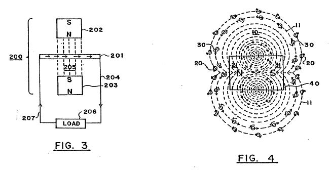
Figure 3 is a schematic view in generalized, representational form of a second embodiment of an electrical generator based on the principles and guidelines of the present invention.
Figure 4 is a schematic view in generalized, representational form of the negative and positive particles exhibiting gyroscopic actions which emanate from a magnet to form an electromagnetic field.
Figures 5 and 6 are schematic views in generalized, representational form of third and fourth embodiments of a combined electrical generator and motor utilizing a static, relatively large coil energized by a relatively low current driving a rotatable magnet, wherein in the embodiment of Figure 5 the rotatable magnet is positioned along side of the coil and in the embodiment of Figure 6 the rotatable magnet is positioned within the open core of the coil.
DETAILED DESCRIPTION OF PREFERRED EMBODIMENTS:
Basic Principles and Guidelines
In accordance with the principles of the present invention and as generally illustrated in Figure 3, an electromagnetic field 10 comprises flows of quanta or particles 20, 30 of electrical energy flowing from each of the poles 21, 31 of a magnet (or electromagnet) 40 to the other pole, following the "lines of force" 11 of the electromagnetic field. These particles 20, 30, believed to be traveling at the speed of light, are always coming out of one end 21, 31, respectively, of the magnet 40 and going into the other pole 31, 21, respectively, flowing from a relatively high energy source to a low energy source.
These particles 20, 30 are, it is believed, negative and positive charges and have a spin producing a gyroscopic motion and follow the mechanical laws of gyroscopic action.
The mass of each of the particles 20, 30 equals the energy of the particle divided by the speed of light squared. The peripheral speed of the gyroscopic spin of the particles is believed to be the speed of light.
For purposes of illustration only and as a matter of nomenclature, the positive charge particle 20 is going in one direction (''N" to "S") with a clockwise spin, and the negative charge particle 30 is going in the opposite direction with a counter-clockwise spin. Of course, if a particle such as 20 or 30 is flipped around one-hundred-and-eighty degrees, it becomes the opposite charge or type of particle.
The electromagnetic field 10 is thus the orderly flow of the positive and negative charges 20, 30 moving at the speed of light from the north and south poles 21, 31, to the south and north poles 31, 21, respectively, and follow the paths of what is termed in the art as the "lines of force" 11 of the electromagnetic field 10.
As is known from the laws of gyroscopes, a gyroscopic particle or body moves at right angles to the direction of an applied force. Therefore, when a force is applied to the electrical energy particles 20, 30, they will move at right angles to that force.
It should also be noted from known gyroscopic laws that the electrical energy particles 20, 30, when they move with their gyroscopic axis straight into an object, tend to knock that object straight, but, if that object hits the particles at an angle to the axis other than at zero or one-hundred-and-eighty degrees, the particles are moved off at an angle from the straight.
Additionally, it is noted that a magnetic field caused by a current flowing through a wire comes from negative and positive particles, such as 20, 30, with a net flow of such particles going in the same direction but with opposite spin.
In the system and method of the present invention, the foregoing principles serve as guidelines in the present invention.
Reference is further had to pages DD23 thru DD27 of the Disclosure Document and to page 8, line 26 through page 11, line 23 of the prior application Serial number 25,907 and its Figures 7 - 10.
From the foregoing disclosures, many different devices, structures, and methods are possible to embody the principles and guidelines of the system of the present invention, which will in general utilize a material or substance or structure to place a force at the proper angle to the gyroscopic particles 20, 30 wherein the particles 20, 30 follow a path or paths which do not cancel one another out, thereby producing electrical current at appropriate outputs for further use or for increasing available potential electrical energy for ultimate use.
First Embodiment (Figure 1)
One possible, exemplary embodiment using the principles of the system of the present invention is schematically shown in the generalized illustration of Figure 1.
As illustrated in Figure 1, there is provided an electrical current generator 100 comprising an outer keeper housing 115 and an inner, pressure containing, closed housing 116 supported therein by insulating supports 105. A vacuum exists in the area 106 between the two housings 115, 116, which vacuum is regulated and induced by means of the vacuum line 104 with its gauge 107 and its control valve 108. The outer housing 115 acts as a keeper for magnetic fields of force, and can be made for example of soft iron, while the vacuum in area 106 prevents the leakage or discharge of static electrical charges which might build up on the exterior of the inner housing 116.
A gas or gas-liquid mixture 117 which may also include solid particles such as for example lead or brass filings, is included within the inner housing 116 surrounding a series of aligned magnets 120 carried by insulating braces or supports 121 and producing a high, combined electromagnetic field. The magnets 120, which can for example be cryogenic magnets, have their "north" and "south" poles aligned (as illustrated by the "Ns" and "Ss") so that their magnetic fields reinforce one another.
The level of the gas or gas-liquid mixture 117 in the housing 116 is regulated by means of the line 122 with its gauge 123 and control valve 124. Electric current output wires 119 are provided and extend down to electrically connect with a wire pick-up system 118 (shown in close-up in Figure 2), which can be for example in the form of very small wires forming a closely spaced network or mesh or of a porous -conducting metal body or sheet, located in and extended throughout the fluid 117 in the housing 116.
It is noted that a thimbleful of gas contains a fantastically large number of extremely tiny bodies which are in continuous, random motion moving at extremely high speeds. Hence, the fluid 117 continuously applies a force to the gyroscopic particles (analogous to particles 20, 30 of Figure 3) moving at the speed of light ' in the high electromagnetic field (produced by the magnets 120) as they continuously collide with each other, which results in the fluid 117 becoming electrically charged. The charged fluid 117 discharges its electrical charge to the pick-up wire network 118 positioned in the fluid, and the electric current .so produced and generated is taken off for use via the electrical output wires 119.
As an alternative to having internally contained magnets 120, the electromagnetic field needed in the fluid 117 could be produced by a source located outside of the confines of the fluid 117 as long as a significant field was produced within the fluid 117.
Second Embodiment (Figure 3)
A further exemplary, generalized embodiment utilizing the principles of the system of the present invention is shown in schematic form in Figure 3.
The electrical current generator 200 of Figure 3 comprises an extended member 201 of a special material having its atoms especially aligned to produce electric current when positioned in an electromagnetic field but which does not on its own exhibit any substantial magnetic field outside of its boundary surfaces but substantially contains the field within itself. This is in contrast to "magnetic" materials which likewise have atom alignment but which also exhibit or produce a substantial magnetic field in the area surrounding it.
The generator 200 further comprises for example two magnets 202, 203, with their north and south poles facing each other, with the member 201 positioned between them, and with the three elements 201-203 held static with respect to each other. Because of the special nature of the material of the member 201 and its special atom alignment, it will produce a direct current through output line 204 as a result of the gyroscopic actions of the particles of the electro magnetic field 205 produced by the facing magnets 202, 203, on the especially aligned atoms in member 201, which phenomenon occurs even when and even though the member 201 is completely static with respect to the magnets 212, 203.
However, it may be desirable in some applications to allow or produce some relative movement between the generator elements 201-203.
The output line 204 extends to an appropriate "load" 206 for using the electrical current generated by the generator 200. A return line 207 completes the circuit back to the member 201.
Based on experiments to date, it is believed that brass and lead are materials which can have their atoms especially aligned to interact with the gyroscopic particles (analogous to particles 20, 30) flowing between the magnets 202, 203 and will substantially contain within their surface boundaries the magnetic field produced by the aligned atoms or molecules.
With respect to producing the proper material with atom alignment for the member 201, it is noted that most materials seem to align their atoms in random directions when formed by conventional methods of production. However, it can be observed that certain materials can be made magnetic by putting the material in an electromagnetic field while cooling from a temperature of around a thousand degrees Centigrade. The magnetism is the result of atom alignment of the material in a given direction (see pages DD19 thru DD21 of the Disclosure Document.) All materials are affected so as to align parallel or across lines of force when in a powerful electromagnetic-field. Accordingly, if a material while being formed is cooled in an extremely powerful electromagnetic field, the atoms of the material will take a particular alignment.The atom alignment direction could be varied depending on whether the electromagnetic field was aligned with the material or at a ninety degree angle to the material. This would result in the atoms of a material having their particular electromagnetic spin direction primarily along the same axis.
However, merely having atom alignment is not sufficient. Additionally the material for the invention should be such that it exhibits very little if any magnetic field in the area surrounding it. Thus it should be noted that the exterior electromagnetic field that occurs from the atom alignment of the conventional magnet is not duplicated in the material of the invention, because the electromagnetic energy resulting from atom alignment in the material of the invention will be primarily contained within the boundaries of the material It is believed that lead, made superconductive by emersion in a bath of for example liquid helium, is such a special material and could for example serve as the material for member 201.
This then results in having a material which would place a force at the proper angle on the gyroscopic type particles moving in the electromagnetic field so as to cause an EMF to be produced even when the material was sitting still. (See also first paragraph of page DD23 and paragraphs four, A through E, of page DDl9 of the Disclosure Document.)
It is believed that high, contained pressures, ~s well as other methods, can also probably produce atom alignment as the atoms of a conductor or any material will react to sufficient external force. (See first paragraph of page DD35 of the Disclosure Document.) This possibility is also indicated by the fact that hard knocks or impacts will demagnet:ize a magnet.
The proper procedure of material production in achieving atom alignment with internally contained fields of force will cause the controlled release of electrical energy in electromagnetic fields of force when the material of the invention is placed in the lines of force of the electromagnetic field.
Third and Fourth Embodiments (Figures 5 and 6)
A. Related Principles
1. Numerous scientific tests and experiments made by the inventor indicate that the magnetic field resulting from an electrical current flowing through a conductor is the result of atom alignment within that conductor at an extremely fast speed with an ability to reverse atom alignment just as rapidly without the magnetic hysteresis associated with conventional materials considered "magnetic." Prior to this time it has been believed and taught by the scientific community that the magnetic field associated with an electric current carrying conductor was the result of the electric current itself and not of the conductor material, for example copper, which was considered to be "nonmagnetic."
Even the inventor was influenced and mislead by these teachings and attempted to mechanically explain and justify the prior teachings, as is seen on page DD-27 of the Disclosure Document which is an important part of this patent application.
However, as taught in the present invention, what mechanically happens is that the gyroscopic particles making up the electric current moving in a conductor interact with the electromagnetic makeup of the atoms of the conductor, causing them to align extremely rapidly, thereby then releasing some of their electromagnetic make-up in the form of a magnetic field exactly as explained in great detail for conventional magnetic materials in the Disclosure Document.
This is easily proven and understood by taking for example a size "14" guage conductor one foot long, winding it into a coil and connecting the coil to a meter and a 1.5 volt battery. The total current registered on the meter will be 1.5 volts and the strength of the magnetic field created from the short conductor will be extremely small. Next, the same type of test is run again but with the length of the conductor increased to for example two thousand feet, but still in a coil.The total current registered on the meter will now be considerably less, but the strength of the magnetic field given off from the conductor will now be extremely large!
This shows that the magnetic field is not from the electric current flow, but is the result of the interactions of the gyroscopic particles which make up the electric current interacting with the atoms of the conductor! This causes the gyroscopic particles of the electric current not to be able to make the circuit back to the battery so quickly, and therefore the meter shows less current used.
The magnetic field is the result of the atom alignment of the conductor. The more atoms in a conductor (up to a point), the stronger the magnetic field produced from a given amount of electric current input. Again, this is proven by changing the diameter of the conducting wires, and, with the lengths being the same, the strongest magnetic field will result from the conductor with the largest diameter. The reason for this is that there are more conducting atoms to interact with the gyroscopic particles of the electric current moving through the conductor, which results in a greater number of conducting atoms being aligned, thereby then releasing some of their electromagnetic make-up, exactly as has been explained in great detail in the Disclosure Document as being possible for all matter.
If the magnetic field produced was strictly based on the amount of current going through a conductor, as taught in the prior art, then the strongest magnetic field would result when current went through a large diameter and short length conductor, because the current flow through the entire circuit is greatest at that time. However, experiments prove that the shorter a conductor is made, the greater the current flow through the entire circuit and the less strength of the magnetic field surrounding that conductor. The longer that same conductor is made (up to a point), the greater the magnetic field surrounding the total mass of the conductor and the less current that makes the complete circuit of the entire system. Reason: more atoms!
2.Numerous scientific tests and experiments made by the inventor also indicate that the magnetic field created when an electric current moves in a conductor does not use up measurable energy when performing obvious or unobvious work, force or power. This is true no matter how strong or how immense the power of the motor or electromagnets is.
Reason: the magnetic field coming from the conductor is the result of extremely quick atom alignment within that conductor. Therefore the energy in the magnetic field is the energy that makes up the atoms of the conductor! This energy is litterally Einstein's equation of E=MC2, and therefore the energy-is believed to be moving at the speed of light.
This energy use cannot be measured by today's measuring instruments. This has been explained in great detail in the Disclosure Document and is believed to be true of all matter!
3. The same is true for the electric current that comes from a conventional battery. The electromagnetic energy coming from the battery is the energy that makes up the atoms of the material of the battery! Again this energy use is not measurable by today's measuring instruments. Electric meters of all types are simply mechanical devices which measure the amount of electric current that comes into that instrument. They do not measure the amount of mass that has been converted into electromagnetic energy.
Present teachings in science state that the electric energy flowing from a battery is used up in the device operated by that flow of electric current. This is not true at all! The electromagnetic energy released from the atom make-up of a battery has a relatively infinite capacity to do obvious work, force, or power.
This is easily proven even with a small motor and a 1.5 volt battery. With a battery connected to motor to operate it and with a meter to take readings, the motor is then physically stopped from turning by physically holding or restraining the shaft. At that moment the motor is performing no obvious work, force or power, but the meter will register a greater flow of current. The magnets of the motor can be taken out and the reading will still be the same. If the electric current was being used to operate the motor, the meter would register more current when the motor was running.
The electric current not only will operate the motor but, once it flows through the complete circuit back to the battery, it also does additional work based on Faraday's Laws of Electrolysis within the battery itself. What has happened is that the electromagnetic energy released from the atoms of the material of the battery once they have completed the circuit, then take a "short cut" and move large pieces of the mass of one material of the battery over to the other material of the battery. The inventor has stated and shown throughout the Disclosure Document that the effect of gravity was the unobvious effect of electromagnetic energy. Once the materials of the battery have combined, the extreme desire for the two materials to merge is physically reduced.These materials will attempt this merger anyway possible and, if the electric current initially released from a battery is not allowed by mechanical means to complete the circuit back within itself, the electromagnetic energy then in the mechanical means will perpetually (in a relative, theoretical sense) perform obvious work, force or power. The reason: the force which initiated this flow of current (electromagnetic make-up of atoms of material) is constant, similar to hydraulic pressure, with the noticeable exception that it is moving it is believed at the speed of light and will interact with the electromagnetic make-up of the atoms of other materials, causing them to release some of their electromagnetic make-up in the form of a magnetic field.This then multiples the capacity for doing obvious or unobvious work, force or power, which can then react with another conducting coil or with the electromagnetic energy within the magnetic field of a conventional magnet and multiply this effect even further, and on and on and on for a relatively unlimited source of energy.
The same is true in not letting the current get back to a conventional generator. If a mechanical means is set up so that the electric current is "trapped," without completing a circuit, the gyroscopic particles of the current have a capacity for continuous work without increasing the power input into the generator system. However, if the circuit is complete and the electric current moving in the system does absolutely no obvious work, power or force, the gyroscopic particles making up the current on getting back to the generator will then increase the need for more power input into the system. Reason: the opposing effect of magnetic fields as defined in Lentz-'s Law. This law is simply an observation of this effect, which before now has never been fully understood.
4. Numerous scientific tests and experiments made by the inventor also indicate that there is a correlation between the electromagnetic spin orientation of the atoms of nonconductors, semi-conductors, and conductors, and the varying results achieved with an electric current in attempting to move through these materials, or when moving these materials through a magnetic field attempting to induce electric current.
The property of resistance to electric current movement is generally speaking the same type factor already explained above for electric current producing a magnetic field when moving in a conductor.
The gyroscopic particles in a moving electric current interact with the atoms of the material through which the current is moving. Each atom can efficiently only interact with sun exact maximum amount of electric current, and, if exceeded, there is an interruption of orderly movement. Then the angle of release of the gyroscopic particles from the atoms are such that the electromagnetic release from those atoms are in the form of heat, exactly as explained in great detail in the Disclosure Document. This effect is easily observed by the fact that resistance decreases relative to an increase of the cross-section of the material. Reason: simply, more atoms within that given area, and, for a fixed input of electric current, there are more atoms to receive and interact efficiently with the gyroparticles making up the electric current.
Again the same is true for resistors designed for deliberately producing heat. Such resistors are not materials which are considered good conductors of electric current. It is stated and shown in great detail in the Disclosure Document that the electromagnetic spin orientation of the atoms of a nonconductor are different from that of conductor atoms, and therefore different results will occur from the same inputs of electromagnetic energy.
This is easily seen by the fact that, in a resistor, for a given amount of electric current input, the heat release increases as the diameter increases. What that means is that the property of resistance has decreased. On a conductor it is just the opposite. If the diameter is increased the resistance is decreased, but so is heat release. Again, this is an indication that the gyroparticles in the electric current movement interact with each atom of the material.
This same effect shows up again in conventional electrical induction from a conductor interacting with a magnetic field.
Experiments by the inventor have indicated that the property of conventional induction is the result of the same property of resistance.
If one increases the diameter of a conductor, lengths staying the same, one decreases the amount of electric current produced relative to the total number of atoms within the conductors under consideration. Or, if one takes a given number- of wires of the same diameter and length, and moves a magnet across them, the current produced will be considerably less, than if one takes the same diameter wire, but only one wire, and increases its length considerably and then forms it into a coil forming the same number of wires on any one side and then moves the same magnet across only one side of that coil, the electric current generated will then be considerably greater. Reason: the property of resistance. This is the mechanical effect within the gyroscopic electromagnetic make-up and orientation of the atoms of all materials which have the mechanical ability to perform a given task efficiently up to a point concerning input of additional electromagnetic energy and then mechanically causes varying results once this threshold is exceeded.
This and all the other thoughts and innovations in this and the previous disclosures of the previous applications and the Disclosure Document previously put forth show that there are many different mechanical ways to release a relatively unlimited source of energy from electromagnetic energy which makes up all matter and which results from this invention.
B. Working Prototypes
Figures 5 and 6 illustrate rough, working prototypes of this aspect of the invention. These embodiments are only relatively inefficient prototypes built by hand for the purpose of demonstrating the invention. It should be self-evident that the prototypes by various mechanical means and designs can easily be made extremely efficient, and the illustrated embodiments are being presented only for general, representational purposes.
As is illustrated in Figure 5, there is provided a combined electrical current generator and an electromagnetic motor comprising a rotatably mounted, permanent magnet 200, a battery 201, brushes and commutator 202, bearings 203 and power, mounting shaft 204, and a first, primary, magnetic producing coil 205 and a second, secondary electric producing coil 206. The two coils 205, 206 are juxtaposed together in parallel disposition with concurrent core center-lines, with the magnet 200 positioned alongside of coil 205 at or near its core center-line with the rotational axis of the shaft 204 positioned orthagonally to the center-line.
In the prototypes a very small battery 201, for example size "N", of 1.5 volts is used.
When the circuit is completed, the battery 201 converts an immeasurable amount of its mass into electrical current (gyroscopic particles moving at the speed of light) which goes out through the communicator and brushes 202, and then enters magnetic producing - conductor coil 205 made for example from - insulated number "14" or "15" gauge copper wire, with the total weight of the coil 205 being for example seventy to ninety pounds. This causes the atoms of coil 205 to align extremely fast then releasing some of their electromagnetic make-up (gyroscopic particles) in the form of a magnetic field. This field then interacts with the gyroscopic particles making up the magnetic field coming from the atoms of the material of the permanent magnet 200.
This causes magnet 200 to attempt to align its magnetic field movement with the magnetic field movement coming from the atoms of coil 205, resulting in rotation of magnet 200 and the shaft 204 to which it is attached. This then changes the position of the communtator and brushes 202 relative to each other's initial positions, which then causes the electric current coming from battery 201 to be going in the opposite direction into coil 205, causing the atoms of coil 205 to extremely quickly reverse their alignment and the polarity of their magnetic field which they are emitting.
The reversed field then interacts again with the magnetic field of permanent magnet 200, causing it to further rotate.
This process is then continuously repeated producing continuous rotation of the shaft 204 which can be used as a source of motive power in many different ways. A power belt wheel 207 for example using a continuous "V" belt is illustrated as a general representation of this motive power source for producing useful, obvious work. In a prototype test run with a small 1.5 volt, type "N" battery, the shaft 204 and the magnet 200 - rotated at a high speed for approximately twelve hours before running down. By improving the particular design features of the prototype and by using longer lasting batteries, the rotation time of the shaft 204 can be greatly increased to a theoretical point approaching "perpetual" for all practical purposes.At the same time the alternating magnetic field produced by the coil 205 induces into coil 206 electrical induction, which then causes coil 206 to produce an alternating current across its "load," which current can be made to exceed the conventional output of the battery 201. As needed the battery source 201 can be replaced.
It is very important to understand that, the longer the length of the conducting wire in coil 205, the stronger will be the magnetic field produced and the less electric current that will complete the circuit and get back into the battery and destroy the mechanical source of the electrical current.
This effect can be increased further by increasing the diameter of the conducting wire in coil 205 and then greatly increasing its length still further in the coil.
Reason: The gyroscopic particles making up the electric current interact with the atoms of coil 205. The more atoms in coil 205, relative to length, the longer it takes the gyroparticles of the electric current to influence them and get out the other end of the coil. It is then easily seen that, if the direction of the current into coil 205 is then reversed, this then further increases this lag time. Reason:
The gyroscopic particles have inertia and are believed to be moving at the speed of light and are interacting with the gyroscopic particles making up the atoms of conducting coil 205. These atoms also have inertia and, when the direction of current is reversed into coil 205, the incoming current then collides with the current already in coil 205 going in opposite directions.
This causes a brief hesitation during the time the current already in the coil is being forced to reverse its direction, thereby then reversing the direction of the atoms within coil 205 which have already been influenced to become aligned. This causes a constant force throughout the circuit, but does not allow very much current to get back into the battery 201 to destroy the mechanical means which initiated the release of electric current in the first place.
Therefore, it should be further understood that, the faster the current direction reverses into the coil 205, the more efficiently the matter of battery 201 is converted into 2 pure electrical energy (E=MC ), without destruction of the mechanical situation that initiates the electrical current release.
It is also important to understand that, the stronger the magnetic field coming from the mass of magnet 200, the greater will be its rotational speed . Additionally, the greater the magnetic field coming from the mass of coil 205, the greater will be the rotational speed of magnet 200, and, up to a point, the greater the electric current input from battery 201, the greater the rotational speed of magnet 200.
Reason: the greater the electric current flow into coil 205, the greater will be the percentage of the atoms making up coil 205 that are aligned. This probably has the same relationship as does achieving atom alignment in conventional magnetic materials. Once complete atom alignment is reached in coil 205, no amount of current will cause those atoms to increase the strength of the magnetic field emitting from those atoms.
Therefore, it should be clear that, for a given input of electric current from battery 201, the most efficient design is one in which the most atoms of coil 205 are influenced to atom alignment by that given electric current, which means increasing the diameter and the length of the conducting wire of coil 205 to the point that the strength of the magnetic field produced is sufficient to cause rotation of the magnet 200 to a speed that allows none or at least very little of the electric current which initially comes from the battery 201 to complete the circuit and get back into battery 201 and destroy or reduce the mechanical effect which induced the conversion of the matter of battery 201 in electric current in the first place.
Again this desired effect can be increased by increasing the strength of the magnetic field given off by the atoms of the permanent magnet 200.
In the second prototype embodiment of Figure 6, the structure and operation of the prototype is substantially identical to that of Figure 5 with the major exception being that the magnet 300/shaft 304 elements (and related sub-elements 302, 303 and 307) are positioned inside of and within the core of the primary coil 305, as compared to the placement of the magnet 200/shaft 204 elements next to and along side of the coil 205 of Figure 5. Therefore, for brevity purposes, a detailed description of the elements of
Figure 6 will not be repeated, but it is noted that the corresponding and analogous elements and sub-elements are similarly numbered in Figures 5 and 6.
It is also important to again stress the fact that the prototype designs shown are presented simply to prove the correctness of the invention, and it should be clear that the invention can be made extremely more efficient by utilizing all of the magnetic field produced by coil 205 and designing the magnet 200 of a shape and strength that efficiently interacts with the majority of the magnetic fields from coil 205. The illustrated prototypes is relatively highly inefficient in this regard, but even so, the results of the invention itself greatly exceed the prior art as to use of electric current from whatever source and interaction with an electric motor or whatever work was conventionally performed.
The applicant feels it is very important to again stress, in building many varying designs of this invention, consideration must be given to the fact that the Energy in the field of force of any type magnet is the Energy that makes up the Atoms of the material from which it comes! This Energy is a real Entity with, it is believed, a gyroscopic action. It is literally Einstein's Equation of E=MC2. And it is believed that this Energy moves at the speed of light and makes up all Matter. And that this Energy has a constant pressure effect back to the Atoms of the material from which it came, similar to hydraulic pressure.
This effect is additionally more fully understood by stating the following results obtained from experimentation by the applicant in the process of this invention.
a) When the system is initially attached to a 1.5 volt size N Battery 201 or 301 and the magnet 200 or 300 and related rotation entities are placed close to or in the center of coil 205 or 305, the following results are observed:
If the electric current produced in coil 206 (306) is then fed back into coil 205 (305) in accordance with proper polarity, the rotation speed of magnet 200 or 300 will then accelerate. If fed back into coil 205 (305) in wrong polarity, the rotation speed of magnet 200 (300) will slow down.
This proves that the total force from coil 205 (305) interacting with the magnet 200 (300) is greater when the electrical energy from coil 206 (306) is fed back into coil 205 (305), then when only the initial electric energy from battery 201 (301) is fed into coil 205 (305)!
When two or three batteries are electrically connected together in series, so as to create for example three or four and one-half volts of electrical input, this effect is multiplied. Remember, up to a point, the greater the electrical input, the greater the percentage of atom alignment within coil 205 (305).
This further proves that the electric current produced in coil 206 (306) is a result of the gyroscopic particles of Energy released from the magnetic fields which came from the Electromagnetic make-up of the atoms of coil 205 (305), and is not part of the initial Electrical Energy released from the atoms making up the materials of battery 201 (301)! The coil 206 (306) can be taken out of the system, or its electrical current fed away from the system, and the rotational speed of the magnet 200 (300) will not observably change.However, the rotational speed of magnet 200 (300) will noticeably change when the electric current from coil 206 (306) is fed back into coil 205 (305)!
Now a different result:
b) When the electric current from battery 201 (301) becomes weaker to the point that the magnetic field coming from coil 205 (305) has weakened and shrunk allowing the magnetic field of the rotating magnet 200 (300) to expand and then noticeably induce electric current into coil 206 (306) and into coil 205 (305), then reverse results are observed. When the magnetic field from the coil 205 (305) is large, then the magnetice field from magnet 200 (300) is retained!
If coil 206 (306) is then short circuited, the rotation of magnet 200 (300) will noticeably slow down.
If electric current from coil 206 (306) is fed back into coil 205 (305) in wrong polarity, the rotation of the magnet 200 (300) will stop. If fed back into coil 205 (305) in correct polarity, the rotation of the magnet 200 (300) will slow down. At that point, the rotation of the magnet 200 (300) will not accelerate, no matter how connected!
These results show that, at this time, the magnetic field from magnet 200 (300) noticeably induces a current in coils 206 (306) and 205 (305) which opposes the rotation of the magnet 200 (300). This effect has already been mechanically explained, and it has been shown that Lenz' Law was simply an observation of that mechanical explanation.
These results further demonstrate that the expanding and collapsing magnetic fields from coil 205 (305) and 206 (306) do not noticeably effect each other detrimentally.
Because the resulting magnetic fields from all the coils are the results of fluctuating atom alignemnt within the coils!
Remember, the gyroscopic energy particles making up the magnetic fields have a hydraulic pressure effect back to the atoms from which they came. Also remember that the atoms making up the material of the permanent magnet 200 (300) are stationary as to atom aligment direction! Therefore, the pressure effect resulting from an opposing field which the magnet 200 (300) induced, is immediate. As is Hydraulic Pressure.
However, the magnetic field emitted from the atoms of coil 205 (305) relative to induction into the atoms of coil 206 (306) are flucuating and out of step, so to speak, and therefore, in harmony with each other. The pressure effect from the induction of coil 205 (305) into coil 206 (306) is an action and reaction effect which reinforces the flipping action of the atoms of coil 205 (305) and back into the atoms of coil 206 (306).
This action is again seen when the invention is hooked into one-hundred-fifteen volt alternating current, and battery 201 (301) is not used.
The magnet 200 (300) will not rotate even though the magnetic field from coil- 205 (305) is strong and is alternating. Reason: The fluctuating magnetic field is so fast, that the inertia mass of magnet 200 (300) can not get started in one direction before the magnetic field from coil 205 (306) has reversed, thereby, causing magnet 200 (300) to only microscopically vibrate at sixty cycles per second.
And, if a sixty watt bulb is hooked into the system of coil 205 (306), it will only dimly light. And there is a lag time of two to three seconds before it lights even dimly.
If then coil 206 (306) is hooked to a meter, there is a reading of forty-nine volts, and if the meter is replaced by another sixty watt bulb it will only extremely dimly light.
However, the sixty watt bulb hooked to coil 205 (305) will now noticeably-become brighter! This again shows that the action and reaction results of the atoms of the coils are not noticeably detrimental to each other. Because of the lag time (out of step, so to speak), resulting in reinforcing the flipping atom alignment of the coils.
From this further explanation of the invention it is seen that desirable results may be obtained by the following:
For example, in Figure 6 the magnet 300 may be of a design and/or be located at a distance from the inside diameter of coil 305 and coil 306, whereby the majority of the magnetic field from the magnet 300 do not cut the conducting loops of coil 305 or 306. Yet the alternating magnetic field produced by coil 305 should efficiently have the majority of its gyroscopic particles interacting with the majority of the gyroscopic particles making up the magnetic field of the permanent magnet 300. But not directly reacting with the atoms making up coil 305, or magnet 300!
When the magnetic lines of force of the magnet 200 (300) cross at right angles with the conducting wires of coil 205 (305), 206 (306), a braking action is incurred.It should be noted that, as the inner diameter of coil 205 (305) increases, the percentage of time of braking effect decreases.
Along this same line of instruction, the commutator segments 202 (302) can be made of a large diameter and the area of brushes made small, whereby, when the brushes cross over the gaps in the commutator segments, there will be no short circuit at any time directly back to the battery 201 (301).
By combining the slip rings and brushes (the slip rings can be made of a small diameter) to the side or sides of the brushes and commutator segments 202 (302), then battery 201 (301) does not have to rotate with magnet 200 (300).
The No. "14" and No. "15" gauge copper insulated wire of seventy and ninety pounds (thirty one and one-half and forty and one-half kilograms) used for the motor coil 205 (305) and the generator coil 206 (306), respectively, in the first hand-made prototypes of the embodiments of Figure 5 and Figure 6, for demonstration purposes only, come in standard buckets of varying weights from wholesale outlets.
It was then wound in coils as shown, and, as taught, the more conducting wire used, the better - the results. The magnets 200 and 300 were each initially about a two and one-half inch (six and one-quarter centimeters) cube and can be any size and strength desired.
In a further, rough, hand-built, demonstration, working prototype of the invention of the type illustrated in Figure 6, the primary or motor coil 305 was made of No. "5" gauge copper wire in single, continuous wire form weighing approximately four thousand, one hundred pounds (one thousand, eight hundred and forty-five kilograms) with a coil loop diameter of four and one-half feet (one hundred and thirty-five centimeters), while the secondary or generator coil 306 was made of No. t'24" gauge copper wire in single, continuous wire form weighing approximately three hundred pounds (one hundred and thirty-five kilograms) with the same, approximate coil loop diameter of four and one-half feet (one hundred and thirty-five centimeters), with both coils 305, 306 coincidently forming a cylinder of approximately thirty inches (seventy-five centimeters) in length.The coils 305, 306 were built around a cylindrical, fiberglass core body of approximately two hundred pounds (ninety kilograms) having a vertical, longitudinal center-line axis.
The rotating magnet 300 was made up of six, separate, parallel cylindrical magnetic columns spaced and disposed about the periphery of a hollow cylindrical fiberglass surface of approximately twenty inch (fifty centimeter) in diameter. Each column was thirty inches (seventy-five cm.) long and was composed of a stack of seventy, individual ceramic ring magnets in disc form as made by Jobmaster Magnets of Randallstown, Maryland, 21133, U. S. A. Each disc had a thickness of seven-sixteenths of an inch (1.09375 centimeter), an inner diameter of one inch (2.5 cm.) and an outer diameter of four inches (ten cm.). The discs were stacked and secured together in four inch (ten cm.) diameter fiberglass tubes longitudinally mounted on the inner surface of the twenty inch (fifty cm.) diameter fiberglass cylinder.
The composite magnet 300 had a total weight of approximately four hundred pounds (one hundred and eighty kilograms) and a total length of thirty inches (seventy-five cm.) and an approximate diameter of twenty inches (fifty cm.).
The magnet 300 was mounted for rotation on a horizontal shaft 304 extending across the hollow core of the coils 305, 306 crossing through the center point of the longitudinal center-line of the cylinder and orthogonally to the longitudinal center-line of the magnet 300 for rotation within the open center area of the cylindrically disposed coils 305, 306 with the longitudinal center-lines of the coils being vertically disposed.
With a D.C. battery source 301 of two twelve-volt (12 v.) lantern batteries and seventeen six-volt ( 6 v.) lantern batteries all in series (totalling one hundred and twenty-six volts), a measured voltage of one hundred and twenty-six volts and a measured current of ninety-nine milliamps in the primary coil 305 were noted. Concurrently a voltage reading of six hundred and forty volts and an amperage measurement in excess of twenty milliamps were noted in the secondary or generating coil 306, with the magnet 300 rotating at a speed of one hundred and twenty revolutions per minute (rpm).Thus the system was outputting and producing in the generating coil 306 useable electrical energy in excess of one hundred and two percent of that being inputted in the motor coil 305! This excess useful electrical energy of course is in addition to the further useful mechanical energy available at the exemplary drive take-off 307 on the rotating shaft 304, on which the four hundred pound, thirty inch long magnet 300 was rotating at one hundred and twenty rpm!
Thus the invention, by utilizing the energy of the gyroscopic particles in the magnetic field, produces a greater energy output than the energy input into the system, thus producing results beyond presently accepted scientific teachings of the world.
This prototype achieves exactly what has already been described in great detail in applicant's prior patent applications. There was simply used in this prototype a stronger magnet and a larger diameter conducting wire of great length, that has a considerably greater number of atoms aligned when current is put into the system, and used a greater number of atoms in the generator coil of fine diameter conducting wire.
While the results of the energy released from this particular prototype is highly impressive to others, applicant still has only scratched the surface of the energy that can be released using the principles of the present invention.
Again as has already been stressed - the most efficient design, is one in which the least amount of input of current causes the greatest amount of atom alignment.
This data does not constitute any departure from applicant's previous work, but is only to further document that which has already been stressed in the prior patent applications.
Varying the D.C. voltage for the battery source 301 shows that obvious efficiency will continue to rise s the voltage input goes up!
Also the leverage factor advantage of the invention, combined with the inertia of the four hundred pound magnet 300 rotating at one hundred and twenty rpm (even while causing the electrical generator to put out over 100% of energy input) proves the invention to be greatly over 100% efficient even at this slow rpm.
It is contemplated that the next prototype will use super-conducting type material for the coil 305 with a magnet 300 having a magnetic field strength comparable to that of cryogenic-type magnet relative to percentage of atom alignment or size.
This will result in the size of the invention being much smaller and yet with the available work output being much greater than the prototype just described. Reason: The most efficient type design is one whereby the least amount of current input into the motor coil produces the greatest atom alignment of said motor coil and having rotatable magnet also comparable in strength, relative to size.
The invention can be made without using the coil 206 (306) and producing just useful mechanical energy.
Coil 206 (306) can be merged or wound with coil 205 (305).
The magnet 200 (300) can be an electromagnet, a permanent magnet, a cryogenic magnet or any magnet.
The design of magnet 200 (300) can create a strong but retained magnetic field.
The design of coil 205 (305) can be used to further retain the magnetic field of magnet 200 (300).
Alternating current (A.C.) can be used in place of the direct current (D.C.) battery 201 (301), if the magnet 200 (300) is designed accordingly.
The coils 205 (305) and 206 (306) may be made up of several coils rather than a single coil.
The magnet 200 (300) may be made up of several individual magnets rather than from just a single magnet.
From the foregoing it should be understood that, unlike the teachings of the prior art, the following is desired in the design of the coil 205/305 under the principles of the present invention:
a) current initially flowing into and through the coil should be small compared to the energy output of the system;
b) a relatively large diameter wire or its equivalent is used for the coil;
c) a relatively large number of coil loops or coils is used;
d) a relative long, continuous length of coil wire or its equivalent is used; and
e) the greatest magnetism for a given mass of the magnet 200/300 is desired but may be designed so that the magnetic lines of force will not cut the coils at a right angle.
The present invention applies to any mechanical device which is operated by electrical energy. In accordance with the principles of the present invention, the mechanical device should be designed wherein the electric current as much as is feasible cannot get back to its source, but the circuit is completed whereby the "pressure force" is constant throughout the system.
What has been invented, built and disclosed is an invention of immense importance to the well-being of the entire world. There will be many devices built from what has been shown and taught. It should now be known that all matter is made up of electromagnetic energy and that there are many mechanical ways to release this energy, as has been stated throughout the five prior, related patent applications hereof and the Disclosure Document. All of these future developments will be as a result of the present invention which - releases energy above and beyond conventional energy release mechanisms, prior to this invention.
Some of the basic approaches of the invention are outlined below:
l. Any device which utilizes a means by which the electric current (electromagnetic energy) is retained within a member or members outside of the source of said original electric current and then, as a result thereof, is capable of producing a continuous electromagnetic motion or current if so desired beyond present scientific teachings.
2. Any device which releases the electromagnetic energy make up of matter to such an impressive degree as does this invention that it defies several of the present accepted laws of physics and electrical engineering as of this time.
3. That the energy release is noticeably higher and in some cases more controllable than the conventional means of energy release of this time.
Because many varying and different embodiments may be made within the scope of the inventive concept herein taught, and because many modifications may be made in the embodiments herein detailed in accordance with the descriptive requirements of the law, it is to be understood that the details herein are to be interpreted as illustrative and not in a limiting sense.
WO2006101494
AN EFFICIENT ENERGY PRODUCING ELECTROMAGNETIC OR MAGNETIC DEVICE
AN EFFICIENT ENERGY PRODUCING ELECTROMAGNETIC OR MAGNETIC DEVICE
This device can and will come in various sizes, shapes, and power. This device will vividly demonstrate the importance of certain scientific principles which have been left out or totally misunderstood by the prior art designs of electromagnetic motor devices. This innovation overcomes the errors of the prior art by enacting known scientific principles coupled with creativity and the knowledge of the solution to Lenz's Law and the Inverse Square "mental block" of the prior art. An example of the magnitude of this innovation (Fig.1) is detailed in the description of the embodiment. And further enhanced by Fig.2 and Fig.3 and in the description of the embodiment. Extremely high speeds and torque and efficiencies will be achieved by embodiments of the pioneering electromagnetic device for industry and the human race.
The present invention relates generally to devices for producing power by electromagnetic motor means, that is novel and pioneering in its efficient output power and means that is strikingly contrary to prior art.
BACKGROUND OF THE INVENTION
There have been many varying designs of prior electromagnetic motors, for example, U.S. Patent 4, 151 ,431. And they have followed certain accepted beliefs and teachings of Lenz' s Law, Faraday's Law of Electromagnetic Induction, and the Inverse Square Law of magnetic and electromagnetic field strengths in their varying designs with great rigidity.
Their varying designs, however, are very restrictive as to power output.
It becomes obvious to the inventor from over 40 years of study, research, and experimentation that there is a simple way that rises above the limitations of prior electromagnetic motor design by going in the OPPOSITE direction of prior art.
SUMMARY OF THE INVENTION
An object of the invention is to provide effective acceleration of the magnetic or electromagnetic motor without obvious violation of Lenz' s Law, etc., thus resulting in tremendously faster speeds and efficient power outputs. This goal is achieved by a novel design of the energy producing electromagnetic or magnetic device that has magnetic motion element or elements not have its magnetic field of force noticeably or negatively cut magnetic wire turns of wire of said device. The electric motor has magnetic rotary a noticeable distance from magnetic wire turns of motor, whereby the magnetic field of magnetic rotary does not noticeably reach said magnetic wire turns. Also, a portion of firing segments of commutator may be shorted out at any desirable intervals.
This novel energy producing electromagnetic or magnetic device is designed not to noticeably invoke Lenz's Law, and has magnetic motion device in center of coil of magnetic wire turns, where magnetic field force is strongest between magnetic motion device and coil of magnetic wire turns.
This energy producing electromagnetic or magnetic device is capable of reaching the power output which is greater than the power input into said device.
BRIEF DESCRIPTION OF THE DRAWINGS
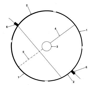
Fig. 1 shows top view and explains with the description of the embodiment how one skilled in the art could build their pioneering magnetic and/or electromagnetic motor.
Fig. 2 shows side view of commutator for tweaking invention depicted in Fig. 1 in order to use the collapsing magnetic field and current produced by the invention when the input voltage and current are broken during the cycle; and is explained with the description of the invention of Fig. 1.
Fig. 3 shows side view of adjustable firing of brushes leading to the motor of Fig. 1 that further tweaks the timing of the invention of Fig. 1 relative to its speed; and is explained with the description of the invention of Fig. 1.
DESCRIPTION OF THE EMBODIMENT
The drawing depicting the top view of Fig. 1 of the invention is easily understood by first look, not to follow inverse square direction of building electromagnetic devices. Because 20# rotary permanent magnet l is a noticeable distance of seven (7) inches from coil 5 of 70 lbs. of No. 5 gauge magnetic wire.
Nos. 6 and 7 or inner and outer housing of Fig. 1 encases coil 5 of Fig. 1. Magnet rotary 1 has three (3) inch diameter and is eight (8) inches long held by bearings and supports 3 and shaft 2 leads to power output at one end and stops with commutator 4 at opposite end of twenty -three (23) inches long, seventeen (17) inches wide and eleven (11) inches high coil 5 of inside measurements.
It is obvious this design is contrary to prior art teachings. And I now explain why it is phenomenally superior to the prior art. Fact: It is a known fact that the strongest magnetic field of a coil of magnetic wire is in its center. Note: Permanent magnet 20# magnetic rotary sits in the center of coil 5. Fact: Lenz's Law states as a moving magnet cuts wires at right angle or vice versa: "A current set up by an emf-induced due to the motion of a (closed- circuit) conductor will be in such a direction that its magnetic field will oppose the motion causing the emf." (1834)
Note: Magnet 20# rotary 1 is at noticeable distance from 70# coil 5; so, in accordance with the inverse square law, the magnetic field of rotary 1 is very weak at coil 5 itself. Therefore, Lenz's Law does not noticeably occur. And at the same time, the magnetic field of rotary 1 is extremely strong at the center of coil 5, exactly where the magnetic field strength of coil 5 is also strongest. Therefore, very strong torque is applied to magnet 20# rotary 1 of Fig. 1.
While at the same instant Lenz's Law by its strong rotation of 20# magnet is not enacted. Therefore, tremendously greater speeds and torque will result with tremendously greater efficient power output results than that of the prior art.
Any design of electromagnetic motor will benefit phenomenally by these pioneering teachings of this years-of-experience inventor.
The drawing of Fig. 2 is also of same experience and is also simple. Fig. 2 is standard double hub 3 for battery contacts with leads 4 and 5 leading to opposite firing segments of No. 1 with shortout segments 2 that are connected with dark solid line from segment 2 to other segment 2. That design results in a collapsing magnetic field of coil 5 of Fig. 1 producing current and magnetic field that maintains torque on rotating 20# magnet 1 of Fig. 1. Direction of input current is reversed, of course, at every 1/2 cycle.
Fig. 3 is of the same concern of improving performance by tuning the firing of Fig. 1 by adjusting brushes 6 by turning brush holder 7 mechanism that is a flat disk turnable by hand or by a mechanism for tuning firing with speed of Fig. 1 in rotation.
Of course, all of the problems I have discussed about the prior art and given solutions for, are even more accented if great number of turns of magnetic wire are used in the motor design.
The world will be dumbfounded by the results shown by the motors build by these teachings, but at the same time pleased with the phenomenal results and benefit to industry and to all humanity.
I accordingly depend on my claims for deserved patent protection for this pioneering patent application and patents issued by the grace of God. Amen.
WO2006093488
AN EFFICIENT WIND ACCELERATING AND WIND ENERGY PRODUCING DEVICE
AN EFFICIENT WIND ACCELERATING AND WIND ENERGY PRODUCING DEVICE
This device can come in various size, shapes and power and can vividly demonstrate the importance of certain scientific principles which have been left out or totally misunderstood by the prior art designs. This is why relevant prior art designs are very inefficient and their application results in much wasted wind energy (5). This innovation overcomes these errors of the prior art by in inacting known principles coupled with creativity and the knowledge of the solution to utilize the wind energy in a highly efficient means. An example of one application of the innovation (Fig.1) is detailed in the description of the embodiment. The wind energy producing device comprises one or more slide like incliner(s) (1) and one or more blunt-like member(s) (8) deflect and accelerate the wind (5) into the energy producing means of the device (2). The rotary energy producing means are aligned to the wind direction automatically by any conventional means.
The present invention relates generally to devices for releasing from the wind useable energy in an ever desiring efficient manner that is also practical to the user.
BACKGROUND OF THE INVENTION
There have been many devices since ancient time for releasing energy or work from the wind. However, they have been very restrictive in use and costly to install for the small amount of energy produced from the area taken up by the prior art.
Proof, look around the world today for the average home, farm, or industry using the prior art as an energy or work devices. They have ignored scientific principles and missused them in many cases to the detriment or inoperability of the claimed inventions.
Prior to this unique invention, the power of the wind inevidence across the world has only been vividly demonstrated by storms, tornados, hurricanes, etc. Not man's poorly designed wind devices deflectingwind away, energy away or works wind energy against itself and therein drastically reducing rotation of wind energy producing means.
This inventor has been observant of his environment since childhood and has been creative above others, even those skilled in the art. This pioner's invention is from that history of life. Looking earnestly and from his heart for the benefit of the poor people over the Earth, who needed a cheap and practical energy source to get a foot hold on life of quality. Wind which blows the trees, carries pollen, and cools the tired person is that answer.
It becomes obvious to the inventor; the present systems were very impractical for their needs. On studying why this was so, I observed that scientific facts were ignored. Convientional blades of the prior art are nothing more than the airplane wings and follow Bernoulli's effect across the top and bottom of the blades its entire length. Note: the wind hitting the blades on conventional windmills deflects the wind across and off the blades. At the same time, it is accelerating the wind energy and reducing the pressure over the blades and thereby causing the air being compressed on back side of blades in direction of rotation and therein causing breaking effect on blades because of reduced pressure on the front side of blades.
There is also a dead shot in the center of windmill which adds to this wasted wind energy. In fact, a quick demonstration of a child's hand-held device in front of a strong fan will clearly demonstrate the pushing power on the shaft supporting the wind device is a great or greater than the rotational power of the device itself.
Likewise patents already issued since 19th century to even now, trying to increase the velocity of wind into a rotating energy producing means. Such as US Patents: No. 264,164 (1882) granted to P.H. Jackson, No. 551,165 (1895) granted to J.F. Janssen, No. 648,442 (1900) granted to O.F. Scott, No. 757,800 (1904) granted to JJ. Williams, No. 1,345,022 (1920) granted to D.R. Oliver, No. 1,471,095 (1923) granted to D. Bonetto, No. 1,595,578 (1926) granted to L.G. Sovereign, No. 3,988,072 granted to D.L. Sellman, No. 4,019,828 (1977) granted to G.J. Bunzer, and No. 5,009,569 ((1991) granted to F. N. Hector Sr. All these patents have ignored Law of Gases.
They all describe means to have a large opening for the wind to come into and/or reduce the volume of said means down to smaller discharge of said wind into the rotating energy producing member hoping to utilize unrealistic wind velocity.
None of said patents address the truth of Science, and likewise none of said patents are operable as disclosed or claimed. Even worse, these patents obviously misled many potential inventors which worked against creativity and therein is the opposite of the purpose of providing foundation for creation of other patents worldwide.
This creative invention overcomes all of the above problems of conventional art and will definitely act as a stimulator of the creative mind individuals.
SUMMARY OF THE INVENTION
An object of the invention is to provide effective acceleration of the wind to maximize the wind energy transformed in the electric power by a generator.
This invention accomplishes the above objective by the device comprising one or more slide like incliner and one or more blunt-like member with slight incline attached to the perimeter of the mouth that deflect and accelerate the wind into the energy producing means of the device.
The wind energy producing device has the rotary energy producing means aligned to the wind direction automatically by any conventional means.
BRIEF DESCRIPTION OF THE DRAWINGS
Fig. 1 shows side view and explains with the description of the embodiment how one skilled in the art could build this revolutionary energy wind invention.
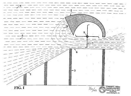
DESCRIPTION OF THE EMBODIMENT
The form or slide 1 can be made like a wide sliding board. Note: air pressure 4 Inertia 14.7 lbs per sq. inch at sea level. The air molecules 5 are moving left to right up and into opening 6 and rotable blade 7. Note by Brnoulli's Law: air 5 will accelerate going up slide 1. but at the same time, it is not being compressed hardly at all by height of slide 1.
Because the gas or air molecules 5 reach thousand of feet high, therein the Law of Gases is not being violated in this novel invention.
Housing has a blunt forward face at point 8. The air molecules collided against said blunt face 8 and are compressed stacking one another and they will collapse (similar to mud slide) against slight angel of blunt face at the accelerated rate into the mouth 6. Note again, air molecules 5 are free to move on the top or bottom of blunt face 8. The tests conducted by this inventor have proven that by tapering cone type devices of alone named patents cause air molecules 5 to move aside to the direction of the least resistance where after filling up the cone the majority of the wind goes around the cone. This is why said patents do not work as claimed. The blunt face 8 of this invention also sets molecules of air into the path of the list resistance, but only in this case, they go into the mouth of the wind producing mechanism rather than away from it. Therefore, what acts as a detriment to cone devises becomes advantageous when using blunt face(s) of this invention.
The design of blunt face of slight angle works to accelerate air molecules 5 into the mouth 6 of novel invention without violating Law of Gases, and rotate blades 7.
Example 8 feet high and 9 feet wide mouth 6 with 8 feet high and 9 feet wide blunt face 8 testing data by this inventor proved accelerating of air molecules 5 by a factor of three to one or three hundred percents, and that was without the slide 1 being used at all.
Accordingly, this novel invention can be used with only blunt face 8 or only slide 1. But the preferenced model uses both the slide 1 and blunt face 8 of this invention.
The slide 1 and rotary 7 and its housing are supported by supports 3. The slide 1 can be made with or without high side.
Remember, wind molecules 5 have pressure 4 at the sea level of 14.7 lbs/in<2> and therein inertia in direction of flow.
Also, the slide 1 can easily be made to face North, South, West and East with the housing 2 and rotary 7, and the shaft 9 fixed to rotate 360[deg.] with any conventional means to automatically align the mouth 6 to the wind 5 coming up active slide 1.
Also, the housing 2, blunt face 8, rotary blades 7, the shaft 9, and the mouth 6 can be made without slide 1 but also, automatically align the mouth 6 into the wind 5. Fanners can easily have dirt dug on their property, therein making a pond or lake for fishing and watering of plants with bulldozer build the slide 1 as described out of dirt and plant grass on it.
This novel invention explains and overcomes the prior art design of wind energy devices. And for the some reasons, this novel invention can produce noticably and practically wind velocities even in areas of normal low wind velocities.
WO8801245
ELECTROMAGNETIC DEVICE FOR MOVING AND/OR LIFTING ABOVE THE EARTH'S SURFACE AND EFFICIENT SPACE TRAVEL
ELECTROMAGNETIC DEVICE FOR MOVING AND/OR LIFTING ABOVE THE EARTH'S SURFACE AND EFFICIENT SPACE TRAVEL
A transporting, levitating device or space travel vehicle (32) which moves and/or lifts above the surface of the earth or other terrestrial body and performs effectively in space by means of generating an electromagnetic field which effectively interacts with the earth's, other planet's, satellite's, or the universe's electromagnetic field(s). The electromagnetic device functions as a result of a mathematical relationship of lines of force of the electromagnetic field of the vehicle effectively covering a large enough area, having for example a cross-sectional area across of fifty miles, of another supporting or influencing, surrounding, preexisting electromagnetic field, which may itself be weak in a small area, whereby the desired moving and/or lift capability is achieved for the electromagnetic device by interacting over said large area electromagnetically (magnetically).
BACKGROUND of INVENTION
1. Technical Field
The present invention relates generally to electromagnetic levitation devices for moving and/or lifting relative to its electromagnetic field interacting with the earth's or other terrestrial body's or the universe's electromagnetic field(s).
2. Background Art
There have been many claimed designs for achieving electromagnetic efficient and realistic travel in the air space surrounding a terrestrial body or space travel generally by the electromagnetic field generated by the device interacting with the earth's or other terrestrial body's or the universe's electromagnetic field(s). The National Aeronautical & Space Administration (NASA) of the U.S*, others, and even the fictional cartoon character "Dick Tract" have proposed such devices, but none were efficiently operable or practical.
These and other such devices of the prior art have not work efficiently or practically as a result of the prior lack of appreciation of the importance of producing a large electromagnetic field with a relatively small input power and the mechanics of the proper mathematical interactions of the device's emitted gyroscopic particles making up its electromagnetic field (magnetic) with those of the moving and/or lifting entity (planet-space-universe, etc.).
Additionally, the present invention utilizes in one exemplary embodiment the combination of a buoyant body or "air" ship and an electromagnetic field generator, which embodiment includes a synergistic inter-relationship and action between the produced magnetic field and the internally contained lifting gas (e.g. helium) , which inter-action enhances the lifting force or buoyancy of the lifting gas.
3. Objects of the Invention
Accordingly, it is a very basic object of the present invention to obviate the inefficient designs of the prior art by providing an electromagnetic device that will efficiently move and/or lift above the earth or other terrestrial body and/or efficiently travel in space regardless of the weakness or the strength or gauss of the supporting bodies' or space's electromagnetic (magnetic) field(s) by using a greatly increased area and strength of interaction between the respective electromagnetic fields over a relatively large area using for example a relatively low power electrical input.
A further object is to provide a levitation, space travel system in which there is included a buoyant "air" ship or lifting sub-system, in which system there is a lift enhancing interaction between the generated electromagnetic field of the device and the contained lifting fluid or gas, assisting in the inherent levitation capabilities of the system, particularly while traveling in the terrestrial body's atmosphere.
These and other objects of the present invention are provided, applying some of the teachings of U.S. patent application Serial No. 179,474 filed August 18, 1980, and its related U.S. & foreign ap-plications (note PCT International Publication No. WO 83/00963 dated March 17, 1983), and its related U.S. disclosure document, which teachings are included in the book entitled The Energv Machine of Joseph Newman (3rd ed.; Newman Publishing Co., Route 1, Box 2, Lucedale, MS 39452 USA; 1984-86), and combining them with the mechanics of generating a relatively large area electromagnetic field from a device that will functionally interact with relatively large areas of the electromagnetic (magnetic) field(s) of other bodies or space.The device preferably has sensing capabilities that automatically keep a check on the relative strength(s) of the electromagnetic field(s) of the bodies and/or space within the functional area of the device and, as a result thereof, also automatically adjust the generated electromagnetic field coming from the device for maintaining the proper, requisite electromagnetic interaction between generated field of the device and the supporting or influencing entities' electromagnetic (magnetic) field(s).
Another object of the invention is to properly mechanically interface the gyroscopic particles moving in the device's electromagnetic field with the gyroscopic particles moving in the supporting entities' electromagnetic field(s).
These and other advantages and objects of the invention will become more apparent from a review of the drawings and specification hereof.
BRIEF DESCRIPTION DESCRIPTION
The novel features of the invention are set out with particularity in the appended claims, but the invention will be understood more fully and clearly from the following detailed description of the preferred, exemplary embodiments of the invention as set forth in the accompanying drawings, in which:
Figure 1 is a side view of a first, exemplary embodiment of an electromagnetic (magnetic) levitating and/or motion device of the present invention for, for example, planetary and space travel.
Figure 2 is a top, plan view of an electromagnetic (magnetic) levitating and/or motion device for planetary and space travel.
Figure 3 is a top, plan view of another embodiment of an electromagnetic (magnetic) levitating and/or motion device for planetary and-space travel.
Figure 4 is a graph illustrating the coil power output line and the line ofXconstant ampere turns and total constant magnetic field strength in plotting the current in the coil or the watts required to sustain a magnetic field (vertical axis) against the number of turns in the coil (horizontal axis), which analysis is used in the consideration of the present invention.
Figure 5 is a perspective view of still another exemplary, embodiment of an electromagnetic (magnetic) levitating and/or motion device for, for example, planetary and space travel; while
Figure 6 is a top, plan view of the embodiment of Figure 5.
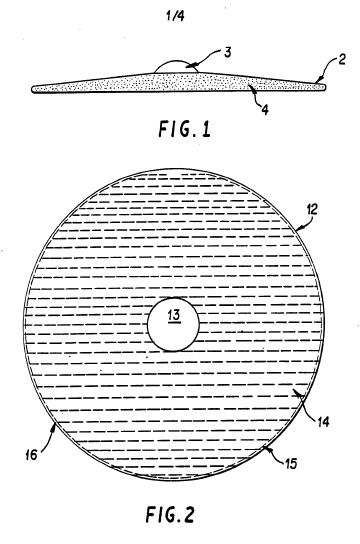
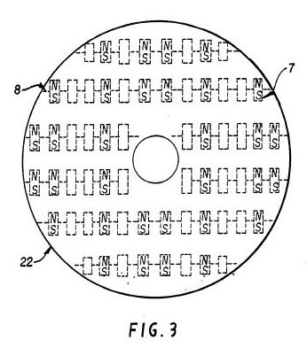
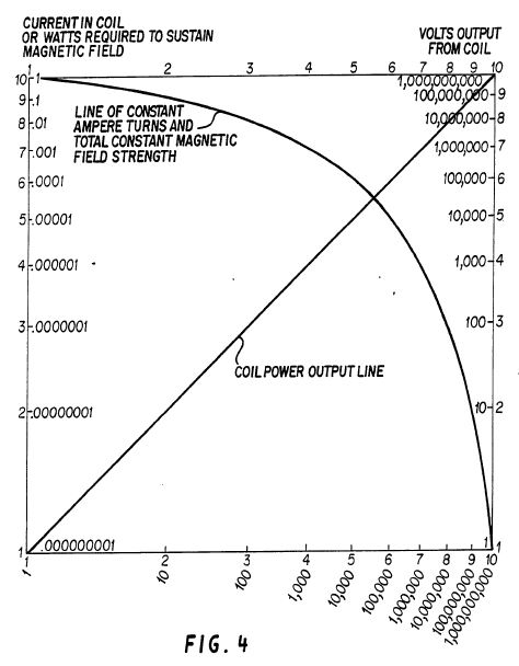
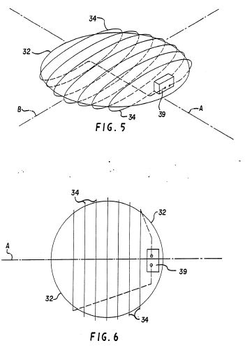
BEST MODES For Carrying Out The INVENTION
Referring first to Figure 1, a first exemplary embodiment of an electromagnetic (magnetic) levitating and/or motion device 2 for, for example, planetary and/or space travel, according to the present invention, is illustrated as viewed from the side. Although the device 2, is shown in the form of a dish or saucer, it could be made of numerous designs in other forms. An exemplary cargo or human area 3 is located for example in the center of the device 2.
Conducting medium or permanent magnets or super conducting electromagnetic field producing elements are schematically or generally illustrated as dots 4. The interior area of the dots 4 could also be filled with helium or some other light gas in place of, and lighter than, air and thereby have even more lifting capability in an atmospheric environment above a terrestrial body, as is more specifically discussed with respect to the embodiment of
Figures 5 & 6.
Referring now to Figure 2, a top view of a second exemplary embodiment 12, similar to the device 2 of Figure 1, is illustrated, with the electromagnetic field producing means 14 being of a conducting medium of numerous parallel means of relatively great length, resulting in covering or cutting across a significantly large area of the preexisting electromagnetic field of the supporting entity (planet, space, etc.). The parallel field generator means 14 has a relatively small input current and relatively high input voltage or uses super-conductive principles, running all in the same direction simultaneously through the parallel means 14.
One single conductor 15 on one end of the device 12 can be the initial input feed for all of the parallel conducting means 14 for the same polarity from an electrical energy source (not illustrated), for example a DC power source; with likewise one single conducting means 16 on the other end of the device 12 being the initial return route to the energy source. When the direction of the current, no matter how infinitesimally small, is reversed from the energy source by for example a commutator system, conductor means 15 then becomes the return path to the energy source, and conductor means 16 becomes the carrying or input path from the energy source, reversing the polarity of the electromagnetic field generated by the current flowing through the parallel elements 14.
For a full understanding and appreciation of this invention, one should master the teachings in PCT International Publication WO8300963 and its related disclosures and the book entitled The Energy Machine of Joseph Newman, all referred to above. Following those teachings and the disclosures hereof, one can build an electromagnetic device that will travel over land, air, water and/or space, by interacting with significantly large areas of the preexisting electromagnetic fields(s) of the earth, planets, or space, even though they be weak in considering only a small area, and as a result cause the device to levitate and/or move.
Preferably, but not absolutely essential in this design, relatively small diameter conducting wire of relatively great length and high voltage (hydraulic pressure) applied- or relatively small diameter super conducting material be used for the field generating elements 14 (4), whereby a strong electromagnetic field will result with relatively small current and wattage or power input. The purpose is to achieve the greatest area of electromagnetic field with the smallest weight factor that is practical.
For example, if the conducting parallel medium 14 was made of "40" gauge copper wire, each one would have a resistance of more than one hundred thousand (100,000) ohms for a saucer 12 with a slightly more than a twenty (20) mile diameter. For a slightly more than a one hundred (100) mile diameter, each parallel line 14 would have a resistance of five hundred thousand (500,000) ohms, allowing for only a small current flow even with high voltage.
These exemplary diameters at first may seem unwieldy large to the unthinking individual, but in space a diameter of one hundred (100) miles would be relatively less in proportion to the vastness of space, than a grain of salt is to the oceans of the world. As a result the living and/or cargo area 13 (3) could be of the largest area desirable; even including such large cross-sectional dimensions which would allow the building of a small, all sustaining, beautiful world with trees, animals, flowers, crops, streams, rivers, buildings, etc., with no pollution. Of course the diameter of the device 12 (2) would simply be increased according to the need.
At first one might think that such a massive device would use high current and power to create its needed large area electromagnetic field. In addition to the past teachings referred to above, the graph of Figure 4 is provided, utilizing the known scientific equation for the production of an electromagnetic field using a current flowing through a coil, which graph clearly proves that the power or current input can be infinitesimally small but yet produce a large, sustained electromagnetic field. Figure 4 shows the results of a coil, but the same effects apply if the coil was straightened out into the equivalent of the parallel lines 14 in Figure 2.
The fact that the invention will work is easily verified by the previous disclosures and by simply taking for example some t40 gauge magnetic copper wire and letting it hang between two supports about for example eight feet away, with an orientation so that the "40" gauge wire is at right angles to the earth's electromagnetic (magnetic) field and then putting about three hundred (300) volts to its ends (positive and negative). One will then observe that te magnetic n40n gauge wire will rise at an angle from the earth's surface when the current goes in one direction; and then will be attracted down at an angle to the earth's surface, when the current goes in the opposite direction. If momentary contact is made, only about one hundred (100) milliamps (M.A.) of current will flow, but the magnetic "40" gauge wire will rise or lower about a quarter of an inch.
For a given strength electromagnetic field, the lighter the conducting medium 14 (4) creating the electromagnetic (magnetic) field, the greater will be the ability of that conducting medium 14 (4) to lift and move itself and an additional load 13 (3), when interacting with the earth's or any other universal electromagnetic field.
The mechanical basis of the lift capability of the device 12 (2) is not unlike the history of the steel ship.
Conventional ship builders thought such was impossible, because everyone knew that a hunk of steel would sink and that a hunk of wood would float when placed in the medium of water. Of course, those negative, so called "experts" were proven wrong, because when the hunk of steel was made thin and spread out over a large area of the water's surface, not only would the steel be supported by the water, but it could also carry a massive cargo load.
The same type mechanical effect applies to the device 12 (2) relative to the earth's or other universal electromagnetic field. A tremendously strong, intense electromagnetic field restricted within 'a small area of the earth's magnetic field, for example a ten (10) foot diameter and only one foot thick device would not lift very much cargo 13 (3). However, if that same tremendously strong electromagnetic field was spread out over a very large area, thereby reducing its strength in a given small area of for example ten feet, the electromagnetic field interacting with a very large area within the earth's electromagnetic field would then lift an impressive cargo 13 (3) on the device 12 (2). This is because the earth's electromagnetic (magnetic) field is very weak in a small area but is tremendously strong over a very large area.
It is noted that the art did not have the ability by conventional means before the teachings referred to above to build a device to produce an electromagnetic field as large in area and strength as is the earth's. That has now changed.
The ability to utilize the teachings of the present invention most exactly will automatically relate into a mathematical formula, whereby to lift a given cargo load 13 (3) from earth would require a given strength and area electromagnetic field emitted from the device 12 (2) and properly mechanically interacting with a given area of the earth' s electromagnetic (magnetic) field. Because the strength of the earth's electromagnetic field varies over the earth's surface and at varying heights above the earth's surface, the derived mathematical equations will have to have appropriate safety margins; and even more so above the moon and some other planets.
The device 12 (2) for safety and practical reasons should have sensing capabilities that automatically keep a check on the strength of a body's or space's electromagnetic field within the functional area of device, and, as a result thereof, also automatically adjust the electromagnetic field coming from the conducting medium 14 (4) of the device 12 (2) for maintaining the proper electromagnetic interaction between the device and the supporting or influencing entities' electromagnetic (magnetic) field(s).
Based on tests and applicant's teachings, the device 12 (2) should lift off into space with less energy input at the earth's North and South electromagnetic poles, where a compass would point straight down toward the earth's center.
Example: prior teachings teach that, if current goes through a conductor in one direction and is attracted to a magnet, then, if the direction of the current is reversed, the conductor will be repelled from the magnet; or, if the current remains in the same direction through the conductor and it is attracted to a magnet and then the poles of the magnet are reversed, the conductor will be repelled from the magnet.
However, applicant's teachings of the mechanics of the gyroscopic particles in his prior work already stated and the facts of test prove that the above paragraph of conventional teachings is not true of all tests.
In fact, if a conductor of "40" gauge magnetic wire is placed to hang down just within the straighter lines of force emitted from the poles of a magnet, the conductor will be repelled no matter if the poles of the magnet are reversed or if the direction of the current in the conductor is reversed.
This test has been repeated numerous times over a hundred
(100) lb. permanent magnet one (1) foot long with a six (6) inch diameter. However, if the conductor is made longer to cover a wide distance extending out through the curved lines of force of the poles of the magnet, then the conductor will perform in accordance with conventional teachings.
Applicant's mechanical teachings of the gyroscopic particles making up all matter and electromagnetic fields predict the observed results of continuous repulsion of electromagnetic fields, if the different fields have their gyroscopic particles make up at right angles to the plane of their spins, thereby giving an opposite result to gravity's continuous attraction.
The device 12 of Figure 2 would therefore be able to take off easier at the magnetic poles of the earth, as those areas of where a compass points straight down cover a sizeable area.
The device 12 could be made to travel to any point on the earth, simply by changing the angles of interactions between the gyroscopic particles making up the electromagnetic field coming from the conducting medium 14 and the gyroscopic particles making up the electromagnetic (magnetic) field of the earth. The reversing and/or changing of the generated electromagnetic field coming from conducting medium 14 of the device 12 would cause the device to rise at an angle away from the earth or to lower at an opposite direction toward the earth.
The test of placing a magnet in a floating dish above a larger magnet will quickly demonstrate that the floating magnet can be made to go to the equator or the poles or towards or away from the larger magnet simply by changing the angle of the smaller magnet in the floating dish.
It is obvious from the known facts of science and space and the teachings of the invention that the embodiments of Figures 1 - 3 will work even better in outer space than when close to the earth's surface.
The device 12 (2) or some inner portion or outer portion thereof could be made to spin for stability and for achieving a force not unlike the feeling of gravity.
Figure 3 illustrates another, exemplary embodiment of the invention which has light-weight, permanent magnets or conducting or super conducting electromagnets 7 secured to a common means 8, which includes appropriate means to cause the electromagnets or permanent magnets 7 to all turn in unison, causing them to pivot to varying angles through an arc of three hundred and sixty (360) degrees relative to the electromagnetic (magnetic) field(s) of the supporting entity, namely those of the earth, space, etc., thereby giving exceedingly versatile motion to the device 32.
The conducting and/or super conducting electromagnets 7 should be of light weight and long turns of conducting medium, so as to use lower current or power to produce and maintain a large electromagnetic field covering a large area, as has already been taught.
It is noted that the conducting medium 4, .14 or 7 could be solid, liquid or gaseous in form.
A still further embodiment is illustrated in Figures 5 & 6, in which the device 32 includes a buoyant, "air" ship body of general saucer shape containing a lighter-than-air gas, for example helium, providing the device 32 with its own inherent lift when in an atmospheric environment.
A single, continuous coil of electrically conductive wire 34 is wrapped around the buoyant body with its two ends terminating at a power supply 39, which can for example be a DC source with a commutator sub-system to alternatively apply the flow of current through the coil 34 in alternating directions. As is well known, such current flow through the coil 34 produces an electromagnetic field having an axis A, which will flip back and forth in its polarity, in conjunction with the changing of the direction of the current flow from the electrical power source 39 through the coil 34.
As the coil 34 generates its electromagnetic field, the generated field interacts with the surrounding, preexisting magnetic field(s), causing the device 32 to rotate about an axis B, the particular direction of rotation and the particular alignment of which depends on the net axis or polarity of the surrounding, preexisting field(s).
Depending on the timing of the commutator sub-system in the power source 39, this will cause the device 32 to flip back-and-forth or, if the timing is right, to continuously rotate about the axis B, similar to a commutator of an electrical motor. Of course the commutator sub-system could be tied to the rotation of the device 32 to insure continuous rotation, if desired, similar in this respect to the action of a dynamotor. If such rotation is produced, it can be used to produce a simulation of gravity by the centripetal forces caused by the rotation. On the other hand, if so desired, the cargo and/or passenger area (comparable to area 3, 13) could be mounted on the body to allow it to remain relatively stationary with respect to the body, as the latter rotates.
Because the action of the electromagnetic field produced by the device 32 and its coil 34 is very similar to that described above, particularly with respect to* the device 12 and its parallel elements 14, further discussion on it is deemed unnecessary in the interest of brevity.
However, not only is there inherent, supplemental lift in the device 32 by the inclusion of a buoyant, lighter-than-air body, the lifting capabilities of the device produced by the buoyant body is enhanced by an interaction between the electromagnetic field produced by the coil 34 and the contained gas. This synergistic interaction further supplements the lifting capacity of the device 34, at least when in an atmospheric environment and perhaps even enhances the interaction between the generated electromagnetic field and the surrounding, preexisting magnetic field from the earth or other near terrestrial body or that of the universe generally.
In using the term "lighter-than-air't it should be understood that such is a relative term, depending upon the make up of the atmosphere of the terrestrial body in which the device is being used. Hence, the word "air" in this context should not necessarily be taken literally, but only in the sense that the contained gas should be less dense than that of the atmosphere in which it is being used.
Additionally, the contained gas is preferably one, for example a diamagnetic, which will inter-react synergistically with the generated electromagnetic field of the device.
It is noted in general that there are numerous other designs that can be built, such as for example using a circular, large conducting medium 4 (14/34) or made long like a cigar or any other shape, rather than that of the saucer or dish shapes shown. The devices 2, 12, 22 & 32 can be made very massive by being assembled in outer space. Also, rather than a single, contiguous buoyant body in the device 32, a series of spaced or juxtaposed, connected buoyant bodies or balloons could be used, with for example a coil of wire around each one or with one single coil about the whole assemblage.
Although the present invention has been illustrated in terms of four preferred, exemplary embodiments, it will be obvious to one of ordinary skill in the art that numerous modifications may be made without departing from the true spirit and scope of the invention, which is to be limited only by the appended claims.
This invention, as does the rest of applicant's work, opens tremendous new hope and dreams and excitement for the immediate future of the human race.
The present invention relates generally to devices or systems (including methods) for generating useable energy such as for example electrical energy from electromagnetic fields, electrical energy or electromagnetic fields from matter, and more particularly to devices or systems (including methods) for producing electrical current flow for use as electrical power, and magnetic fields of force which c.use motion (obvious work) or electrical current flow or for increasing electromagnetic potential energy available for use or mechanical energy available for use.
Claim 1. An electrical energy generation system for generating usable electrical energy, comprising: a source of at least one magnetic field: usable electrical energy output means associated with said magnetic field for making available for use the usable electrical energy generated in the system; and application means associated with said magnetic field for applying an adequate force at the proper angle to the gyroscopic type energy particles making up said magnetic field to cause said gyroscopic type energy particles to (11) AU-A-73601/87 -2follow a desired direction producing usable electrical energy at said output means, the amount of said usable electrical energy being greater than the amount of any external energy input to said source and said application means.
The method of generating usable energy, comprising the steps of: providing a magnetic device which has a material mass into which an electrical current is introduced, which results in causing pertinent atom alignment within said material mass, thereby releasing some of the electromagnetic energy making up the atoms of said material mass in the form of a magnetic field, causing the gyroscopic type energy particles of said magnetic field to then interact with the gyroscopic type energy particles making up a magnetic field coming from the atoms of a different material mass; and having the magnetic device then cause a release of usable energy through at least one power outlet and resulting in producing a greater energy output than external energy input into the device.
A device which increases the availability of usable electrical energy or usable motion, or both, from a given mass or masses by a device causing a controlled release of, or reaction to, the gyroscopic type energy particles making up or coming from the atoms of the mass or masses, which in turn, by any properly designed system, causes an energy output greater than the energy input.
Complete Specification
1. Field of the Invention
The present invention relates generally to devices or systems (including methods) for generating usable energy such as for example electrical energy from electromagnetic fields, electrical energy or electromagnetic fields from matter, and more particularly to devices or systems (including methods) for producing electrical current flow for use 10 as electrical power, and magnetic fields of force which cause motion (obvious work) or electrical current flow or *9 n for increasing electromagnetic potential energy available for use or mechanical energy available for use.
Prior Art:
There have been many devices proposed over the years C for producing electrical energy, with mechanical friction, thermoelectricity, photoelectricity, piezoelectricity, electrochemistry and electromagnetic induction being the 20 chief forms of primary energy capable of producing electricity. Of these, the only significant source of commercial electrical power has been the mechanical actions of electric generators, and for mobile electric power the chemical action of batteries has been important. Usable motion has resulted from the interactions between the input of electrical energy and the magnetic and/or electromagnetic fields of I -2force (electric motors) and heat or light as a result of input of electrical current through conventional mechanical systems, heaters, light bulbs, etc.
All of the prior art systems are designed accordingly to rigid mathematical laws taught both in physics and electrical engineering which coincide with the hypothesis rigidly accepted by the industrial and scientific communities concerning the Second Law of Thermodynamics (1850).
From the foregoing generally accepted hypothesis it has also been generally accepted and rigidly taught in physics and electrical engineering that the electric current flowing in a closed circuit from a battery, electric generator, etc. is used up in the mechanical device being operated by this 00* flow of electric current, and that all such electric current producing systems would only put out at most work equal to 0 the work initially put into the system, or in accordance e* 4 with generally accepted laws stating that a particular 20 electrical generating system was only capable of a given output of energy and no more.
These beliefs have till this date still remained rigid in both the industrial and scientific communities in spite 2 of proof of Einstein's equation cf E=MC^2 Nuclear reactors convert matter into usable electromagnetic energy in the form of heat, which converts water into steam to turn conventional turbines for production of electric current by conventional electrical generating means. This system is -3extremely inefficient using less than 1% of the energy of the atom and producing a deluge of contaminated materials which has caused a serious problem as to safe disposal.
Additionally, the basic electrical generators is use throughout the world today utilize the principle of causing relative movement between an electrical conductor (for example a rotor) and a magnetic field produced by a magnet or an electromagnet (for example a stator), all using the generally accepted hypothesis that the greater the relative speed or movement between the two are concerned and the more C* normal or perpendicular the relative movement of the conductive material to the lines of force of the electromagnetic field, the greater will be the efficiency of the prior art 15 electrical generator. Additionally, all of the prior art systems are based on the generally accepted hypothesis that the greater the electrical conductivity of the material being moved through the field, the more efficient will be the electrical generation.
From the foregoing generally accepted hypotheses, it also has been generally accepted that there should always be 9 movement between, for example, the rotor and stator elements, and that only generally accepted electrical conductors, that is materials with high electrical conductivity, will effectively serve in an electrical generation system.
However, in one of the systems (Figure 3) of the present invention, electrical generation can occur with relatively static elements and with materials that are not generally considered to be of high electrical conductivity, although, of course, the present invention likewise can utilize relatively moving elements as well as materials of generally accepted high electrical conductivity, if so desired, as occurs in the systems of the present invention illustrated in Figures 5 and 6.
The prior art has failed to understand certain physical aspects of matter and the makeup of electromagnetic fields, which failure is corrected by the present invention.
BRIEF DESCRIPTION OF DRAWINGS
For a further understanding of the nature and objects of the present invention, reference should be had to the detailed description, taken in conjunction with the accompanying drawings, in which like parts are given like reference numerals and wherein:
Figure 1 is a schematic, side view in generalized, representational form of a first embodiment of an electrical generator based on the principles and guidelines of the present invention.
Figure 2 is a close-up view in general form of an electrical charge pick-up element which can be used in the o OS generator illustrated in Figure 1.
Figure 3 is a schematic view in generalized, representational form of a second embodiment of an electrical generator .based on the principles and guidelines of the present invention.
Figure 4 is a schematic view in generalized, representational form of the negative and positive particles exhibiting gyroscopic actions which emanate from a magnet to form 0 an electromagnetic field.
Figures 5 and 6 are schematic views in generalized, representational form of third and fourth embodiments of a combined electrical generator and motor utilizing a static, relatively large coil energized by a relatively low current driving a rotatable magnet, wherein in the embodiment of Figure 5 the rotatable magnet is positioned along side of the coil and in the embodiment of Figure 6 the rotatable magnet is positioned within the open core of the coil 1
DETAILED DESCRIPTION OF PREFERRED EMBODIMENTS:
Basic Principles and Guidelines
In accordance with the principles of the present invention and as generally illustrated in Figure 4, an electromagnetic field 10 comprises f lows of or particles 20, 30 of electrical energy flowing from each of the poles 21, 31 of a magnet (or electromagnet) 40 to the other pole, following the "'lines; of force" 11 of the electromagnetic field. These particles 20, 30, believed to be traveling at the speed of light, are always coming out of one end 21, 31, respectively, of the magnet 40 and going into the other pole 31, 21, respectively, flowing from a relatively high energy source to a low energy source.
These particles 20, 30 are, it is believed, negative and positive charges and have a spin producing a gyroscopic 1, motion and follow the mechanical laws of gyroscopic action.
The mass of each of the particles 20, 30 equals the energy of the particle divided by the speed of light squared. The 00S peripheral speed of the gyroscopic spin of the particles is believed to be the speed of light.
For purposes of illustration only and as a matter of nomenclature, the positive charge particle 20 is going in one direction to with a clockwise spin, and the negative charge particle 30 is going in the opposite direction with a counter-clockwise spin. Off course, if a particle such as 20 or 30 is flipped around one-hundred-and-eighty degrees, it becomes the opposite charge or type of particle.
The electromagnetic field 10 is thus the orderly flow of the positive and negative charges 20, 30 moving at the speed of light from the north and south poles 21, 31, to the south and north poles 31, 21, respectively, and follow the paths of what is termed in the art as the "lines of force" 11 of the electromagnetic field As is known from the laws of gyroscopes, a gyroscopic particle or body moves at right angles to the direction of an applied force. Therefore, when a force is applied to the electrical energy particles 20, 30, they will move at right S angles to that force.
Sees It should also be noted from known gyroscopic laws that the electrical energy particles 20, 30, when they move with 15 their gyroscopic axis straight into an object, tend to knock that object straight, but, if that object hits the particles at an angle to the axis .other than at zero or one-hundred-and-eighty degrees, the particles are moved off at an angle from the straight.
Additionally, it is noted that a magnetic field caused by a current flowing through a wire comes from negative and S positive particles, such as 20, 30, with a net flow of such particles going in the same direction but with opposite spin.
In the system and method of the present invention, the foregoing principles serve as guidelines in the present invention.
Reference is further had to pages DD23 thru DD27 of the Disclosure Document and to page 8, line 26 through page 11, -8line 23 of the prior application Serial number 25,907 and its Figures 7 From the foregoing disclosures, many different devices, structures, and methods are possible to embody the principles and guidelines of the system of the present invention, which will in general utilize a material or substance or structure to place a force at the proper angle to the gyroscopic particles 20, 30 wherein the particles 20, follow a path or paths which do not cancel one another out, thereby producing electrical current at appropriate outputs for further use or for increasing available potential electrical energy for ultimate use.
First Embodiment (Figure 1)
One possible, exemplary embodiment using the principles of the system of the present invention is schematically shown in the generalized illustration of Figure 1.
As illustrated in Figure 1, there is provided an electrical current generator 100 comprising an outer keeper housing 115 and an inner, pressure containing, closed housing 116 supported therein by insulating supports 105. A vacuum exists in the area 106 between the two housings 115, 116, which vacuum is regulated and induced by means of the vacuum line 104 with its gauge 107 and its control valve 108. The outer housing 115 acts as a keeper for magnetic fields of force, and can be made for example of soft iron, while the vacuum in area 106 prevents the leakage or discharge of static electrical charges which might build up on the exterior of the inner housing 116.
A gas or gas-liquid mixture 117 which may also include solid particles such as for example lead or brass filings, is included within the inner housing 116 surrounding a series of aligned magnets 120 carried by insulating braces or supports 121 and producing a high, combined electromagnetic field. The magnets 120, which can for example be cryogenic magnets, have their "north" and "south" poles aligned (as illustrated by the "Ns" and so that their magnetic fields reinforce one another.
The level of the gas or gas-liquid mixture 117 in the housing 116 is regulated by means of the line 122 with its gauge 123 and control valve 124. Electric current output 0. wires 119 are provided and extend down to electrically connect with a wire pick-up system 118 (shown in close-up in 15 Figure which can be for example in the form of very small wires forming a closely spaced network or mesh or of a S porous conducting metal body or -sheet, located in and s g* extended throughout the fluid 117 in the housing 116.
It is noted that a thimbleful of gas contains a fantastically large number of extremely tiny bodies which 0 are in continuous, random motion moving at extremely high speeds. Hence, the fluid 117 continuously applies a force to the gyroscopic particles (analogous to particles 20, 30 of Figure 4) moving at the speed of light in the high electromagnetic field (produced by the magnets 120) as they continuously collide with each other, which results in the fluid 117 becoming electrically charged. The charged fluid 117 discharges its electrical charge to the pick-up wire network 118 positioned in the fluid, and the electric current so produced and generated is taken off for use via the electrical output wires 119.
As an alternative to having internally contained magnets 120, the electromagnetic field needed in the fluid 117 could be produced by a source located outside of the confines of the fluid 117 as long as a significant field was produced within the fluid 117.
Second Embodiment (Figure 3)
A further exemplary, generalized embodiment utilizing the principles of the system of the present invention is see*:<br/> shown in schematic form in Figure 3.
*The electrical current generator 200 of Figure 3 comprises an extended member 201 of a special material having its atoms especially aligned to produce electric current when positioned in an electromagnetic field but which does not on its own exhibit any substantial magnetic field outside of its boundary surfaces but substantially contains the field within itself. *This is in contrast to "magnetic" materials which likewise have atom alignment but which also exhibit or produce a substantial magnetic field in the area surrounding it.
The generator 200 further comprises for example two magnets 202, 203, with their north and south poles facing each other, with the member 201 positioned between them, and with the three elements 201-203 held static with respect to each other. Because of the special nature of the material of the member 201 and its special atom alignment, it will produce a direct current through output line 204 as a result of the gyroscopic actions of the particles of the electromagnetic field 205 produced by the facing magnets 202, 203, on the especially aligned atoms in member 201, which phenomenon occurs even when and even though the member 201 is completely static with respect to the magnets 212, 203.
However, it may be desirable in some applications to allow or produce some relative movement between the generator elements 201-203.
The output line 204 extends to an appropriate "load" 206 for using the electrical current generated by the generator 200. A return line 207 completes the circuit back to the member 201.
Based on experiments to date, it is believed that brass and lead are materials which can have their atoms especially aligned to interact with the gyroscopic particles (analogous to particles 20, 30) flowing between the magnets 202, 203 and will substantially contain within their surface boundaries the magnetic field produced by the aligned atoms or molecules.
With respect to producing the proper material with atom 20 alignment for the member 201, it is noted that most materials seem to align their atoms in random directions when formed by conventional methods of production. However, it can be observed that certain materials can be made magnetic by putting the material in an electromagnetic field while cooling from a temperature of around a thousand degrees Centigrade. The magnetism is the result of atom alignment of the material in a given direction (see pages DD19 thru DD21 of the Disclosure Document.) All materials are affected so as to align parallel or across lines of force when in a powerful electromagnetic field. Accordingly, if a material while being formed is cooled in an extremely powerful electromagnetic field, the atoms of the material will take a particular alignment. The atom alignment direction could be varied depending on whether the electromagnetic field was aligned with the material or at a ninety degree angle to the material. This would result in the atoms of a material having their particular electromagnetic spin direction primarily along the same axis.
However, merely having atom alignment is not sufficient. Additionally the material for the invention should o be such that it exhibits very little if any magnetic field in the area surrounding it. Thus it should be noted that the exterior electromagnetic field that occurs from the atom alignment of the conventional magnet is not duplicated in the material of the invention, because the electromagnetic energy resulting from atom alignment in the material of the invention will be primarily contained within the boundaries of the material. It is believed that lead, made superconductive by immersion in a bath of for example liquid helium, is such a special material could for example serve as the material for member 201, This then results in a material which would place a force at the proper angle on the gyroscopic type particles moving in the electromagnetic field so as to cause an EMF to be produced even when the material was sitting still. (See also first paragraph of page DD23 and paragraphs four, A through E, of page DD19 of the Disclosure Document.) It is believed that high, contained pressures, as well as other methods, can also probably produce atom alignment as the atoms of a conductor or any material will react to sufficient external force. (See first paragraph of page of the Disclosure Document.) This possibility is also indicated by the fact that hard knocks or impacts will demagnetize a magnet.
The proper procedure of material production in achieving atom alignment with internally contained fields of force will cause the controlled release of electrical energy in electromagnetic fields of force when the material of the invention is placed in the lines of force of the electromagnetic field.
Third and Fourth Embodiments (Figures 5 and 6)C A. Related Principles S1.
Numerous scientific tests and experiments made by the inventor indicate that the magnetic field resulting from an electrical current flowing through a conductor is the result of atom alignment within that conductor at an extremely fast speed with an ability to reverse atom alignment just as rapidly without the magnetic hysteresis associated with conventional materials considered "magnetic." Prior to this time it has been believed and taught by the scientific community that the magnetic field associated with an electric current carrying conductor was the result of the electric current itself and not of the conductor material, for example copper, which was considered to be "nonmagnetic.
Even the inventor was influenced and mislead by these teachings and attempted to mechanically explain and justify the prior teachings, as is seen on page DD-27 of the Disclosure Document which is an important part of this patent application.
However, as taught in the present invention, what mechanically happens is that the gyroscopic particles making up the electric current moving in a conductor interact with the electromagnetic makeup of the atoms of the conductor, causing them to align extremely rapidly, thereby then releasing some of their electromagnetic make-up in the form of a magnetic field exactly as explained in great detail for conventional magnetic materials in the Disclosure Document.
This is easily proven and understood by taking for 9 example a size "14" gauge conductor one foot long, winding it into a coil and connecting the coil to a meter and a 4 S* volt battery. The total current registered on the meter will be 1.5 volts and the strength of the magnetic field created from the short conductor will be extremely small. Next, the o• same type of test is run again but with the length of the conductor increased to for example two thousand feet, but still in a coil. The total current registered on the meter will now be considerably less, but the strength of the magnetic field given off from the conductor will now be extremely large! This shows that the magnetic field is not from the electric current flow, but is the result of the interactions of the gyroscopic particles which make up the electric current interacting with the atoms of the conductor! This causes the gyroscopic particles of the electric current not to be able to make the circuit back to the battery so quickly, and therefore the meter shows less current used.
The magnetic field is the result of the atom alignment of the conductor. The more atoms in a conductor (up to a the stronger the magnetic field produced from a given amount of electric current input. Again, this is proven by changing the diameter of the conducting wires, 00 and, with the lengths being the same, the strongest magnetic field will result from the conductor with the largest diameter. The reason for this is that there are more conducting atoms to interact with the gyroscopic particles of the electric current moving through the conductor, which results in a greater number of conducting atoms being aligned, thereby then releasing some of their electromagne2 0 tic make-up, exactly as has been explained in great detail in the Disclosure Document as being possible for all matter.
If the magnetic field produced was strictly based on the amount of current going through a conductor, as taught the prior art, then the strongest magnetic field would result when current went through a large diameter and short length conductor, because the current flow through the entire circuit is greatest at that time. However, experiments prove that the shorter a conductor is made, the greater the current flow through the entire circuit and the less strength of the magnetic field surrounding that conductor. The longer that same conductor is made (up to a point), the greater the magnetic field surrounding the total mass of the conductor and the less current that makes the complete circuit of the entire system. Reason: more atoms! 2. Numerous scientific tests and experiments made by the inventor also indicate that the magnetic field created when an electric current moves in a conductor does not use up measurable energy when performing obvious or unobvious work, force or power. This is true no matter how strong or how immense the power of the motor or electromagnets is.
Reason: the magnetic field coming from the conductor is the result of extremely quick atom alignment within that conductor. Therefore the energy in the magnetic field is the energy that makes up the atoms of the conductor! This energy OS is 2is literally Einstein's equation of E=MC and therefore the energy is believed to be moving at the speed of light.
This energy use cannot be measured by today's measuring instruments. This has been explained in great detail in the Disclosure Document and is believed to be true of all matter! 3. The same is true for the electric current that comes from a conventional battery. The electromagnetic energy coming from the battery is the energy that makes up the atoms of the material of the battery! Again this energy use is not measurable by today's measuring instruments. Electric -17meters of all types are simply mechanical devices which measure the amount of electric current that comes into that instrument. They do not measure the amount of mass that has been converted into electromagnetic energy.
Present teachings in science state that the electric energy flowing from a battery is used up in the device operated by that flow of electric current. This is not true at all! The electromagnetic energy released from the atom make-up of a battery has a relatively infinite capacity to do obvious work, a or power.
This is easily proven even with a small motor and a volt battery. With a battery connected to motor to operate 15 it and with a meter to take readings, the motor is then physically stopped from turning by physically holding or restraining the shaft. At that moment the motor is performing no obvious work, Agie or power, but the meter will register a greater flow of current. The magnets of the motor can be taken out and the reading will still be the same. If .i the electric current was being used to operate the motor, a the meter would register more current when the motor was running.
The electric current not only will operate the motor but, once it flows through the complete circuit back to the battery, it also does additional work based on Faraday's Laws of Electrolysis within the battery itself. What has happened is that the electromagnetic energy released from TI -18the atoms of the material of the battery once they have completed the circuit, then take a "short cut" and move large pieces of the mass of one material of the battery over to the other material of the battery. The inventor has stated and shown throughout the Disclosure Document that the effect of gravity was the unobvious effect of electromagnetic energy. Once the materials of the battery have combined, the extreme desire for the two materials to merge is physically reduced. These materials will attempt this merger anyway possible and, if. the electric current ini.tially released from a battery is not allowed by mechanical means to complete the circuit back within itself, the electromagnetic energy then in the mechanical means will perpetually (in a relative, theoretical sense) perform obvious work, or power. The reason: the force which initiated this flow of current (electromagnetic make-up of *0S. atoms of material) is constant, similar to hydraulic pressure, with the noticeable exception that it is moving it is see 0 believed at the speed of light and will interact with the electromagnetic make-up of the atoms of other materials, causing them to release some of their electromagnetic eS make-up in the form of a magnetic field. This then multiples the capacity for doing obvious or unobvious work, force or power, which can then react with another conducting coil or with the electromagnetic energy within the magnetic field of a conventional magnet and multiply this effect even further, and on and on and on for a relatively unlimited source of energy.
The same is true in not letting the current get back to \1 -19a conventional generator. If a mechanical means is set up so that the electric current is "trapped," without completing a circuit, the gyroscopic particles of the current have a capacity for continuous work without increasing the power input into the generator system. However, if the circuit is complete and the electric current moving in the system does absolutely no obvious work, power or force, the gyroscopic particles making up the current on getting back to the generator will then increase the need for more power input into the system. Reason: the opposing effect of magnetic fields as defined in Lentz's Law. This law is simply an observation of this effect, which before now has never been so fully understood.
Numerous scientific tests and experiments made by the inventor also indicate that there is a correlation between the electromagnetic spin orientation of the atoms of go nonconductors, semi-conductors, and conductors, and the 4 varying results achieved with an electric current in attempting to move through these materials, or when moving these materials through a magnetic field attempting to induce electric current.
The property of resistance to electric current movement is generally speaking the same type factor already explained above for electric current producing a magnetic field when moving in a conductor.
The gyroscopic particles in a moving electric current interact with the atoms of the material through which the current is moving. Each atom can efficiently only interact with an exact maximum amount of electric current, and, if exceeded, there is an interruption of orderly movement. Then the angle of release of the gyroscopic particles from the atoms are such that the electromagnetic release from those atoms are in the form of heat, exactly as explained in great detail in the Disclosure Document. This effect is easily observed by the fact that resistance decreases relative to an increase of the cross-section of the material. Reason: simply, more atoms within that given area, and, for a fixed input of electric current, there are more atoms to receive and interact efficiently with the gyroparticles making up the electric current.
Again the same is true for resistors designed for deliberately producing heat. Such resistors are not materials which are considered good conductors of electric current. It is stated and shown in great detail in the Disclosure Document that the electromagnetic spin orientation of the atoms of a nonconductor are different from that of conductor atoms, and therefore different results will occur from the same inputs of electromagnetic energy.
This is easily seen by the fact that, in a resistor, for a given amount of electric current input, the heat release increases as the diameter increases. What that means is that the property of resistance has decreased. On a conductor it is just the opposite. If the diameter is increased the resistance is decreased, but so is heat release. Again, this is an indication that the gyroparticles in the electric current movement interact with each atom of the material.
This same effect shows up again in conventional electrical induction from a conductor interacting with a magnetic field.
Experiments by the inventor have indicated that the property of conventional induction is the result of the same property of resistance.
If one increases the diameter of a conductor, lengths staying the same, one decreases the amount of electric current produced relative to the total number of atoms within the conductors under consideration. Or, if one takes Ges a given number of wires of the same diameter and length, and moves a magnet across them, the current produced will be 5 considerably less, than if one takes the same diameter wire, but only one wire, and increases its length considerably and then forms it into a coil forming the same number of wires on any one side and then moves the same magnet across only one side of that coil, the electric current generated will then be considerably greater. Reason: the property of resistance. This is the mechanical effect within the gyroscopic electromagnetic make-up and orientation of the atoms of all materials which have the mechanical ability to perform a given task efficiently up to a point concerning input of additional electromagnetic energy and then mechanically causes varying results once this threshold is exceeded.
This and all the other thoughts and innovations in this and the previous disclosures of the previous applications and the Disclosure Document previously put forth show that there are many different mechanical ways to release a relatively unlimited source of energy from electromagnetic energy which makes up all matter and which results from this invention.
Working Prototypes
Figures 5 and 6 illustrate rough, working prototypes of this aspect of the invention. These embodiments are only relatively inefficient prototypes built by hand for the purpose of demonstrating the invention. It should be be self-evident that the prototypes by various mechanical means and designs can easily be made extremely efficient, and the illustrated embodiments are being presented only for general, representational purposes.
As is illustrated in Figure 5, there is provided a combined electrical current generator and an electromagnetic motor comprising a rotatably mounted, permanent magnet 200, a battery 201, brushes and commutator 202, bearings 203 and power, mounting shaft 204, and a first, primary, magnetic producing coil 205 and a second, secondary electric producing coil 206. The two coils 205, 206 are juxtaposed together in parallel disposition with concurrent core center-lines, with the magnet 200 positioned alongside of coil 205 at or near its core center-line with the rotational axis of the shaft 204 positioned orthagonally to the center-line.
In the prototypes a very small battery 201, for example size of 1.5 volts is used.
When the circuit is completed, the battery 201 converts an immeasurable amount of its mass into electrical current (gyroscopic particles moving at the speed of light) which goes out through the communicator and brushes 202, and then enters magnetic producing conductor coil 205 made for example from insulated number "14" or "15" gauge copper wire, with the total weight of the coil 205 being for example seventy to ninety pounds. This causes the atoms of coil 205 to align extremely fast then releasing some of their electromagnetic make-up (gyroscopic particles) in the form of a magnetic field. This field then interacts with the gyroscopic particles making up the magnetic field coming from the atoms of the material of the permanent magnet 200.
This causes magnet 200 to attempt to align its magnetic field movement with the magnetic field movement coming from the atoms of coil 205, resulting in rotation of magnet 200 and the shaft 204 to which it is attached. This then changes the position of the commutator and brushes 202 relative to each other's initial positions, which then causes the electric current coming from battery 201 to be going in the opposite direction into coil 205, causing the atoms of coil 205 to extremely quickly reverse their alignment and the polarity of their magnetic field which they are emitting.
The reversed field then interacts again with the magnetic field of permanent magnet 200, causing it to further rotate.
This process is then continuously repeated producing continuous rotation of the shaft 204 which can be used as a source of motive power in many different ways. A power belt wheel 207 for example using a continuous belt is illustrated as a general representation of this motive power source for producing useful, obvious work. In a prototype test run with a small 1.5 volt, type battery, the shaft 204 and the magnet 200 rotated at a high speed for approximately twelve hours before running down. By improving the particular design features of the prototype and by using longer lasting batteries, the rotation time of the shaft 204 can be greatly increased to a theoretical point approaching "perpetual" for all practical purposes. At the same time the alternating magnetic field produced by the coil 205 induces into coil 206 electrical induction, which then causes coil 206 to produce an alternating current across its "load," which current can be made to exceed the conventional output o. of the battery 201. As needed the battery source 201 can be replaced.
It is very important to understand that, the longer the Of length of the conducting wire in coil 205, the stronger will be the magnetic field produced and the less electric current that will complete the circuit and get back into the battery and destroy the mechanical source of the electrical current.
This effect can be increased further by increasing the diameter of the conducting wire in coil 205 and then greatly increasing its length still further in the coil.
Reason: The gyroscopic particles making up the electric current interact with the atoms of coil 205. The more atoms in coil 205, relative to length, the longer it takes the gyroparticles of the electric current to influence them and get out the other end of the coil. It is then easily seen that, if the direction of the current into coil 205 is then reversed, this then further increases this lag time. Reason: The gyroscopic particles have inertia and are belie to be moving at the speed of light and are interacting with the gyroscopic particles making up the atoms of conducting coil 205. These atoms also have inertia and, when the direction of current is reversed into coil 205, the incoming current Sthen collides with the current already in coil 205 going in the opposite directions.
This causes a brief hesitation during the time the current already in the coil is being forced to reverse its direction, thereby then reversing the direction of the atoms within coil 205 which have already been influenced to become 20 aligned. This causes a constant force throughout the circuit, but does not allow very much current to get back into the battery 201 to destroy the mechanical means which initiated the release of electric current in the first place.
Therefore, it should be further understood that, the faster the current direction reverses into the coil 205, the more efficiently the matter of battery 201 is converted into pure electrical energy (E=MC2), without destruction of the mechanical situation that initiates the electrical current release.
It is also important to understand that, the stronger the magnetic field coming from the mass of magnet 200, the greater will be its rotational speed. Additionally, the greater the magnetic field coming from the mass of coil 205, the greater will be the rotational speed of magnet 200, and, up to a point, the greater the electric current input from battery 201, the greater the rotational speed of magnet 200.
Reason: the greater the electric current flow into coil 205, the greater will be the percentage of the atoms making up coil 205 that are aligned. This probably has the same relationship as does achieving atom alignment in conventional magnetic materials. Once complete atom alignment is reached in coil 205, no amount of current will cause those atoms to increase the strength of the magnetic field emitting from those atoms.
Therefore, it should be clear that, for a given input of electric current from battery 201, the most efficient design is one in which the most atoms of coil 205 are influenced to atom alignment by that given electric current, which means increasing the diameter and the length of the conducting wire of coil 205 to the point that the strength of the magnetic field produced is sufficient to cause rotation of the magnet 200 to a speed that allows none or at least very little of t..a electric current which initially comes from the battery 201 to complete the circuit and get -27back into battery 201 and destroy or reduce the mechanical effect which induced the conversion of the matter of battery 201 in electric current in the first place.
Again this desired effect can be increased by increasing the strength of the magnetic field given off by the atoms of the permanent magnet 200.
In the second prototype embodiment of Figure 6, the structure and operation of the .prototype is substantially identical to that of Figure 5 with the major exception being that the magnet 300/shaft 304 elements (and related sub-elements 302, 303 and 307) are positioned inside of and within the core of the primary coil 305, as compared to the >5 placement of the magnet 200/shaft 204 elements next to and along side of the coil 205 of Figure 5. Therefore, for brevity purposes, a detailed description of the elements of Figure 6 will not be repeated, but it is noted that the corresponding and analogous elements and sub-elements are similarly numbered in Figures 5 and 6.
It is also important to again stress the fact that the prototype designs shown are presented simply to prove the correctness of the invention, and it should be clear that the invention can be made extremely more efficient by utilizing all of the magnetic field produced by coil 205 and designing the magnet 200 of a shape and strength that efficiently interacts with the majority of the magnetic fields from coil 205. The illustrated prototypes is relatively highly inefficient in this regard, but even so the results of the invention itself greatly exceed the prior art as to use of electric current from whatever source and interaction with an electric motor or whatever work was conventionally performed.
The applicant feels it is very important to again stress, in building many varying designs of this invention, consideration must be given to the fact that the Energy in the field of force of any type magnet is the Energy that makes up the Atoms of the material from which it comes! This Energy is a real Entity with, it is believed, a gyroscopic action. It is literally Einstein's Equation of E=MC 2 And it is believed that this Energy moves at the speed of light and makes up all Matter. And that this Energy has a constant pressure effect back to the Atoms of the material from which it came, similar to hydraulic pressure.
This effect is additionally more fully understood by stating the following results obtaihed from experimentation by the applicant in the process of this invention.
When the system is initially attached to a 1.5 volt size Battery 201 or 301 and the magnet 200 or 300 and related rotation entities are placed close to or in the center of coil 205 or 305, the following results are observed: If the electric current produced in coil 206 (306) is then fed back into coil 205 (305) in accordance with proper polarity, the rotation speed of magnet 200 or 300 will then accelerate. If fed back into coil 205 (305) in wrong polarity, the rotation speed of magnet 200 (300) will slow -29down.
This proves that the total force from coil 205 (305) interacting with the magnet 200 (300) is greater when the electrical energy from coil 206 (306) is fed back into coil 205 (305), then when only the initial electric energy from battery 201 (301) is fed into coil 205 (305)! When two or three batteries are electrically connected together in series, so as to create for example three or four and one-half volts of electrical input, this effect is multiplied. Remember, up to a point, the greater the electrical input, the greater the percentage of atom alignment within coil 205 (305).
This further proves that the electric current produced in coil 206 (306) is a result of the gyroscopic particles of Energy released from the magnetic fields which came from the Electromagnetic make-up of the atoms of coil 205 (305), and 20 is not part of the initial Electrical Energy released from fee the atoms making up the materials of battery 201 (301)! The coil 206 (306) can be taken out of the system, or its electrical current fed away from the system, and the rotational speed of the magnet 200 (300) will not observably change. However, the rotational speed of magnet 200 (300) will noticeably change when the electric current from coil 206 (306) is fed back into coil 205 (305)! Now a different result: b) When the electric current from battery 201 (301) becomes weaker to the point that the magnetic field coming from coil 205 (305) has weakened and shrunk allowing the magnetic field of the rotating magnet 200 (300) to expand and then noticeably induce electric current into coil 206 (306) and into coil 205 (305). then reverse results are observed. When the magnetic field from the coil 205 (305) is large, then the magnetic field from magnet 200 (300) is retained! If coil 206 (306) is then short circuited, the rotation of magnet 200 (300) will noticeably slow down.
If electric current from coil 206 (306) is fed back into coil 205 (305) in wrong polarity, the rotation of the magnet 200 (300) will stop. If fed back into coil 205 (305) in correct polarity, the rotation of the magnet 200 (300) will slow down. At that point, rotation of the magnet 6 200 (300) will not accelerate, no matter how connected! .20 S These results show that, at this time, the magnetic field from magnet 200 (300) noticeably induces a current in coils 206 (306) and 205 (305) which opposes the rotation of the magnet 200 (300). This effect has already been mechanically explained, and it has been shown that Lenz' Law was simply an observation of that mechanical explanation.
These results further demonstrate that the expanding and collapsing magnetic fields from coil 205 (305) and 206 -31(306) do not noticeably effect each other detrimentally.
Because the resulting magnetic fields from all the coils are the results of fluctuating atom alignment within the coils! Remember, the gyroscopic energy particles making up the magnetic fields have a hydraulic pressure effect back to the atoms from which they came. Also remember that the atoms making up the material of the permanent magnet 200 (300) are stationary as to atom aligment direction! Therefore, the pressure effect resulting from an opposing field which the magnet 200 (300) induced, is immediate. However, the magnetic field emitted from the atoms of coil 205 (305) relative to induction into the atoms of coil 206 (306) are fluctuating and out of step, so to speak, and therefore, in harmony with each other. The pressure effect from the induction of coil 205 (305) into coil 206 (306) is an action and reaction effect which reinforces the flipping action of the atoms of coil 205 (305) and back into the atoms of coil 206 (306).
This action is again seen when the invention is hooked S into one-hundred-fifteen volt alternating current, and battery 201 (301) is not used.
The magnet 200 (300) will not rotate even though the magnetic field from coil 205 (305) is strong and is alternating. Reason, The fluctuating magnetic field is so fast, that the inertia mass of magnet 200 (300) can not get -32started in one direction before the magnetic field from coil 205 (306) has reversed, thereby, causing magnet 200 (300) to only microscopically vibrate at sixty cycles per second.
And, if a sixty watt bulb is connected into the system of coil 205 (306), it will only dimly light. And there is a lag time of two to three seconds before it lights even dimly.
If then coil 206 (306) is hooked to a meter, there is a reading of forty-nine volts, and if the meter is replaced by HIi another sixty watt bulb it will only extremely dimly light.
However, the sixty watt bulb hooked to coil 205 (305) will now noticeably become brighter! This again shows that the action and reaction results of the atoms of the coils are not noticeably detrimental to each other. Because of the lag time (out of step, so to speak), resulting in reinforcing the atom alignment of the coils.
From this further explanation of the invention it is seen that desirable results may be obtained by the following: 0.
For example, in Figure 6 the magnet 300 may be of a design and/or be located at a distance from the inside diameter of coil 305 and coil 306, whereby the majority of the magnetic field from the magnet 300 do not cut the conducting loops of coil 305 or 306. Yet the alternating magnetic field produced by coil 305 should efficiently have the majority of its gyroscopic particles interacting with the majority of the gyroscopic particles making up the magnetic field of the permanent magnet 300. But not directly reacting with the atoms making up coil 305, or magnet 300! When the magnetic lines of force of the magnet 200 (300) cross at right angles with the conducting wires of coil 205 (305), 206 (306), a braking action is incurred. It should be noted that, as the inner diameter of coil 205 ('305) increases, the percentage, of time of braking effect decreases.
Along this same line of instruction, the commutator O^ segments 202 (302) can be made of a large diameter and the area of brushes made small, whereby, when the brushes cross over the gaps in the commutator segments, there will be no short circuit at any time directly back to the battery 201 (301).
By combining the slip rings and brushes (the slip rings can be made of a small diameter) to the side or sides of the brushes and commutator segments 202 (302), then battery 201 (301) does not have to rotate with magnet 200 (300).
The No. "14" and No. "15" gauge copper insulated wire of seventy and ninety pounds (thirty one and one-half and forty and one-half kilograms) used for the motor coil 205 (305) and the generator coil 206 (306), respectively, in the first hand-made prototypes of the embodiments of Figure 34 and Figure 6, for demonstration purposes only, is standard wire obtained from wholesale outlets.
It was then wound in coils as shown, and, as taught, the more conducting wire used, the better the results. The magnets 200 and 300 were each initially about a two and one-half inch (six and one-quarter centimeters) cube and can be any size and strength desired.
In a further, rough, hand-built, demonstration, working prototype of the invention of the type illustrated in Figure 6, the primary or motor coil 305 was made of No. gauge copper wire in single, continuous wire form weighing approximately four thousand, one hundred pounds (one thousand, eight hundred and forty-five kilograms) with a coil loop diameter of four and one-half feet (one hundred and thirty-five centimeters), while the secondary or generator coil 306 was made of No. "24" gauge copper wire in single, continuous wire form weighing approximately three hundred pounds (one o hundred and thirty-five kilograms) with the same, approximate coil loop diameter of four and one-half feet (one hundred and thirty-five centimeters), with both coils 305, 306 coincidentally forming a cylinder of approximately thirty .inches (seventy-five centimeters) in length. The coils 305, 306 were built around a cylindrical, fiberglass core body of approximately two hundred pounds (ninety kilograms) having a vertical, longitudinal center-line axis.
The rotating magnet 300 was made up of six, separate, parallel cylindrical magnetic columns spaced and disposed about the periphery of a hollow cylindrical fiberglass surface of approximately twenty inch (fifty centimeter) in diameter. Each column was thirty inches (seventy-five cm.) long and was composed of a stack of seventy, individual ceramic ring magnets in disc form as made by Jobmaster Magnets of Randallstown, Maryland, 21133, U. S. A. Each disc had a thickness of seven-sixteenths of an inch (1.09375 centimeter), an inner diameter of one inch (2.5 cm.) and an outer diameter of four inches (ten The discs were stacked and secured together in four inch (ten cm.) diameter fiberglass tubes longitudinally mounted on the inner surface of the twenty inch (fifty cm.) diameter fiberglass cylinder.
The composite magnet 300 had a total weight of approximately four hundred pounds (one hundred and eighty kilograms) and a total length of thirty inches (seventy-five cm. and an approximate diameter of twenty inches (fifty cm.).
The magnet 300 was mounted for rotation on a horizontal shaft 304 extending across the hollow core of the coils 305, 306 crossing through the center point of the longitudinal center-line of the cylinder and orthogonally to the longitudinal center-line of the magnet 300 for rotation within the open center area of the cylindrically disposed coils 305, 306 with the longitudinal center-lines of the coils being vertically disposed.
With a D.C. battery source 301 of two twelve-volt (12 lantern batteries and seventeen six-volt 6 lantern batteries all in series (totaling one hundred and twenty-six volts), a measured voltage of one hundred and twenty-six volts and a measured current of ninety-nine milliamps in the primary coil 305 were noted. Concurrently a voltage reading of six hundred and forty volts and an amperage measurement in excess of twenty milliamps were noted in the secondary or generating coil 306, with the magnet 300 rotating at a speed of one hundred and twenty revolutions per minute (rpm). Thus the system was outputting and producing in the generating coil 306 usable electrical energy in excess of one hundred and two percent of that being inputted in the motor coil 3051 This excess useful electrical energy of course is in addition to the further useful mechanical energy available at the exemplary drive take-off 307 on the rotating shaft 304, on which the four hundred pound, thirty inch long magnet 300 was rotating at one hundred and twenty rpm! Thus the invention, by utilizing the energy of the gyroscopic particles in the magnetic field, produces a greater energy output than the energy input into the system, thus producing results beyond presently accepted scientific teachings of the world.
This prototype achieves exactly what has already been described in great detail in applicant's prior patent applications. There was simply used in this prototype a stronger magnet and a larger diameter conducting wire of great length, that has a considerably greater number of atoms aligned when current is put into the system, and used -37a greater number of atoms in the generator coil of fine diameter conducting wire.
While the results of the energy released from this particular prototype is highly impressive to others, applicant still has only scratched the surface of the energy that can be released using the principles of the present invention.
Again as has already been stressed the most efficient design, is one in which the least amount of input of current causes the greatest amount of atom alignment.
This data does not constitute any departure from applicant's previous work, but is only to further document that which has already been stressed in the prior patent applications.
Varying the D.C. voltage for 4 the battery source 301 shows that obvious efficiency will continue to rise s the voltage input goes up! Also the leverage factor advantage of the invention, combined with the inertia of the four hundred pound magnet 300 rotating at one hundred and twenty rpm (even while causing the electrical generator to put out over 100% of energy input) proves the invention to be greatly over 100% efficient even at this slow rpm.
It is contemplated that the next prototype will use super-conducting type material for the coil 305 with a magnet 300 having a magnetic field strength comparable to that of cryogenic-type magnet relative to percentage of atom alignment or size.
This will result in the size of the generation system being much smaller and yet with the available work output being much greater than the prototype just described.
Reason: The most efficient type design is one whereby the 10 least amount of current input into the motor coil produces the greatest atom alignment of said motor coil and having rotatable magnet also comparable in strength, relative to size.
The invention can be made without using the coil 15 206 (306) and producing just useful mechanical energy.
Coil 206 (306) can be merged or wound with coil 205 (305).
The magnet 200 (300 may be of any type including an 0 S" 20 electromagnet, permanent magnet, or a cryogenic magnet.
The design of magnet 200 (300) can create a strong but retained magnetic field.
The design of coil 205 (305) can be used to further retain the magnetic field of magnet 200 (300).
Alternating current can be used in place of the direct current batter 201 (301), if the magnet 200 (300) is designed accordingly.
The coils 205 (305) and 206 (306) may be made up of several coils rather than a single coil.
The magnet 200 (300) may be made up of several individual magnets rather than from just a single magnet.
From the foregoing it should be understood that, unlike the teachings of the prior art, the following is desired in the design of the coil 205/305 under the principles of the present invention: a) current initially flowing into and through the coil C should be small compared to the energy output of the system; b) a relatively large diameter wire or its equivalent is used for the coil; c) a relatively large number of coil loops or coils is used; d) a relative long, continuous length of coil wire or its equivalent is used; and e) the greatest magnetism for a given mass of the magnet 200/300 is desired but may be designed so that the magnetic lines of force will not cut the coils at a right angle.
The present invention applies to any mechanical device which is operated by electrical energy. In accordance with the principles of the present invention, the mechanical device should be designed wherein the electric current as much as is feasible cannot get back to its source, but the circuit is completed whereby the "pressure fnrze" is constant throughout the system.
What has been invented, built and disclosed is an invention of immense importance to the well-being of the entire world. There will be many devices built from what has been shown and taught. It should now be known that all .natter is made up of electromagnetic energy and that there are many mechanical ways to release this energy, as has been stated throughout the five prior, related patent applications hereof and the Disclosure Document. All of these future developments will be as- a result of the present 10 invention which releases energy above and beyond conventional energy release mechanisms, prior to this invention.
Some of the basic approaches of the invention are outlined below: 1. Any device which utilizes a means by which the electric current (electromagnetic energy) is retained within a member or members outside, of the source of said original electric current and then, as a result thereof, is capable of producing a continuous electromagnetic motion or current if so desired beyond present scientific teachings.
Any device which releases the electromagnetic energy make up of matter to such an impressive degree as does this invention that it defies several of the present accepted laws of physics and electrical engineering as of this time.
3. That the energy release is noticeably higher and in -41some cases more controllable than the conventional means of energy release of this time.
WO2008069799
BOAT PROPULSION DEVICE
BOAT PROPULSION DEVICE
This boat propulsion device can come in various sizes, shapes and power and can vividly demonstrate the importance of certain scientific principles which have been left out or totally misunderstood by the prior art designs. The boat propulsion device comprises thrust and force member systems of a boat or ship performing way above the accepted horrible inefficient 3% or so boat and ship thrust and force devices used before this pioneering invention, by being phenomenally more efficient thrust and force member through being moved through the water in a mostly straight line a proper distance creating greater and greater thrust and force with speed, but avoids cavitation or detrimental voids momentarily created when water is firmly pushed in any direction and thereby easily being onto and/or more than a 1000% more efficient than prior art devices.
FIELD OF THE INVENTION
The present invention relates to devices for producing propulsion to boats or ships moving in or on medium water that is novel and pioneering in its efficient result that is strikingly contrary to the extremely inefficient prior art.
BACKGROUND OF THE INVENTION
Means for propelling boats go back to ancient times and have been diverse in design. From poles, oars, sails and propellers, etc.
In recent times they have followed status quo accepted methods that facilitate the use of devices other than man for power. Especially the propeller coined by so-called experts "the power of the screw" which proves they were not thinking. Because the ability of a screw to apply force or pressure is dependant upon density or hardness of the medium, the screw is penetrating.
Example: Turn a screw into a Jello(R) medium and you get no real pressure or force likewise in water to some extent. Art of pumps show propellers cannot produce high pressure or P.S.I, and are not considered positive displacement pumps.
Accordingly, now surprisingly, the prior art devices are notoriously inefficient getting a mere two or three miles to the gallon, or less, of combustible fuels used and/or being about 3% efficient of its power source.
SUMMARY OF THE INVENTION
It becomes obvious to the inventor from over 45 years of study, research, deep thinking and experimentation, that there is a way that rises above the inefficient limitations of prior art. By taking in the mathematical relationship of the medium of water so as to function in a very efficient manner to propel boats or ships, density and gravity considered, results in remarkable results.
An object of the invention is to provide an effective boat propulsion means thus resulting in phenomenally faster speeds and efficiencies relative to the horsepower of power sources used today. This goal is achieved by a novel and pioneering design in that the boat propulsion device takes into consideration that the velocity of water to fill a cavity in water is dependant upon gravity, wherein the means of the invention does not violate that fact - nor produce cavitation and the result gives a positive force of propulsion by considering the density of water and the effect of gravity upon water simultaneously that can result in exacting and predictable forces and propulsion of a given boat at a high efficiencies and speeds and control far above an inefficient prior art achieving only a mere 3% or so of the horsepower source.
The propulsion boat members of the invention are pulled in a straight line (not an arc) a proper and practical distance before coming out of the water and traveling back to the opposite end, then emerging again into the water repeating said motion of propulsion means that keep proper distance between the members wherein they do not hit cavities of system in the water that were temporarily caused by the member in front of one another. The width and depth and speed are relative to force or thrust needed for a given boat or ship. On a ship there may be a number of members or systems even offset and so pulled a goodly distance. The members could be offset of any system and designed to collapse when not in propulsion position and therein be completely underwater and still function efficiently and practically. They can be designed to function on both sides of the ship with a system - wherein control and very quick and sharp turns can be accomplished.
No rudder would be needed. Reverse and stoppage can be very quick. There can be numerous systems for greater thrust and force and speed and distance between members. In short, a boat propulsion means that can now cause a boat or ship to function as easily and efficiently, or even more so, as a land vehicle. Even a submarine can use this principle to perform with more agility.
BRIEF DESCRIPTION OF DRAWINGS
Figure 1 shows the top view and shows embodiments applied to a boat and with the description explains how and why one skilled in art would and could build this extremely efficient pioneering invention for boats and ships of any type. Figure 2 shows the side view of the embodiment and with the description explains easily how one skilled in the art could apply its phenomenal results to any boat or ship of any type.
DESCRIPTION OF THE EMBODIMENT
The drawing depicting the top view of Figure 1 of the invention is easily understood by first look and description now given: 1 are chain sprockets and 2 are thrust and force members that through Chain 3 connection to Motors 4 propel the boat forward or backward or sharp 90[deg.] turns or 360[deg.] complete turn around and stay in the same area.
Thrust members 2 apply a greater and greater force or thrust with speed of straight direction and avoidance of any cavity caused by another thrust member 2.
Fort turning, one slows down one Motor 4 of one side of boat while other motor 4 runs at faster speed. Backing up simply run motors 4 in reverse direction or have transmission between Motor 4 and attachment to shaft of sprockets 1 of system. The drawing depicting the side view of Figure 2 is easily understood by one skilled in the art, but what has not been understood by those skilled in the art is why thrust members 2 would give result phenomenally superior to propellers now used universally on earth.
The reason is understood if one pulls the ancient paddle in the water and then looks down at the momentary cavity created behind direction of paddle. A propeller is like several paddle blades at an angel and connected to a rotatable shaft. Therein the propeller creates the same similar problem and they use the word "cavitation."
The pioneering invention here of thrust members 2 and Figure 1 and Figure 2 purposely avoid those critical problems of propulsion. In fact, tests clearly prove thrust and force are shockingly demonstrated on propulsion of a boat so design as disclosed way beyond the dismal effectiveness of propellers, etc. of prior accepted art.
The world will be dumbfounded by the results shown in the application by thrust members 2 of this system pioneering invention to boats and ships of the world but at the same time pleased and joyful with the phenomenal results and benefit to industry and humanity. I accordingly depend on my claims for deserved patent protection for this pioneering patent application and patents issued by the grace of God, Amen.