Peter
PLICHTA
Silane Fuel
http://webmoneymerlin.com/top-secret-new-free-energy-source-discovered-in-switzerland-governments-big-corporate-investors-trying-to-keep-it-secret/
Top
Secret New Free Energy Source Discovered In Switzerland –
Governments & Big Corporate Investors Trying To Keep
It Secret
by Lie
Sniffer
Transforming
Sand Into Fuel - Silicon Oil As A Vitality Bearer
http://blog.hasslberger.com/2010/03/turning_sand_into_fuel_silicon.html
Turning
Sand into fuel - Silicon oil as an energy carrier
by
Sepp Hasslberger
Dr Peter Plichta studied chemistry, physics and nuclear
chemistry in Cologne, Germany. He obtained his doctorate in
chemistry in 1970, and in the years following he did much
research, on the subject of silanes. Similar to hydrocarbons,
silanes are hydrosilicons, molecules that incorporate atoms of
both silicon and hydrogen.
Plichta also studied law, and in the 1980s he studied and
researched logics, numbers theory and mathematics. As a
result, he published several books outlining a new theory on
prime numbers in German. In this article however, I will only
discuss his proposal to use silanes as a highly energetic
fuel.
Silicon is more abundant than carbon. It oxidizes or combines
with oxygen into silicon dioxide, which forms crystals present
in rocks like quartz, basalt and granite. Silicon dioxide is
especially prevalent in sand which fills deserts and sea
shores. We process silicon dioxide into glass and purify the
silicon for use in electronics. Both of those processes
require much external energy input.
Before the 1970s, silanes were considered unsuitable for use
as fuels, because they instantaneously self-combust at room
temperature. Not satisfied to leave it at that however,
Plichta went to work and succeeded in producing longer-chained
silanes that appeared as clear, oily liquids and were stable
at room temperature. He argues that these higher (long-chain)
silanes could be used as an abundant fuel as an alternative to
both hydrocarbons and pure hydrogen.
Unlike hydrocarbons, silanes use both the nitrogen and the
oxygen in air for combustion. While the hydrogen component of
silanes reacts with oxygen, the silicon oxidizes in a highly
energetic reaction with nitrogen. So the burning of silanes
produces much higher temperatures and frees more energy than
the burning of hydrocarbon fuels. The silane reaction leaves
no toxic residues.
Much of the information in this article comes from a recent
description of Plichta's discoveries and his proposed silane
fuel cycle written by Norbert Knobloch and published in the
German magazine Raum & Zeit.
Peter Plichta's book "Benzin aus Sand" (Gasoline from Sand),
first published in 2001, advocates a change in energy strategy
away from burning hydrocarbons to using the energy potential
of silanes or, as I would term them, hydrosilicates....
The book, so far only in German, is available from Amazon:
http://www.amazon.de/s/ref=nb_ss_b?__mk_de_DE=%C5M%C5Z%D5%D1&url=search-alias%3Dstripbooks&field-keywords=Peter+Plichta&x=0&y=0
Nitrogen
oxidizes silicon
Silicon is the most abundant element in the earth's crust.
Combined with hydrogen, silicon forms what in chemistry are
known as "silanes". Given sufficient heat, silanes react with
the nitrogen in the air. This is a new discovery. Nitrogen was
thought to be inert, as far as combustion is concerned. So we
obviously must re-think the possibilities of combustion.
Silicon makes up 25% of the earth's crust, while nitrogen
makes up 80% of air. A process that uses silicon/nitrogen
combustion in addition to the known carbon/oxygen cycle,
presages some mind boggling new possibilities.
While carbon is also a relatively abundant element, its
prevalence is way lower than that of silicon. The relation is
about a hundred to one. In addition, most of the available
carbon is bound up in carbonaceous minerals such as marble and
other carbon-based rocks and some of it is in the atmosphere
as carbon dioxide. Those forms are not available for use in
the combustion cycle. Only one in about a hundred thousand
carbon molecules is bound to hydrogen, making it available for
the purpose of combustion. So while carbon has served us well
for the first century and a half of industrialization, it is a
rather limited fuel.
Using
100% of air for combustion
Plichta's idea was to exchange chains of carbon atoms in
hydrocarbons for chains of silicon in hydrosilicons or
silanes. The long chained "higher silanes" are those with five
or more silicon atoms in each molecule. They are of oily
consistency and they give off their energy in a very fast,
highly energetic combustion.
While hydrocarbon-based gasoline only uses oxygen, which makes
up 20% of air, for their combustion, the hydrosilicon-based
silanes also use nitrogen, which makes up the other 80% of
air, when they burn. Silanes with chains of seven or more
atoms of silicon per molecule are stable and can be pumped and
stored very much like gasoline and other carbon-based liquid
fuels.
The efficiency of combustion depends on the amount of heat
that is created. Expanding gases drive pistons or turbines.
When hydrocarbons are burned with air as the oxidant,
efficiency of combustion is limited by the fact that the 20%
of air that partakes in the combustion also has to heat up the
nitrogen gas, which isn't participating but has to be expanded
as well. When burning silanes, practically all of the air
participates directly in the combustion cycle, making for a
much more efficient expansion of all the gases involved.
Burning
silanes
The combustion process of hydrosilicons is fundamentally
different from the exclusively oxygen based combustion we know
from burning hydrocarbons. In a sufficiently hot reaction
chamber, silanes separate into atoms of hydrogen and silicon,
which immediately mix with the oxygen and nitrogen of the air.
The hydrogen from the silanes and the air's oxygen now burn
completely leaving only water vapor, bringing the temperature
of the gases close to 2000 degrees C.
Since there is no more oxygen, no silicon oxide can be formed
in the following phase. What happens instead is an extremely
energetic reaction of the 80% nitrogen in the air with the
silicon atoms present, that forms a fine powder called silicon
nitride (Si3N4).
For those more technically inclined, taking the example of
hexasilane (Si6H14), here is what the reaction would look
like:
2 Si6H14 + 7 O2 + 8 N2 -> 4 Si3N4 + 14 H2O
After this first reaction, a great deal of unreacted nitrogen
is still in the combustion gases, which would now react in a
stochiometric combustion as follows:
4 1/2 Si6H14 + 18 N2 -> 9 Si3N4 + 63 H
Overall, on the input side of the equation we would have:
6 1/2 Si6 H14 + 7 O2 + 26 N2
and on the output side, we get:
14 H2O + 13 Si3N4 + 63 H
The silicon nitride we find in the "exhaust" is the only known
noble gas that exists in solid form, an original discovery by
Peter Plichta. That white powdery stuff is a rather valuable
raw material for ceramics.
Wikipedia says that silicon nitride powder will form "... a
hard ceramic having high strength over a broad temperature
range, moderate thermal conductivity, low coefficient of
thermal expansion, moderately high elastic modulus, and
unusually high fracture toughness for a ceramic. This
combination of properties leads to excellent thermal shock
resistance, ability to withstand high structural loads to high
temperature, and superior wear resistance. Silicon nitride is
mostly used in high-endurance and high-temperature
applications, such as gas turbines, car engine parts, bearings
and metal working and cutting tools. Silicon nitride bearings
are used in the main engines of the NASA's Space shuttles."
Rocket
fuel for space propulsion
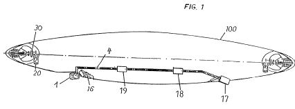
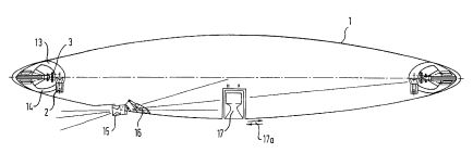
One of the first uses Peter Plichta envisioned for these
long-chain hydrosilicons he discovered was to be a fuel for
rockets. Space travel today is hindered by the immense weight
of fuel a rocket has to carry to lift itself plus the fuel,
plus its payload, into space. With a more efficient combustion
process, and an oxidant that could be "scooped up" in the
atmosphere, a disk-shaped craft could be propelled to great
speed and altitude, before having to fall back on a rather
small amount of oxidant that may be carried as liquefied air
or liquid nitrogen.
I found a discussion of this on the net, here, which I
reproduce below in shortened and slightly edited form:
http://discaircraft.greyfalcon.us/Richard%20Miethe.htm
"Dr Plichta can use his concepts of cyclic mathematics to
effect a revolution in space travel. He has already received
several patents for the construction of a disc-shaped reusable
spacecraft which will be fueled by the diesel oils of silicon.
The special feature of these carbon analog substances is that
they do not only burn with oxygen, but also with nitrogen.
Such a spacecraft can use the atmosphere for buoyance. Its
engines can inhale air and thus do without the standard
oxidant reservoir.
"In 1970 Peter Plichta disproved the textbook theory that the
higher silanes are unstable. One of his achievements was to
create a mixture of silanes with the chain lengths 5 to 10
(Si5H12 to Si10H22). He also managed to separate the oil into
the individual silanes by of means gas chromatic analysis.
This showed the surprising result that silanes with a chain
length of over 7 silicon atoms will no longer ignite
spontaneously and can thus be used for commercial purposes.
"Multi-stage rockets function from the mathematical point of
view according to principles of rocket ascent. At the first
stage of the launch they have to lift their whole weight with
the power of fuel combustion. Because they quickly lose weight
as they use up fuel, they then accelerate although the power
of thrust remains the same. The discarded stages are burned in
the atmosphere, which can only be described as a ridiculous
waste of money. The Space Shuttle was intended to make space
travel less costly; but actually the opposite has happened.
Just as the invention of the wheel made all human transport
easier, a circular spacecraft will some day soon replace the
linear design of current multi-stage rockets. We are all
familiar with the elegance with which a disc or a Frisbee is
borne by the air through which it flies.
"Peter Plichta got the idea of constructing a disc in which
jet-turbines attached to shafts would drive two ring-shaped
blade rings rotating in opposite directions. This will cause
the disc to be suspended by the air just like a helicopter.
The craft can then be driven sideways by means of a drop-down
rocket engine. When a speed of over 200 km/h has been reached,
the turbines for the blade rings will be switched off and
covered to enhance the aerodynamic features of the shape. The
craft will now be borne by the up-draught of the air, just
like an aircraft is. This will also mean that the critical
power required for rocket ascent will not be necessary. When
the spacecraft accelerates into orbit, the N2/O2 mixture of
the air will first be fed in through a drop-down air intake,
as long as the craft is still at a low altitude of 30 km (1
per cent air pressure). The air will be conducted to the
rocket motor and the craft will thus accelerate to a speed of
5000-8000 km/h. This is where a standard rocket jettisons its
first stage, because by then about 75% of the fuel has already
been used up.
"The disc on the other hand will continue to accelerate to
20,000 km/h and will thus reach an altitude of about 50 km (1
per thousand of air pressure). The speed will increase as the
air pressure drops, so that the process can be continued until
an altitude of about 80 kilometers and 25,000 km/h can be
maintained. In order to reach the required speed of 30,000
km/h and an altitude of around 300 km, only a relatively small
quantity of oxidation agent will be needed at the end.
"In the hot combustion chamber silanes decompose spontaneously
into hydrogen and silicon radicals. The hydrogen is burned by
the oxygen in the air and water formed. Because molecular
nitrogen is very tightly bonded, it must be preheated and
subjected to catalytic dissociation. The extremely hot silicon
radicals will provide additional support for this process,
which will in turn lead to silicon nitride being formed. In
order to burn superfluous nitrogen, Mg, Al or Si powder can be
added to the silane oil.
"When the spacecraft returns from space the ceramic-protected
underside of the disc will brake its speed to approximately
500 km/h. Then the covering will open again, making the blade
rings autorotate. The jet turbines will then be started for
the actual landing operation..."
In 2006, Plichta developed a new low-cost procedure for the
production of highly purified silicon. This makes it possibile
to hypothesize a more widespread use of silanes. If widely and
cheaply available one day, the new fuel could be used in
turbines and modified internal combustion engines, in addition
to space rocket use.
Large-scale
production of silanes
In order to use long-chain silanes as a fuel, the possibility
of large scale production of those silicon oils will have to
be experimentally confirmed. According to Plichta, this
process would also involve production of pure silicon for use
in photovoltaic or other industrial applications. High grade
energy is needed to transform silicon oxide into pure silicon,
to be hydrated producing the silanes.
One possible way to go about this is to use photovoltaic
electricity to disassociate hydrogen and oxygen from water.
Those gases could then be used to process sand into pure
silicon and to obtain silanes.
Another procedure, widely used today, is to purify silicon
dioxide using heat from coal, but Plichta has now developed a
new process that would use tar, pitch and bitumen as well as
aluminium silicate to produce pure silicon and silanes at a
very low cost. The highly exothermic process produces large
amounts of hydrogen and it involves super heated hydrogen
fluoride. Monosilanes, a by-product of this new process, could
be reacted with carbon dioxide to obtain water and silicon
carbide, an extremely hard substance and industrial raw
material.
Details are still confidential. The process is being patented.
Turbines
and engines
Since the silane combustion process is substantially different
from that of the hydrocarbons used today, specially designed
turbines and engines will be needed to make use of the new
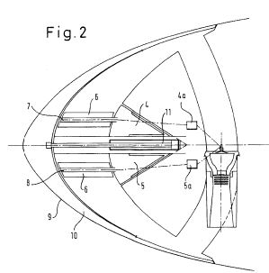
fuel. Dr Plichta has patented a turbine that would optimally
use the silicon-based combustion process.
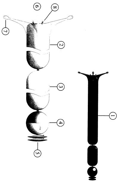
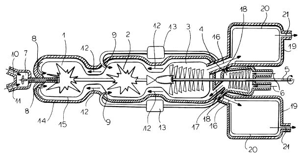
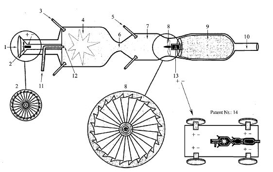
A mixture of silane oil (10) and silicon powder (11) are mixed
and injected by a pump (7) into the main combustion chamber.
There the fuel is burned together with pre-heated air (8). In
the secondary combustion chamber (2) the fuel mix is further
burned with a large amound to cold air (9), quickly lowering
the temperature of the gases from about 2000 degrees C to a
few hundred degrees. This brings a large pressure increase. If
the silicon nitride powder produced by the combustion process
were too hot and not diluted with air, it would destroy the
turbine blades.
The resulting mixture of gases (H2O, O2, and Si3N4 of oily
consistency) is now able, in the turbine chamber (3), to cause
the turbine blades to rotate. The rotation is transmitted over
a connected shaft (5) to the compressor chamber (4) where air
is aspired through air inlets (6). The air is mostly conducted
into the secondary combustion chamber (2) and a small part of
it goes, after heating, to the first combustion chamber (1).
The the absorption of heat by the air also provides needed
cooling of the combustion chambers.
The water vapor produced by the combustion process leaves the
turbine through exhaust openings (21) while the cooled down,
solid silicon nitride is trapped in dust bags (20), ready to
be passed on for later industrial uses.
Internal combustion engines of the Otto and Diesel type would
suffer breakdown of lubrication if made to burn silicon oils.
The temperatures of combustion are considerably higher than
those reached by gasoline or diesel. But according to Plichta,
the Wankel-type rotary piston motor could be modified to
accomodate the high temperatures. It parts would have to be
coated with silicon nitride ceramics or be entirely
constructed using the even harder silicon carbide.
The silane oils could not be compressed together with air,
they would have to be injected at the point of maximal
compression. The silicon nitride contained in the combusting
fuel/air mixture would initially be in gaseous and liquid
form, providing the necessary lubrification and acting as a
sealant. Exhaust gases, still very hot, could be further
burned in a turbine, with the addition of cold air as in the
second stage of Plichta's turbine design.
Like in the turbine, combustion in this engine would produce
small amounts of silicon nitride in powder form, which would
be filtered out from the exhaust gases and collected by
filling stations, to be passed on for industrial uses...
https://de.wikipedia.org/wiki/Peter_Plichta
Peter
Plichta

Peter Plichta (* 21. Oktober 1939 in Remscheid) ist ein
deutscher Chemiker, Apotheker und Autor.
Leben und
Wirken
Peter Plichta studierte Chemie in Köln, legte 1966 seine
Diplomprüfung ab und wurde 1970 mit einer Dissertation über
Silane („Präparative und spektroskopische Untersuchungen zur
Darstellung von Disilanyl- und Digermanylverbindungen und
Germaniumwasserstoffen“)[1] unter Franz Fehér[2] am Institut
für Anorganische Chemie der Universität Köln promoviert. 1977
erlangte er die Approbation als Apotheker.
Zu Plichtas technischen Konzepten gehört ein Fluggerät, das in
seiner Form einem Diskus ähnelt. Dieses Konzept soll nach
Plichta das heute übliche Mehrstufenantriebs-Prinzip in der
Raumfahrt ablösen, welches nur zur Beförderung sehr geringer
Nutzlasten (etwa 4 Prozent bei Ariane 5) in der Lage ist.
Seinem Buch Benzin aus Sand zufolge ist das „einstufige“
Erreichen der erdnahen Umlaufbahn möglich, weil der von
Plichta entdeckte Treibstoff (siehe unten) nicht nur in
Sauerstoff, sondern auch in Stickstoff brennt, und deshalb in
der Erdatmosphäre kein Oxidationsmittel mitgeführt werden
muss.
Peter Plichta hat in mehreren Ländern Patente auf einige
seiner Entwicklungen angemeldet, darunter in den USA. Sein
Entwurf wird von der Fachwelt abgelehnt. Bis heute wurde kein
ernstzunehmender Versuch einer Realisierung unternommen.
In den 1970er-Jahren begann Plichta, sich mit der
synthetischen Treibstoffgewinnung aus Silicium, insbesondere
aus Sand, zu beschäftigen. Plichta gibt an, als erster
stabile, längerkettige Silane synthetisiert zu haben. Trotz
Plichtas Veröffentlichungstätigkeit zu diesem Thema
(Hauptwerk: „Benzin aus Sand. Die Silan-Revolution“) blieben
seine Forschungen bisher ohne nachhaltige Resonanz in der
Fachwelt und bei Automobilherstellern. In einer der wenigen
Rezensionen des Werks in einer Fachzeitschrift wird Plichtas
Vorschlag der Silan-Revolution als „origineller Vorschlag“
bezeichnet und die Frage gestellt, ob dieser „… belastbar oder
gar seriös?“ sein könne. Das Buch informiere den Leser „… in
einer eigenartigen Mischung aus Selbstbewusstsein, verkanntem
Genie, Besserwisserei und Weinerlichkeit über selbstgewählte
Höhepunkte …“ und folge in seinen Deutungen einer dem
Rezensenten nicht zugänglichen Logik. Auch wenn nicht klar
würde, was das Werk solle, gehe ein gewisser Reiz davon
aus.[3]
Seit 1991 veröffentlicht Peter Plichta seine Überlegungen zu
seinem Weltbild. Er möchte dabei die physikalisch-chemische
Realität aufbauend auf zahlentheoretischen und
zahlenmystischen Überlegungen beschreiben, wobei insbesondere
Primzahlen eine wichtige Rolle spielen.[4] Er behauptet, mit
seiner Arbeit die Quantenmechanik obsolet gemacht zu haben:
„Diese Vorgehensweise ersetzt das ganze
Kartenhaus der modernen Naturwissenschaft, die
Quantenmechanik, durch exakte Mathematik. Deren Struktur ist
euklidisch und im Dezimalsystem, dem einzig möglichen
Zahlensystem der Natur, angelegt.“[5]
Plichta stellt den Anspruch, seine Theorie mathematisch
„bewiesen“[6] zu haben. Er schließt Indeterminismus damit
kategorisch aus:
„Für jede Theorie, die auf zufälligem
Geschehen aufbaut, ist mit einem Schlag das Ende eingeläutet.
Einstein muß es geahnt haben.“[6]
Die Urknalltheorie lehnt Plichta ab. Er vertritt eine
alternative Erklärung für die Bindung des Sauerstoffs ans
Hämoglobin im Blut.[7]
Die Chemiker Jan C. A. Boeyens und Demetrius C. Levendis haben
Plichta in ihrem Werk Number Theory and the Periodicity of
Matter referenziert. Ebenso wie Plichta versuchen sie die
moderne Quantenphysik durch elementare zahlentheoretische
Überlegungen zu ersetzen, im Gegensatz zu Plichta stellen sie
jedoch nicht die allgemeine Relativitätstheorie in Frage, in
der der Raum nicht euklidisch ist, und sehen keine
ausgezeichnete Rolle des Dezimalsystems (The specification of
common numbers in decimal notation is almost certainly a
remnant of counting practice using a ten-finger base[8]).
Peter Plichta trat seit 2011 mehrfach als Gesprächspartner
beim Alpenparlament.tv sowie 2013 beim Alpenparlament Kongress
auf.[7]
http://www.plichta.de/
Der Erfinder
und Entdecker
Dr. Peter Plichta, Jahrgang 1939, studierte Chemie, Physik,
Kernchemie und Jura an der Universität Köln. Promotion 1970
über Silanverbindungen, deren Darstellungen bis dahin als
unmöglich galten. Zu Beginn seiner Habilitation 1971 gelang
ihm die Gewinnung der Dieselöle von Siliziumwasserstoffen
(Höhere Silane). 1973 - 1976 Studium Pharmazie und Biochemie
an der Universität Marburg. Ab 1981 Privatgelehrter auf den
Gebieten Logik, Zahlentheorie und Mathematik. Zu diesem
Zeitpunkt löste er das geometrische Problem der 4. Dimension
aus der Verteilung der Primzahlen. Der Raum um einen Atomkern
ist schalenförmig und von der Form zweier sich durchdringender
Flächen und besitzt die Dimensionen Länge hoch 4. Damit war
die Verknüpfung der 3 Dimensionen des Raumes mit einer
eindimensionalen Zeit als eine geistige Fehlentwicklung
entlarvt. 1991 Veröffentlichung der ersten beiden Bücher "Das
Primzahlkreuz" Band I und II.
http://www.plichta.de/plichta/siliziumzeitalter
http://www.plichta.de/media/Benzin_aus_Sand.pdf
Raum &
Zeit : "Benzene from Sand"
[ PDF ]

https://worldwide.espacenet.com/advancedSearch?locale=en_EP
Silane
Patents by Plichta
DE102007058654
Cyclic
production of silicon or silicon compounds and hydrogen...
A cyclic method for production of crystalline silicon (Si),
silane, silicon nitride or carbide and hydrogen (H 2) is based
on pyrolysis of oil-containing sand or shale (I) (as mixture
of hydrocarbons and silicates), contaminated with potassium
aluminum silicate and carbonate. Released H 2is heated with
fluorine to give hydrogen fluoride, which is reacted with the
Si of (I) to give silicon tetrafluoride for conversion into Si
by thermite methods using aluminum. Cyclic production of
crystalline silicon (Si), silane, silicon nitride or carbide
and hydrogen (H 2) involves pyrolyzing oil-containing sand or
shale (I) (as mixture of hydrocarbon energy source (tar) and
silicates (SiO 2)), contaminated with potassium aluminum
silicate and carbonate, at more than 2000[deg] C. The released
H 2is fed into a gas main or heated at ca. 4000[deg] C with a
specific amount of fluorine (F 2) to give hydrogen fluoride
(HF). The hot HF is immediately reacted with the Si of (I) to
give silicon tetrafluoride (SiF 4) gas and water vapor; and
the hot SiF 4(contaminated with HF) is fed directly into a
combustion chamber supplied continuously with aluminum (Al)
powder, in which SiF 4is converted into high purity
crystalline Si by a thermite process. The obtained Al fluoride
(AlF 3) powder (stable towards aqueous base) is filtered off
before electrolytic conversion (in hexafluorosilicate form)
into more Al and F 2. The necessary DC current is permanently
obtained using process heat; the thermite process
stoichiometrically releases 1172 KJ of energy per unit time
and cooling with preheated water gives steam for AC
generation. Heat from SiF 4production is also used for
electricity generation. In the pyrolysis stage, the SiF 4-H 2O
mixture is passed into the center of an Al powder-filled
rotating drum with a welding flame in the cylinder center, and
heat conduction causes exponential decrease of high
temperatures in the cylinder wall direction (as in the
subsequent thermite process). Cooling of the double-walled
drum with water allows generation of a large amount of
current, and Al and F 2are recycled to the cyclic process.
DESCRIPTION
Cyclic large-scale production of crystalline silicon /
photosilicon or the fuel silane or the ceramics silicon
nitride or silicon carbide and very large amounts of gaseous
hydrogen from oily sands / slags using aluminum and the
mixture of fluorine and hydrogen which provides 4,000 ° C hot
hydrogen fluoride on combustion , Is carried out in such a way
that the welding flame temperature only pyrolytically cleaves
the stoichiometric content of the oil / tar content into
graphite and hydrogen and is achieved by means of a device in
which the vessel wall is heated only to about 400 ° C.
The stocks of oil-bearing sands (SiO2) and slate (SiO2 + [CO3]
<2>) are, as is well known, much higher than the world
oil reserves. The technical processes used to separate oil and
minerals are inefficient and too expensive.
The combustion products required to generate heat generate
CO2. So far, it is only in patent application 10 2006 023
515.0 that mention is made of the use of the sand present in
the mixtures as energy carriers and to extract new raw
materials from the products, whereby the oil pitch present in
the sands and obliques itself becomes a supplier of gaseous
hydrogen.
The object of the present invention is to provide a cyclic
process in which only a certain amount of fluorine and
aluminum is used in addition to the oil sand / shale. This
amount is constantly recycled, as will be explained below. In
fact, only as much silicate is to be converted into silicon
fluoride, as is available per primary unit of oil / tar as
primary energy. In this procedure, for example, as with an
Archimedean screw, oil sand / shale or a mixture of sand and
waste oils, Strongly sulfur-containing petroleum is passed
through a rotating stainless steel boiler. The burner
arrangement is located in the center of the vessel so that the
enormous heat of almost 4,000 ° C decreases exponentially
during the rotary movement of the sands to the outer vessel
spacing. It is thereby achieved that the boiler wall which is
coated with hard metal, which is not attacked by gaseous
hydrogen fluoride, is supplied with little heat. The liberated
heat can be converted into electrical current via the
generation of water vapor via a turbine.
The mixture of silicon fluoride, hydrogen and carbon dioxide
is now passed into a second vessel, in which
stoichiometrically enough aluminum granules are fed per unit
of time, so that, as above, the gas mixture is fed back into
the middle via a rotating drum. The resulting termite reaction
produces so much heat that the double-walled boiler must be
cooled with water. This generates so much electrical current
that the amounts of current can be used for the electrolysis
of the aluminum fluoride. Here, the ALF 3 is admixed with
potassium fluoride, so that potassium aluminum hexafluoride is
formed. The cryolite thus obtained can be melted with purified
bauxite and used to obtain aluminum. The object of the
invention is also to recover electrolytically the fluorine
used in copper boilers. The amounts of current for recovering
the fluorine and aluminum used can be achieved via the
three-phase current generators.
The hydrogen gas required for the application can be removed
from the hydrogen produced.
Overall, the primary energy of the oil / tar provides so much
heat and hydrogen that 100% recycling of the fluorine and
aluminum is ensured.
The crystalline silicon obtained is chemically very pure. The
large amounts of hydrogen can be used for the production of
aluminum, whereby no CO 2 is liberated when hydrogen is burnt,
while today the aluminum plants work with brown coal. The
remaining hydrogen is chemically separated from the carbon
dioxide and can be fed into existing gas networks instead of
natural gas, which burns to carbon dioxide.
Since 40 billion tons of oil shale are stored in Jordan alone,
the process described here can be used to produce photosilicon
at incredibly low prices. At the same time, the process can be
coupled with an aluminum production. The cleaning of bauxite
and silicate, which has hitherto been carried out, can be
carried out very simply in a further patent chemically.
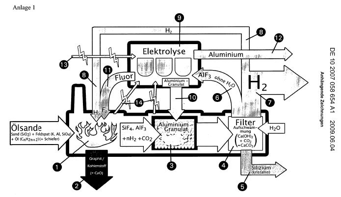
The cyclic process is now to be explained in more detail
chemically by several digits. Annex 1 shows a series of
large-scale production plants, which begin with the fact that
oily sands / shale are transported to the decomposition plant
I on mechanical transport routes.
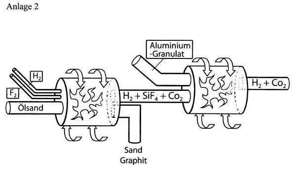
Annex II shows the points 1 and 3 of Annex I schematically. 1)
With patent (a) DE 21 53 954 and (b) DE 195 33 765, it is
known that, when the fluorine is hydrogenated with hydrogen,
the hydrofluoric silicatified rock formed is completely
converted into gaseous components SIF4, AlF3 (see a) The
resulting silicon fluoride is rendered harmless with sodium
hydroxide solution in this process (see b). 2) Oil-containing
sands can be treated with the very hot hydrogen fluoride (over
3,000 ° C) formed during combustion, so that silicon fluoride
is produced in the main (one, one). A lot of heat is released.
3) The heat pyrifies the involved oil pitch to carbon /
graphite, which can be removed from the process (two, two). If
slate is present, calcium oxide CaO is also created to be
reused elsewhere. 4) The gaseous SiF 4, possibly contaminated
by AlF 3 and traces of potassium fluoride and other metal
fluorides, is now transferred together with the large amounts
of hot hydrogen gas to (3, 3).
There, it is mixed with aluminum granules (10, 10) by the
Thermit method in the form of the salt SiF4 · 2KF = K2 [SiF6]
according to the equation 3SiF4 + 4Al? 3Si + 4AlF3 + 1172.7 kj
is converted into crystalline silicon by evaporation of air.
The heat liberated in (1, 1) and (3, 3) can be withdrawn from
the system by the production of hot water vapor by built-in
cooling coils and converted into three-phase current
(fourteen, 14). 5) The mixture of crystalline silicon, AlF 3
and H 2 arriving in (4, 4) is free of CO and CO2, since the
process is carried out under airtight conditions. If the pitch
oil mixture contains shale, CO2 is formed next to calcium
oxide, which is separated in (4, 4) in aqueous solution with
calcium hydroxide. The CO2 can thus be bound as calcium
carbonate with the CaO obtained in (2, 2) and removed from the
system. 6) The main quantity of hydrogen is fed into existing
heating gas pipeline systems (seven, 7), while the
stoichiometric quantity of H2 required for the circuit is fed
back via a line (8, 8) (one, one).
7) The dried, powdered AlF3 (insoluble in water and lye) freed
from the water by filter pressing is subjected to melt flow
electrolysis (9, 9). For this purpose, the stream produced
with the self-produced hydrogen will be used (thirteen, 13).
In addition, there are bundled streams (fourteen, fourteen)
(one, one) and three (three). 8) The aluminum (ten, 10)
resulting from the electrolysis will largely be cyclically
reused in (3, 3). The unused part of the aluminum can be
removed. The resulting F2 (eleven, 11) is used again without
loss in (one, 1). 9) In the equation under no. 4) there are 3
moles of silicon on the right side as well as 1172 kj. At
present, crystalline silicon is represented by an elaborate
process using coal, high electrical costs and fractionating
chlorosilanes with subsequent pyrolysis. The price is very
high, since it is agreed worldwide. The new cyclic process
would reduce the kilo price for photosilicon to one
hundredths.
10) If desired, this crystalline silicon can be converted
directly to pure silicon nitride by ignition with pure cold
nitrogen, since the reaction is strongly exothermic. (Si3N4 is
a solid noble gas [Plichta]. ) The most important ceramics
used in the art - Silicon nitride (with its remarkable thermal
conductivity) and silicon carbide (with its diamond-like
hardness) Can be obtained in this way, since the very pure
carbon from (2, 2) can also be used here. 11) The available
crystalline silicon is surface active and could be
catalytically treated with hydrogen to form monosilane. This
monosilane can be removed from the reaction chamber and
converted into long-chain silanes in a further patent
application. These are not only to be used in space travel
because they supply atomic hydrogen in the heat (Plichta). The
atomic hydrogen can also be used in a fuel cell, which can be
inferred from an additional patent application.
12) The heat generated in (1, 1) and (2, 2) and (4, 4) is, as
discussed above, so low that it can be used to produce
electricity. In general, the use of open-cast oil sands and
slate is so high that it can be compared with the combustion
of coal, lignite and natural gas, with the scouring of fossil
deposits and the emission of carbon dioxide from electricity
factories And vehicles as irresponsible. Only the use of
low-cost solar cells can be referred to as "perpetuum mobile"
when low-cost silane gasoline is subjected to a nitrogen
cycle, in which ammonia is produced by the production of Si3N4
and its cleavage, which produces electricity during combustion
Nitrogen back into the atmosphere. (Plichta)
DE10059625
Production
of long-chain silanes for use as fuels comprises
performing a modified Muller-Rochow synthesis with
monochlorosilanes, partially methylated monochlorosilanes
or monofluorosilane
The present invention relates to a plurality of processes for
producing higher silanes, in particular with regard to the
inexpensive recovery and use as fuels.
The decomposition of magnesium silicide with acids produces
hydrogen and monosilane. The yield of the liquid silanes tri-
and tetrasilane is approx. 5%.
It is known from patent 21 39 155 to obtain higher silanes by
pyrolysis of tri-, tetra- and pentasilane. Higher silanes are
non-toxic, since heptasilane is no longer self-igniting and
thus safe to handle. Such higher silanes can be used as a
propellant according to patent specification 44 37 524 in that
they are combusted with atmospheric air. In hot combustion
chambers, silanes decompose into free silicon atoms which
react with the air nitrogen, which is considered inert, to
form silicon nitride Si3N4. The hydrogen content of the silane
reacts with the air oxygen to water. Both reactions provide
energy. In order to burn the air nitrogen completely, it is
also known, as disclosed in Patent Specification No. 196 12
507, to add silanol, additionally dispersed silicon powder or
dispersed metal silicides, which also react with the air
nitrogen with heat dissipation.
For example, the stoichiometric combustion equation for
heptasilane is Si7H16 with air consisting of 20% oxygen and
80% nitrogen: 16H + 4O2? 8H2O; 7 Si + 16 N2 + 17 dispersed Si?
8 Si3N4.
SUMMARY
OF THE INVENTION
The object of the present invention is to produce higher
silanes or partially methylated higher silanes inexpensively
and in high yields and to remedy the disadvantages of the
prior art. As a basic substance, silicon compounds that are
already being used in industry in large scale, such as, for
example, Mono- or disilane, or mono- or disilane Disilanes
with different methyl groups or chlorine residues. The use of
fluorosilanes is also advantageous since these can be prepared
directly from SiO 2.
Method I
(Modified Müller-Rochow synthesis)
The object is achieved according to the invention by the fact
that silicon powder is contaminated with catalysts, and is
reacted under pressure and heat with silyl chlorides or
disilyl chlorides or methylated silyl or disilyl chlorides.
According to the conventional Mueller-Rochow synthesis, methyl
chloride CH3Cl is reacted with powdered silicon in the
presence of copper / copper oxide as catalyst to give
methylchlorosilanes. 80% of dimethyldichlorosilane (CH3)
2SiCl2 is formed, followed by (CH3) SiCl3 (10-15%) and other
methylchlorosilanes.
(A) It is proposed to first modify the Müller-Rochow synthesis
in such a way that the methyl chloride is replaced by silyl
chloride. SiH3Cl can be obtained from tetrachlorosilane SiCl4
by hydrogenation. On the other hand, it can also be
catalytically chlorinated with HCl according to Alfred
Stockmonosilan. Silyl chlorides, however, are generally used
as waste products in silicone chemistry.
Thus, silicon powders with catalysts such as copper / copper
oxide are reacted under pressure and heat with silyl chloride
to give disilyldichlorosilane (SiH3) 2SiCl2 (a trisilane).
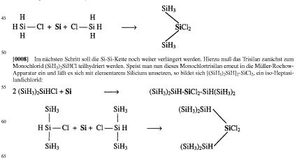
The next step is to extend the Si-Si chain even further. To
this end, the trisilane must first be partially hydrogenated
to the monochloride (SiH 3) 2SiHCl. If this
monochlorotrisilane is again introduced into the
Miiller-Rochow apparatus and allowed to react with elementary
silicon, [(SiH3) 2SiH] 2-SiCl2 is formed, an iso-heptasilane
dichloride:
The chlorine atoms can then be easily hydrogenated so that
(SiH3) 2SiH-SiH2-SiH (SiH3) 2, a pure iso-heptasilane.
It is, of course, possible to introduce the heptasilane
hydrogenated into the monochlor form once more into the
Miiller-Rochow synthesis so as to obtain a Si15H30Cl2 or
hydrogenation Si15H32 after hydrogenation.
It is obvious that other metals / metal oxides could also be
used as catalysts. The possibility of using silanichloride SiH
2 Cl 2 or even SiHCl 3 as the starting product is also to be
covered by the process described here.
Instead of chlorosilanes, fluorosilanes such as SiH 3 F could
also be used. The advantage is that this material can be
obtained directly from sand or rock, so that smaller amounts
of expensive elementary silicon are needed. For this purpose,
SiO 2 is mixed with hot hydrogen fluoride gas or alternatively
with hydrofluoric acid / conc. Sulfuric acid mixture, SiF4
being formed. Chlorofluorides such as ClF 3 can also be used,
whereby silicon fluorofluorides such as SiClF 3 are formed.
These resulting fluorides, ie, SiF 4 or SiClF3, can now be
hydrogenated to mono- or di-fluoroform analogously to the
procedures described with chlorosilanes at the beginning of
this section and fed into the Rochow synthesis.
The processes described in paragraphs 1b), c), d) and method 2
also work with the corresponding fluorides as well as with
chlorides.
B) Disilan monochloride Si2H5Cl could also be used. This
substance is obtained from hexachlorodisilane Si2Cl6 by
hydrogenation. (Si2Cl6 itself is prepared from
tetrachlorosilane SiCl4. ) In this case, the main product is
dis-disilyldichlorosilane (Si2H5) 2SiCl2, a
dichloropentasilane.
Further, an industrial waste product, such as a disilane
containing both chloro atoms and methyl groups, could again be
used. A silane of this kind is then hydrogenated to a form in
which it contains only one chlorine atom, in order
subsequently to employ the Miiller-Rochow synthesis. In the
case of a disilane, a dichloropentasilane with methyl
substituents is formed. One of the two chloro atoms can then
be hydrogenated, so that the Müller-Rochow synthesis can be
used once more. The result is an undecasilane, the methyl
groups of which are of little importance when used as a fuel.
As in FIG. 1a), it is also possible here to directly use a
partially methylated chlorosilane with two or even several
chlorine atoms.
C) The chlorosilanes described in 1a) or 1b) can also be
dimerized or cyclized directly with alkali metals such as
lithium or alkaline earth metals such as magnesium. One of the
two free chlorine atoms on the central silicon atom can also
be hydrogenated and the dimerization can then be carried out.
The higher silanes (SiH3) 2SiH - SiH (SiH3) 2, a hexasilane,
or the (Si2H5) 2SiH - SiH (Si2H5) 2, a decasilane can thus be
used as a propellant in the form of a non - ignitable mixture.
Even higher cyclic compounds such as substituted pentasilanes
are, of course, not self-ignitable.
D) The chlorosilanes obtained by (1a) and (1b) could also be
chain-extended by pyrolysis, as described in pure silanes, as
described in German Patent 31,315,155. Subsequently, the
thus-obtained substance would be hydrogenated to obtain a pure
silane.
Method 2
The object is achieved according to the invention by the fact
that silicon tetrachloride SiCl 4 or hexachlorodisilane Si 2
Cl 6 is hydrogenated either by lithium hydride, if possible by
hydrogen pressure hydrogenation on the catalyst, so that mono-
or Disilane is formed. It can, of course, also be based on
mono- Disilane, which are obtained as gaseous products in the
case of the Cane acid decomposition, and are usually flaked
off.
These two silanes, in turn, are then reacted with liquid
sodium-potassium alloys in higher ethers, so that the
monosilane, potassium silyl, is SiH3K, from the disilane
potassium disilyl Si2H5K. The filtered solutions contain the
two potassium compounds in liquid form. Both attack
chlorosilanes, whereby KCl precipitates. The iso-octasilane
(SiH3) 3Si-Si (SiH3) 3 is formed from hexachlorodisilane from
tetrachlorosilane, for example, from the tetrachlorosilane,
the longer-chain iso-pentasilane.
It is also proposed to replace the above-described modified
Müller-Rochow synthesis and the chain extension with potassium
silane compounds in the course of the preparation of
longer-chain silanes.
This is done with the intention of allowing continued chain
extensions. If the chlorosilanes are treated with too large a
quantity of potassium silyl, then all the chlorinatoms with
the potassium combine to form KCl, and further chain
lengthening is impossible. If, however, the potassium silane
is added in a lesser quantity, the chlorosilanes formed still
contain some, and in the ideal case a chlorine atom. This
allows the Müller-Rochow synthesis to be used again for chain
elongation, and then again to carry out chain lengthening by
potassium silyl.
DE2139155
Synthesis
of higher silanes and higher germanes
Crude tri-, tetra- and penta-silanes are vaporised under high
vacuum in a boiler heated with warm water, passed through a
vertical Pyrex column packed with glass wool catalyst and
heated by external electrical heating elements, the products
being collected in a receiver at the top of the column cooled
to -196 degrees C. The mixed products are fractionated by
vapour phase chromatography at 220 degrees C. To produce up to
7-Si chains (n- and iso-heptasilane) the column is run at 420
degrees C, for 8-si chains at 410 degrees C, for 9-Si chains
at 360 degrees C, and for 10-Si chains with a glass
wool-silica gel-platinum (5%) catalyst at 410 degrees C. For
the prodn. of higher germanes from trigermane the column is
run at 300 degrees C. The fractionated higher silanes are
diluted with benzene and frozen at -80 degrees C for storage.;
To increase yields the pyrolysis is repeated several times by
deep cooling the original boiler and heating the original
receiver, and vice-versa.
The invention relates to a process for the preparation of
higher silanes by pyrolysis of trisilane, n-tetrasilane and /
or n-pentasilane and of higher germanes by pyrolysis of
Trigerman.
The device further relates to a device for carrying out said
method.
It is known that, in the decomposition of magnesium silicide
with loic hydrochloric acid, not only silicon-hydrogen but
also higher silanes are formed, which can be fractionated as a
liquefied mixture in the high vacuum into the individual
constituents.
This is the classical Stock method, in which the following
reactions have obtained some significance for the preparation
of higher silanes: the pyrolysis of low silanes; The effect of
silent electric discharge on low silanes; The pyrolysis of
(SiF2) X with aqueous hydrofluoric acid; The hydrogenation of
perchlorosilanes and the reaction of halosilanes with
potassium silyl. None of these methods has so far led to the
preparation of higher silanes with chain lengths of more than
6 silicon atoms.
In addition, the technical yield of higher silanes is low in
the known processes.
The object of the invention is to produce higher silanes, even
with chain lengths of more than 6 silicon atoms, at a high
yield. Moreover, the object of the invention is to prepare
higher germanes from the starting substance Trigerman and to
remedy the disadvantages of the prior art with regard to the
production of higher silanes and germanenes.
The object is achieved according to the invention by the fact
that the starting silane or Is vaporized in the high vacuum,
the starting / German on a glass wool contact at a temperature
in the range from 360 C to 420 C or
Is pyrolyzed below 300 ° C. for the production of higher
germanes, then the decomposition products are condensed and
converted gaschromatically into individual higher silanes or
Germane.
According to the method according to the invention, it is
possible to present higher silanes and germans in a
comparatively simple manner with high yield. Moreover, it was
found that, unlike previous views, the higher silanes are
stable with more than six silicones, and pure heptasilane is
not self-ignitable in the presence of air, 1 as has always
been assumed. This opens up new possibilities for technology.
For the preparation of iso-tetrasilane, isa-pentasilane, n-
and iso-hexasilane and n- and iso-heptasilane, it is
preferably proposed to use trisilane as the starting substance
and to carry out the pyrolysis at a temperature of
4200.degree. This is used as the main product to produce n-
and iso-pentasilane Si5H12.
It is important that iso-tetrasilane is also formed as 5-loX.
For the preparation of especially n- and iso-heptasilane
Si7H16, according to a further proposal of the invention,
n-tetrasilane is to be used as the starting silane and the
pyrolysis is carried out at a temperature of 410 ° C. In order
to arrive at a main product n- and iso-octasilane Si8H18,
n-pentasilane is used as starting silane in a suitable
embodiment of the invention and the pyrolysis is carried out
at a temperature of 3600.degree.
The pyrolytic decomposition of n-tetrasilane on the glass wool
silica gel platinum contact, preferably on a glass wool silica
gel platinum (5 ff) contact, even results in the preparation
of decasilane.
The production process according to the invention includes, as
the last process step, the gas-chromatographic separation into
individual higher silanes or Germane. The gas chromatographic
separation is preferably carried out at a temperature of about
220 ° C., in which the straight-chain silanes can be separated
well from their isomers. The condensation of the silane of the
German steam prior to the gas chromatographic separation is
preferably carried out at a temperature of -1960.degree.
Silanes with chain lengths of six to ten silicon atoms are
oily, colorless liquids. While hexasilane Si6H14 spontaneously
ignites spontaneously in the air, gaseous pure heptasilane is
no longer self-igniting and first flames with the aid of a
catalyst, B. Cellulose paper. Higher silanes are much more
stable than previously thought. This shows their preparation
at temperatures around 400 ° C. and their gas chromatographic
separation at a temperature of 220 ° C.
At room temperature, higher silanes decompose after standing
for a long time with the deposition of white flakes. Such
abundant quantities spontaneously flinch in air, which is due
to the formation of low silanes. This can be proved by gas
chromatography. In a further embodiment of the invention, it
is therefore proposed to dilute the products with absolute
benzene for the purpose of storing the higher silanes and
subsequently to freeze the solutions at a temperature of
-8.degree. The benzene is easily separated off by gas
chromatography if this is again necessary.
To increase the yield of higher silanes, the pyrolysis can be
repeated several times, with heating baths being ensured that
the higher silanes formed are not thermally decomposed a
second time.
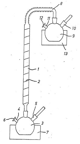
According to the invention, the apparatus for carrying out the
described process for the production of hydraulic silanes or
germanics is characterized in that a heatable pyrex tube
filled with glass wool is provided, one open end of which is
connected to a container for receiving the starting silane or
geranium And the other end of which opens into a condenser
which is coolable to a temperature of 1980 ° C by means of a
cooling unit, and that the vessel and the condenser are
connected to a high vacuum system and are provided with
pressure-tight openings for filling and / The starting
substances used for carrying out the process according to the
invention trisilane, n-tetrasilane, n-pentasilane and
trigerrnane can be prepared in a known manner. The starting
substances thus obtained are treated according to the method
according to the invention in the apparatus described below,
which is schematically illustrated in the drawing. The
essential element of the apparatus suitable for carrying out
the process, which is shown in the drawing, is a pyrolysis
column consisting of a pyrex tube 1, which is filled
internally with glass wool as filling material.
The pyrex tube 1 is suspended essentially vertically and is
surrounded by a heating device which is capable of producing
temperatures of more than 420 degrees Celsius inside the pyrex
tube 1. In the exemplary embodiment, the heating device
consists of an outer winding 2 consisting of heating strip
(asbestos and electrically conductive wires), which extends
almost over the entire length of the pyrex tube 1. With its
lower end, the pyrex tube 1 is connected to a glass flask 3,
which is a container for receiving the starting silane or
gander. The connection is designed to be highly vacuum tight
by means of a corresponding cut.
The glass flask is provided with two openings 4, 5, one of
which is for connection to a vacuum chamber and the other is
vacuum-tightly closed by means of a known rubber cap, which is
made of a material which prevents the filling and emptying of
the glass flask 3 by means of a syringe- Without the risk of
access to external atmosphere. The connection of a @
Oueckilber steam jet pump to the opening 5 of the glass bulb 3
is indicated in the drawing by an arrow. The schematically
illustrated rubber cap is provided with the reference numeral
6.
The glass flask 3 is surrounded by a Dewar vessel 7, which is
suitable for receiving a heating bath or liquid nitrogen.
A substantially similar arrangement is located at the upper
end of the pyrex tube 1. A glass bulb 9 is also vacuum-tightly
connected to the pyrex tube 1 via a glass tube line 8, which
is surrounded by insulating material. The glass flask 9 has an
opening 10 with which the vacuum chamber can be connected and
an opening 11 for filling and emptying the glass flask 9,
which is provided with a through-cut cap 12 corresponding to
the rubber cap 4. The glass flask 9 is arranged within a Dewar
vessel 15 which can be filled with a heating bath or liquid
nitrogen. For the preparation of the silanes used, a robust
mixture is prepared by decomposing magnesium silicide with
aqueous phosphoric acid, which is separated by preparative gas
chromatography. The process is carried out with the utmost
exclusion of oxygen and moisture in an atmosphere of
ultra-fine nitrogen in the apparatus described. First, hot
water is filled into the Dewar vessel 7 and the starting
silane is filled into the glass flask 5 by means of a syringe
.
Liquid nitrogen is then introduced into the Dewar vessel 15 to
build up a condenser at the upper end of the pyrex tube 1.
The high vacuum pump, which is connected to the opening 10 of
the glass bulb 5, is adjusted and maintains a high vacuum in
the apparatus. At the same time, the heating is switched on by
applying a voltage to the coil 2 of the heating coil. The
result of this is that the starting fluid evaporates and rises
through the pyrex tube 1 filled with glass wool. Pyrolysis
takes place. The pyrolysis product condenses in the glass
flask 9, that the glass flask 9 now has a content, while the
glass flask 3 is emptied.
Subsequently, aeration of the apparatus to atmospheric
pressure with nitrogen takes place, and the Dewar vessel 7 is
filled with liquid nitrogen, in order to remove a condenser at
this point. Analogously, the Dewar vessel 15 is filled with
hot water and the high vacuum is built up through the opening
5 of the glass bulb 5. The reverse process takes place as
described above, and a new pyrolysis takes place. This process
is repeated up to 8 ×, it being pointed out that the higher
silanes which are formed do not pyrolyze again since they have
a higher boiling point. At the end of the process, the higher
silanes shown are placed in the glass flasks 5 and 9 in
approximately the same amount. They are removed through
openings 4 and 11 and fed to the gas chromatographic
separation.
In the case of pyrolysis, additional products are hydrogen,
monosilane and disilane. During the reaction, the hydrogen is
withdrawn continuously from the mercury vapor jet pump of the
high vacuum system, and the monosilane and the disilane are
also removed after each reccondensation.
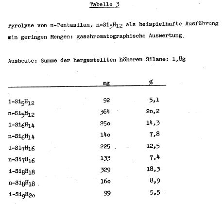
In carrying out the process according to the invention, the
quantitative compositions described in Table 1, Table 2 and
Table 3 were prepared, for example, on higher silanes. In the
pyrolysis of n-tetrasilane on a glass wool-silica gel platinum
(5%) contact, n- and iso-decasilane Si101122 was prepared. The
iso-decasilane is a clear paraffin-like oil.
The gas chromatographic separation of the pyrolysis products
can be carried out with the known, known devices. The
substances are collected by means of an injection needle,
which is soldered to the gas-chromatographic outlet, in
collecting tubes with rubber caps and V2A taps in order to
reduce the risks when working with self-igniting substances.
In the pyrolysis of Trigerman Ge3H8 according to the method
according to the invention, n-tetragerman Ge4H10,
iso-tetragerman i-Ge4H1O, iso-pentagerman i-Ge5H12 and
n-pentagerman Ge 012 are produced, where n-tetragerman is the
main product. As a working temperature, a temperature of less
than 3000 ° C. is preferred in carrying out the pyrolysis of
Trigerman. At this temperature higher germans can be produced
with high yield than at temperatures above 3000 ° C., in which
the decomposition into germanium and hydrogen predominates.
TABLE 1
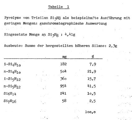
TABLE 2
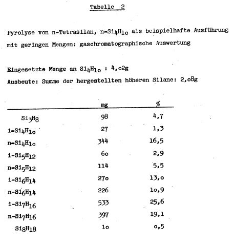
TABLE 3
WO0244085 /
AU2344702
METHOD
FOR PRODUCING HIGHER SILANES TO BE USED AS FUEL
Process for the preparation of higher silanes with regard to
their use as propellants The present invention relates to a
plurality of processes for preparing higher silanes, in
particular with regard to the inexpensive recovery and use as
fuels.
The decomposition of magnesium silicide with acids produces
hydrogen and monosilane. The yield of the liquid silanes tri-
and tetrasilane is approx. 5%.
It is known from patent 21 39 155 to obtain higher silanes by
pyrolysis of tri-, tetra- and pentasilane. Higher silanes are
non-toxic, since heptasilane is no longer self-igniting and
thus safe to handle. Such higher silanes can be used as
propellant according to patent specification 44 37 524 in that
they are combusted with atmospheric air. In hot combustion
chambers, silanes decompose into free silicon atoms which
react with the air nitrogen, which is considered inert, to
form silicon nitride Si3N4. The hydrogen content of the silane
reacts with the air oxygen to water. Both reactions provide
energy. In order to burn the air nitrogen completely, it is
also known, as disclosed in Patent Specification No. 196 12
507, to add silanol, additionally dispersed silicon powder or
dispersed metal silicides, which also react with the air
nitrogen with heat dissipation.
For example, the stoichiometric combustion equation for
heptasilane is Si7Hl6 with air consisting of 20% oxygen and
80% nitrogen: 16H + 4028H20; 7 Si + 16 N2 + 17 dispersed Si
Si4N4.
SUMMARY
OF THE INVENTION
The object of the present invention is to prepare higher
silanes or partially methylated higher silanes inexpensively
and in high yields and to remedy the disadvantages of the
prior art. As a basic substance, silicon compounds that are
already being used in industry in large scale, such as, for
example, For example mono- or disilane, or mono- or disilane.
Disilanes with different methyl groups or chlorine residues.
The use of fluorosilanes is also advantageous because these
can be prepared directly from SiO 2.
Method I
(modified Müller-Rochow synthesis)
The object is achieved according to the invention by the
fact that silicon powder is contaminated with catalysts and is
reacted under pressure and heat with silyl chlorides or
disilyl chlorides or methylated silyl or disilyl chlorides.
According to the conventional Mueller-Rochow synthesis, methyl
chloride CH3Cl is reacted with powdered silicon in the
presence of copper / copper oxide as catalyst to give
methylchlorosilanes. 80% of dimethyldichlorosilane (CH3)
2SiCl2 are formed, followed by (CH3) SiCl3 (10-15%) and other
methylchlorosilanes. A) It is proposed to first modify the
Müller-Rochow synthesis in such a way that the methyl chloride
is replaced by silyl chloride. SiH3C1 can be obtained from
tetrachlorosilane SiCl4 by hydrogenation. On the other hand,
it can also be catalytically chlorinated with HCl according to
Alfred Stockmonosilan.
Silyl chlorides, however, are generally used as waste products
in silicone chemistry.
Thus, silicon powders with catalysts such as copper / copper
oxide are reacted under pressure and heat with silyl chloride
to give disilyldichlorosilane (SiH3) 2SiCl2 (a trisilane).
<Img class = "EMIRef" id = "013737427-00020001" />
The next step is to extend the Si-Si chain even further. For
this purpose, the trisilane must first be partially
hydrogenated to the monochloride (SiH 3) 2SiHCl.
If this monochlorotrisilane is again introduced into the
Miiller-Rochow apparatus and allowed to react with elemental
silicon, [(SiH3) 2SiH] 2-SiCl2 is formed, an iso-heptasilane
dichloride: <img class = "EMIRef" id = "013737427-00020002"
/>
Subsequently, the chloro atoms can be easily hydrogenated so
that (SiH3) 2SiH-SiH2-SiH (SiH3) 2, a pure iso-heptasilane.
Of course, it is possible to feed the heptasilane hydrogenated
into the monochlor form once again into the Müller-Rochow
synthesis, so that a sil5H30C12 or hydrogenation silsH32 is
obtained.
It is obvious that other metals / metal oxides could also be
used as catalysts. The possibility of using silanichloride
SiH2C12 or even SiHCl3 as the starting product is also to be
covered by the process described here.
Instead of chlorosilanes, fluorosilanes such as SiH 3 F could
also be used. The advantage is that this material can be
obtained directly from sand or rock, so that smaller amounts
of expensive elementary silicon are needed.
For this purpose, SiO 2 is mixed with hot hydrogen fluoride
gas or alternatively with hydrofluoric acid / conc. Sulfuric
acid mixture, SiF4 being formed. Chlorofluorides such as C1F3
can also be used, whereby silicon chlorofluorides such as
SiCIFs are formed. These resulting fluorides, ie, SiF 4 or
SiCIFs, can now be hydrogenated to mono or di-fluoroform
analogously to the procedures described with chlorosilanes at
the beginning of this section and fed into the Rochow
synthesis.
The processes described in paragraphs (Ib), (c), (d) and
Method 2 also work with the corresponding fluorides as well as
with chlorides. B) Disilane monochloride Si2H5C1 could also be
used.
This substance is obtained from hexachlorodisilane Si2C16 by
hydrogenation.
(Si2Cl6 itself is prepared from tetrachlorosilane SiCl4. ) In
this case, the main product is dis-disilyldichlorosilane
(Si2H5) 2SiC12, a dichloropentasilane.
Further, an industrial waste product, such as a disilane
containing both chloro atoms and methyl groups, could again be
used. A silane of this kind is then converted by hydrogenation
to a form in which it contains only one chlorine atom, in
order to subsequently employ the Miiller-Rochow synthesis. In
the case of a disilane, a dichloropentasilane with methyl
substituents is formed. One of the two chloro atoms can now be
hydrogenated so that the Müller-Rochow synthesis can be
applied once more. The result is an undecasilane, the methyl
groups of which are of little importance when used as a fuel.
As in 1a), it is also possible here to directly use a
partially methylated chlorosilane with 2 or even several
chloro atoms. C) The methods described in la) and Ib) can also
be dimerized or cyclized directly with alkali metals such as
lithium or alkaline earth metals such as magnesium. One of the
two free chlorine atoms on the central silicon atom can also
be hydrogenated and the dimerization can then be carried out.
The higher silanes (SiH3) 2SiH-SiH (SiH3) 2, a hexasilane, or
the (Si2H5) 2SiH-SiH (Si2H5) 2, a decasilane can thus be used
as a propellant in the form of a non-ignitable mixture. Even
higher cyclic compounds such as substituted pentasilanes are,
of course, not self-ignitable. D) The chlorosilanes obtained
by 1a) and / or lb) could also be chain-extended by pyrolysis,
as described in pure silanes, as described in German Patent
No. 31 39,155. Subsequently, the thus obtained substance would
be hydrogenated to obtain a pure silane.
Method 2: The object according to the invention is achieved by
hydrogenating silicon tetrachloride SiC14 or
hexachlorodisilane Si2Cl6 either by means of lithium hydride,
but preferably by hydrogen pressure hydrogenation on the
catalyst, so that mono-
Disilane is formed. It can, of course, also be used on mono or
multi- Disilane, which are obtained as gaseous products in the
case of the Cane acid decomposition, and are usually flaked
off.
These two silanes, in turn, are then reacted with liquid
sodium potassium alloy in higher ethers, so that the
monosilane is potassium silyl SiH3K, from which disilane forms
potassium disilyl Si2H5K. The filtered solutions contain the
two potassium compounds in liquid form. Both attack
chlorosilanes, whereby KCl precipitates. The iso-octasilane
(SiH3) 3Si-Si (SiH3) 3 is formed from hexachlorodisilane from
tetrachlorosilane, for example, from the tetrachlorosilane,
the longer-chain iso-pentasilane.
It is also proposed to replace the above-described modified
Müller-Rochow synthesis and the chain extension with potassium
silane compounds in the course of the preparation of
longer-chain silanes.
This is done with the intention of allowing continued chain
extensions.
If the chlorosilanes are treated with too large a quantity of
potassium silyl, then all the chlorates with the potassium are
combined with KCl, and further chain extension is impossible.
If, however, the potassium silane is added in a lesser
quantity, the chlorosilanes formed still contain some, and in
the ideal case a chlorine atom. This allows the Müller-Rochow
synthesis to be used again for chain elongation, and then
again to carry out chain lengthening by potassium silyl.
US5996332
Method
and apparatus for operating a gas turbine with silane oil
as fuel
The invention relates to a method of driving a shaft by
reaction of silanes, preferably silane oils, with air in a
double combustion chamber and an assiciated drive mechanism.
The hydrogen of the silanes reacts in the first combustion
chamber with an insufficient level of oxygen of the air
supplied, thereby producing high temperatures. At said high
temperatures, the nitrogen from the air supplied reacts with
the silicon of the silane to form silicon nitride. The
resultant combustion gases and dust and the non-combusted
hydrogen are mixed in the second combustion chamber with a
large quantity of cold compressed air, the hydrogen undergoing
late burning, and they subsequently enter a turbine chamber to
actuate turbine blades connected to a shaft. The method is
particularly environmentally-friendly since no toxic or
polluting waste gases are produced.
FIELD OF
THE INVENTION
The present invention is directed to a method of driving a
shaft as well as to a drive mechanism for carrying out such
method.
BACKGROUND
OF THE INVENTION
From DE-OS-22 31 008 it is known to use tetrasilane (Si4 H10)
as a rocket propellant. DE 42 15 835 c2 also describes silicon
hydrides, preferably silane oils, as rocket propellants. The
production of such silane oils is described in DE-PS 21 39
155. In the systems described in these publications the silane
oils are burned together with liquid oxygen, liquid chlorine
or liquid fluorine.
In the non-published German patent application P 44 37 524.7
(see also U.S. Pat. No. 5,730,390 of Mar. 24, 1998) a method
for operating a reaction-type missile propulsion system and a
drive mechanism for carrying out such method are described.
The drive mechanism is operated in such a manner that silicon
hydride compounds are reacted with nitrogen and/or nitrogen
compounds at increased temperatures in the presence of an
oxidizing agent for the hydrogen of the silicon hydride
compounds. Preferably, the nitrogen and the oxydizing agent
can be taken from the atmosphere of the earth so that a
corresponding oxidizing agent for the silicon hydride
compounds need not be carried along in the missile.
Preferably, silane oils are burned as silicon hydride
compounds.
OBJECT OF
THE INVENTION
It is an object of the present invention to provide a method
of driving a shaft as well as a drive mechanism therefor which
operate with very high temperatures and a correspondingly high
efficiency and which have little pollution effects.
SUMMARY
OF THE INVENTION
According to the invention this the following steps:
a. introducing silicon hydrides and air into the first part of
a double combustion chamber;
b. reacting the hydrogen of the silicon hydrides with a
sub-stoichiometric amount of oxygen of the introduced air for
the generation of increased temperatures;
c. reacting the excess of the introduced nitrogen of the air
at the increased temperatures with the silicon of the silicon
hydrides for the generation of silicon nitride;
d. discharging the combustion gases and combustion dusts and
the non-burned hydrogen portion from the first part into the
second part of the double combustion chamber and mixing these
combustion products with a large amount of air with
after-burning of the hydrogen; and
e. directing the combustion gases and combustion dusts into a
turbine chamber for driving turbine blades connected to a
shaft.
The N2 -molecule as such, notwithstanding its triple bond, is
extremely inactive and tends to open its linkage only with
electron bombardment, for instance in thunderstorms, and
reacts with oxygen so that nitric oxides are formed. However,
above 1400 DEG C. hot nitrogen reacts with finely distributed
silicon and forms silicon nitride Si3 N4. The reasons for this
nitrogen combustion can be found in the fact that silicon, in
contrast to carbon, cannot enter into double bonds or triple
bonds. Nitrogen shows an especially good reaction performance
with silicon hydride compounds. The invention takes advantage
of this recognition and uses intentionally nitrogen or
nitrogen compounds for the reaction with silicon hydride
compounds whereby an especially efficient propelling system
can be obtained. Nitrogen is at disposal in big amounts in the
atmosphere so that a high efficiency with low costs results.
When burning silicon hydride compounds, especially silane
oils, with compressed air the oxygen portion reacts with the
hydrogen of the silane chain in accordance with the equation
4H+O2 =2H2 O.
In this hydrogen-oxygen combustion temperatures of about 3000
DEG C. are reached. This temperature is sufficient in order to
crack the N2 -molecule which is presented by the supply of the
compressed air. According to the equation
4N+3Si=Si3 N4
the nitrogen radicals now attack the free silicon atoms with
extreme vehemence. Silicon nitride is formed which has a
molecular weight of 140 and thus is nearly three times as
heavy as carbon dioxide.
Of course, the cited reaction occurs only with correspondingly
high temperatures. In the air silane oils after ignition burn
only to develop red-brown amorphous silicon monoxide since the
combustion substance has not enough oxygen on account of the
rapidity of the combustion. No reaction with nitrogen takes
place since nitrogen does not form any free radicals under
these conditions.
In other words, at a sufficiently high temperature the silicon
hydride compounds are ultimately thermally decomposed into Si
and H. The highly reactive H-atoms bind the oxygen of the air
for the generation of water. The linkage enthalpy of H2 O
becoming free thereby supplies necessary energy for achieving
high combustion temperatures. The N2 -dissociation increases
very much above about 2500 K. Since the oxygen is bound in
water the highly reactive atomic nitrogen reacts with Si for
the generation of Si3 N4. During this reaction the very high
linkage enthalpy of Si3 N4 is liberated. It amounts to -745
kJ/mol at T=298 K.
Since air consists of oxygen for only 20% and since the
oxygen/hydrogen reaction is energetically more beneficial than
the oxygen/silicon reaction, the ratio between the supply of
air and the supply of silicon hydride can be adjusted such
that a portion of the hydrogen is not burned while the
nitrogen combustion of the silicon takes place quantitatively.
In this I prevent the generation of silicon oxides altogether.
With a conventional jet engine the 80% hydrogen of the air are
coaccelerated in a non-burned manner. The same occurs if
silicon hydrides are burned with an excess of air. The
generated silicon oxides would prevent confirming of nitrogen.
Accordingly, the described method provides an air-breathing
rocket propulsion unit since no oxygen tank has to be carried
along and the mixture of the oxygen of the air and the
nitrogen is 100% burned.
Preferably, as silicon hydride compounds silane oils,
especially those with a chain length of Si5 H12 to Si9 H20,
are used. Such silane oils are described in the already
mentioned DE-PS 21 39 155. Surprisingly, such long-chain
silanes are not self-inflammable in the air. They have the
constistency of paraffin oils and can be manufactured simply.
They can be pumped so that they can be supplied to an
appropriate combustion chamber without problems.
According to the inventive method water vapor and silicon
nitride dusts are generated. Both substances are not toxic and
do not represent an environmental load. The generated dusts
can be collected by filtering the combustion gases after
leaving the turbine chamber while the gases substantially
consisting of water vapor can be discharged into the
atmosphere. Accordingly, the method and the corresponding
drive mechanism have very little pollution effects.
Preferably, compressed air is introduced into the combustion
chamber for improving the efficiency. The air is taken from
the environment, is compressed by means of a compressor and is
introduced into the combustion chamber. Preferably, the
compressor is driven by the shaft.
Accordingly, air is taken from the atmosphere and is then
preferably compressed. By contact of the air line with the
walls of the double combustion chamber the same are cooled and
thus protected from vaporization. The air heated to above 1500
DEG C. helps to initiate the N2 -dissociation. Of course, the
combustion chamber has to consist of metals suitable for this.
In order to save costs with the inventive method but also in
order to completely exclude the silicon/oxygen combustion it
can be advantageous to add powdered silicon or metal
silicides, for instance magnesium silicide, to the silicon
hydrides. It is known that magnesium reacts with nitrogen with
the discharge of a large amount of heat.
After the start of the described combustion in the first
chamber of the double combustion chamber and after the
adjustment of the corresponding operating temperatures the
method will run in the described manner, and a part of the
non-burned hydrogen together with the hot H2 O--Si3 N4 mixture
with a temperature between 2500 and 3000 DEG C. will flow into
the second part of the double combustion chamber
(after-burning chamber). These gases are much too hot in order
to drive a shaft by means of turbine blades. Therefore, in the
second part of the combustion chamber heat is directly used
for compressing cold air.
Cold air compressed by the compressor is introduced into the
upper part of the second combustion chamber through
controllers. The combustion gases having a temperature of more
than 2500 DEG C. are cooled with a multiple amount of air,
wherein simultaneously the non-burned hydrogen is
after-burned. In this manner large amounts of turbine gases
convertable into work are generated, which are introduced into
a turbine chamber and drive the turbine blades there. As
already mentioned, the turbine shaft is connected to the air
compressor.
Practically, the outlet of the turbine chamber leads into a
filter chamber which has an outlet leading to the atmosphere.
In the filter chamber the silicon nitride dusts generated by
the reaction are retained so that substantially only water
vapor is discharged into the atmosphere.
BRIEF
DESCRIPTION OF THE DRAWING
The invention is described below in detail by means of an
example in connection with the drawing.
The sole FIGURE of the drawing shows a schematic longitudinal
section through a drive mechanism formed according to the
invention.
SPECIFIC
DESCRIPTION
The drive mechanism consists of a housing including, in the
FIGURE from left to right, in succesion, a main combustion
chamber 1, an afterburner chamber 2, a turbine chamber 3 and a
compressor chamber 4. The housing is restricted between the
several chambers so that appropriate connection channels are
formed. Of course, the housing is comprised of appropriate
materials or is provided with suitable linings in order to
withstand the increased temperatures (up to 3000 DEG C.),
especially those occuring in the main combustion chamber 1, as
well as the occuring increased pressures.
A fuel mixing chamber 7 is located at the left end of the
FIGURE. A conduit 10 for the supply of silane oil and a
conduit 11 for the supply of silicon/metal silicide dust open
into the mixing chamber 7. Furthermore, an appropriate mixing
device is provided within the mixing chamber 7. A channel
extends from the mixing chamber 7 into the main combustion
chamber 1. A plurality of air supply apertures 8 are annularly
disposed laterally from the central supply channel for the
fuel (silane oil+Si/metal silicide).
These air supply apertures are connected to a supply conduit
12 for hot air annularly surrounding the main combustion
chamber 1, the afterburner chamber 2 and the turbine chamber
3. The supply conduit 12 for hot air is connected to an outlet
17 of the compression chamber 4. Furthermore, the compression
chamber 4 has an outlet 18 which is connected to a supply line
9 for cold air which laterally opens into the afterburner
chamber 2. The supply line 9 for cold air extends through a
controller 13 by means of which the supply of cold air into
the afterburner chamber can be regulated.
A shaft 5 is centrally disposed within the turbine chamber 3
and within the compressor chamber 4 and extends through both
chambers. The shaft 5 is rotated by the reactions taking place
within the main combustion chamber and the afterburner chamber
and can supply, for instance, mechanical energy or electrical
energy through a generator. Turbine blades are disposed at the
shaft within the turbine chamber 3. These turbine blades are
driven by the combustion gases or combustion dusts entering
into the turbine chamber from the afterburner chamber and
rotating the shaft 5 hereby. Blades disposed within the
compressor chamber 4 compress air entering through inlets 6 by
means of the rotating shaft 5. The air is introduced into the
conduits 9 and 12 through the outlets 17 and 18.
The turbine chamber 3 is connected through outlets for the
combustion gases or combustion dusts to filter boxes 19 in
which replaceable filter sacks 20 are disposed. These filter
sacks 20 retain the dusts (substantially silicon nitride)
while the combustion gases (substantially water vapor) are
discharged to the atmosphere through outlets 21.
The above-described drive mechanism operates in the following
manner:
Silane oil is pumped into the mixing chamber 7 through the
conduit 10. Metal silicide dust is supplied through the
conduit 11. These components are mixed within the mixing
chamber. The generated mixture is introduced into the main
combustion chamber 1 through the corresponding introduction
conduit. The main combustion chamber 1 receives compressed hot
air through the introduction apertures 8. The oxygen of the
air reacts vehemently with the hydrogen of the silane oil. The
nitrogen of the air reacts with the silicon of the silane oil
and generates silicon nitride by the generated very high
temperatures. The generated combustion gases or combustion
dusts (with an excess of H2) enter the afterburner chamber 2
into which compressed cold air is introduced through the
conduit 9. The introduced cold air causes a combustion of the
excess H2 to form water vapor. The turbine blades in the
turbine chamber 3 are applied with the gases and dusts
discharged by the afterburner chamber 2 so that the shaft 5 is
rotated. The corresponding gases and dusts leave the turbine
chamber through the outlets 16, enter the filter sacks 20
within the filter chambers 19 in which the dusts are filtered,
and are discharged into the atmosphere through the outlets 21.
US2004074470
Method for powering an engine by combustion of
silicon hydrogens and silicon powder with self-generating
silicon nitride lubrication
The invention relates to a method for powering a motor by
using a combination of an explosion motor and a turbine. The
combustion reaction in said combination occurs by the reaction
of a variable mixture consisting of silicon hydrogens, silicon
powder in a water solution and air, whereby water and silicon
nitride are produced as exhaust gas. The inner wall of the
motor should be coated with silicon nitride, which
continuously and simultaneously takes place during the
combustion process. A sufficient lubricating film consisting
of silicon nitride is always is always provided in the fringe
area between the inner wall of the motor and the combustion
chamber so that no friction occurs. After being expelled from
the explosion engine, the excess heat in the combustion gases
is mixed with cold, compressed air, which is then used to
drive a turbine whose shaft is coupled to the shaft of the
explosion engine to enable the latter to run uniformly. By
mixing the exhaust gases with cold air, the combustion gases
are cooled off so that the silicon nitride can be filtered as
solid dust during the end phase and subsequently processed
industrially.
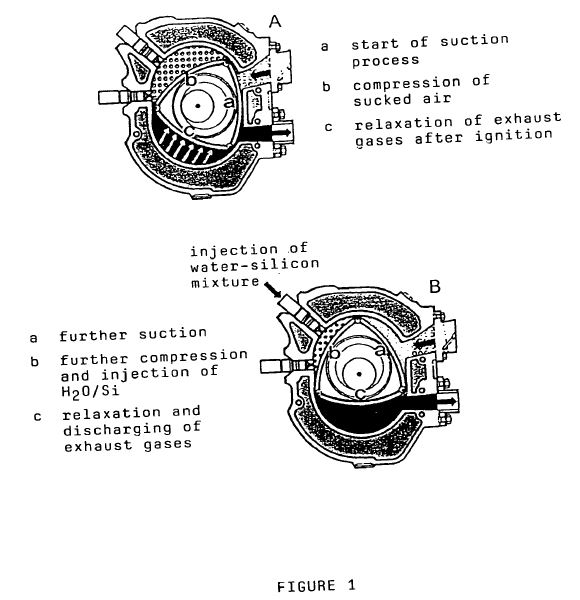
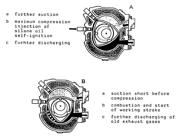
[0001] By German patent 196 12 07 it is known to burn silicon
hydrides with air in a turbine with two combustion chambers.
Dispersed silicon powder or dispersed metal suicides are added
to the fuel in order to completely burn the nitrogen of the
air.
[0002] For example, the stoichiometric combustion equation for
a heptasilane Si7H16 mixed with silicon powder with air
consisting of 20% oxygen and 80% nitrogen is
16H+402->8H2O (equation 1)
7Si+16N2+17 dispersed Si->8Si3N4 (equation 2)
[0003] It is the object of the present invention to describe a
method, as supplement of German patent 196 12 507, for driving
one and the same shaft primarily with an explosion engine and
additionally and secondarily through the mechanical rotary
forces which are generated in a joined turbine chamber in
which the very hot combustion gases from the explosion engine
are mixed with cold air sucked from the atmosphere and are
cooled in this manner. The dusty silicon nitride generated
thereby is captured and subsequently processed for the
generation of ammonia, as known from German patent application
100 48 472.7. A mixture of air and not self-igniting higher
silane has the characteristic to immediately ignite when
compressed. Accordingly, one can desist from an ignition spark
in an explosion engine operated with silane. The difference
with regard to a conventional Diesel engine consists in the
fact that one can desist from the high pressures necessary for
igniting a Diesel air mixture. On the other side, the silane
Diesel fuel cannot be injected during the compression phase
since it ignites with the air untimely. In place of that the
silane oil is only injected at the time of the maximum
compression of the working space volume with high pressure and
ignites instantaneously (see FIGS. 2A, b). Especially,
conventional Wankel engines have the additional disadvantage
that the working space is insufficiently sealed so that a
carbon Diesel operation is practically impossible on account
of the necessary high pressures.
[0004] When operating with silanes the combusiton temperature
within the explosion engine is very high since the nitrogen
does not cool the total reaction as inert passive gas, as this
is the case with conventional combustion reactions, but acts
as an oxidant, i.e. supplies additional combustion heat. Water
H2O and silicon nitride Si3N4 are generated as combustion
products. Therefore, the inner space of the engine has to be
coated with ceramic. However, silicon nitride is used as
material for the construction of turbines and engines just on
account of its hardness and abrasion resistance and heat
resistance up to 1900[deg.] C. If the engine parts adjacent to
the working spaces are coated with silicon nitride the inner
walls of the engine consist of the same substance as the
combustion product Si3N4 which is continuously generated in
the inner space of the engine.
[0005] Since the engine parts are cooled from the outside a
kind of solid-liquid interface layer is formed on the inner
wall of the engine in which the substance silicon nitride is
present in different phases at temperatures up to 1900[deg.]
C. However, since silicon nitride is always present in excess
on account of the continuous new generation a mechanical
abrasion of the engine walls does not occur. Simultaneously,
the interface layer acts as sealant or lubricant.
[0006] Since conventional explosion engines work at
substantially lower temperatures the efficiency of the
described silane explosion engine is substantially higher.
[0007] The amount of the injected silane oil is
stoichiometrically dependent on the amount of the oxygen from
the sucked air since the formation of silicon monoxide is
suppressed. Accordingly, the major part of the 80% nitrogen
portion of the sucked air is not influenced by the reaction
with the silane. In place of that this reacts with
additionally introduced silicon powder (see reaction equations
1 and 2).
[0008] This silicon powder can be either injected as
dispersion together with silane or it is already blown in
during the compression phase together with air or it is used
as dispersion with water (see FIGS. 1B, b). In addition to
that additional water can prevent an overheating of the engine
and simultaneously does additional work by evaporation.
[0009] It has to be taken care that the total amount of
silicon is not larger than the total amount of nitrogen in
every combustion process since otherwise silicon would remain
which might cause abrasion. This is especially important
during a cold start phase. The first two operation steps 1 and
2 of the silane Wankel engine are shown in FIG. 1 while the
operation steps 3 and 4 are shown in FIG. 2 schematicly. The
central triangular rotary piston rotates anticlockwisely
therein. The three sides of the rotary piston are
characterized by the letters a, b and c and form together with
the combustion chamber wall three part-ranges. In these
part-ranges sequentially different processes take place during
the course of rotation of the rotary piston which are shown in
the drawing. After the operation step 4 the combustion cycle
is terminated. The next begins again with operation step 1.
[0010] The combustion products discharged from the explosion
engine have still an enormous temperature. In order to use
this energy in the second part of the engine the hot
combustion gases are mixed with the multiple amount of
compressed cold air. This mixture operates a turbine for the
additional generation of energy whose shaft is connected to
the shaft of the explosion engine.
[0011] Consequently, the silicon nitride cooled in this manner
can be subsequently captured or filtered and does not enter
into the atmosphere but into an replacable container.
[0012] Furthermore, if a Wankel engine is used the coupling of
the shaft improves the running characteristic of the same just
at small speeds.
US2004063052
Novel
concept for generating power via an inorganic nitrogen
cycle, based on sand as the starting material and
producing higher silanes
The invention relates to a novel energy concept that relates
to an artificial silicon-nitrogen cycle and that constitutes
the complement to the natural carbon-oxygen cycle. Pure
silicon is produced from sand using solar energy. By repeated
Muller-Rochow synthesis with silylchlorides the silicon is
converted to higher silanes. The silylchlorides used are
either silicons derived from chemical wastes or are
economically produced from monosilanes or disilanes. They are
mixed with silicon powder and combusted with air to give H2O
and silicon nitride Si3H4, thereby generating power. The
silicon nitride is converted to ammonia NH3 under alkaline
conditions, thereby producing silicates. Part of the NH3 is
converted to follow-on products, the major portion however is
combusted with air to give H2O and N2, thereby generating
power. The N2 cycle is thereby closed.
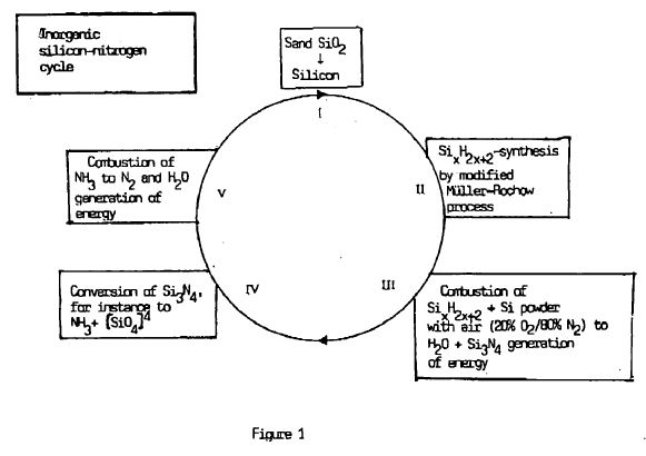
[0001] In the periodic system of elements silicon is situated
directly below carbon and is very similar to it. However, the
hydrogen compounds of the silicon have some differences with
respect to the hydrocarbons. Already Friedrich Wöhler
discovered the silicon homologue of the methan CH4, i.e.
monosilane SiH4, during the change of the century. At the
beginning of the 20th century Prof. Alfred Stock, Karlsruhe
was able to produce the longer-chain homologues of the
hydrocarbons ethane, propane and butane, namely the disilane
Si2H6, trisilane Si3H8 and tetrasilane n-Si4H10 which,
however, are all self-igniting in air.
[0002] 1951 the silane research started in Cologne with Prof.
Franz Fehér. At the beginning of the seventies his assistant
Peter Plichta succeeded in producing the so-called higher
silanes of the pentasilane Si5H12 to the decasilane Si10R22
for the first time which were unknown until this date (German
patent 21 39 155 (1976)). One came to know that-in contrast to
the opinion up to this date higher silanes do not become
instable with increasing chain length but, in contrast, become
more stable so that, for instance, already the heptasilane
(n-Si7H16) is no more
[0003] Copper Oxide in the Direct Process, a Dangerous
Mixture?"). self-ingniting at ambient temperature. Higher
silanes are handle-safe, non-toxid liquids similar to diesel
oil and thus pumpable.
[0004] Silanes can be used as energy producing fuels (German
patent 42 15 835 (1994), U.S. Pat. No. 5,775,096 (1998)).
[0005] In the following the combustion of hydrocarbons is
compared with the combustion of silicon hydrides.
[0006] As one knows, when combusting hydrocarbons not only the
hydrogen portion but also the carbon portion reacts only with
the 20% oxygen portion of the air:
H2+1/202->H2O and C+O2->CO2
[0007] Disadvantages: The nitrogen portion of the air which is
80% remains unused. Furthermore, the breathing poison carbon
dioxide is generated.
[0008] In contrast to carbon, silicon has the characteristic
to form a very stable nitride compound, i.e. the industrially
known silicon(tetra)nitride Si3N4:
3Si+2N2->Si3N4+750 kJ
[0009] The technical production of Si3N4 was carried out up to
now by the reaction of molecular nitrogen with Si powder at
1100-1400[deg.] C. However, tests carried out at Wacker Chemie
AG have shown that even cold (about 200[deg.] C.) nitrogen
reacts with silicon (catalytically) or ignites (Congress
"Silicon for the Chemical Industry V", May 29-Jun. 2, 2000,
Tromso (Norway), speech of Dr. G. Tamme: "Silicon Cyclone Dust
and Copper Oxide in the Direct Process, a Dangerous
Mixture?").
[0010] In an air breathing driving mechanism the following
reactions are possible:
3Si+2N2->Si3N4+750 kJ (I)
H2+1/202->H2O (II)
Si+O2->SiO2 (III)
[0011] Advantages: The nitrogen of the air can be co-utilized
during the combustion of silanes.
[0012] It is the aim of a combustion with silicon hydrides to
combust the hydrogen portion stoichiometrically with oxygen of
the air in a combustion chamber (as with hydrocarbons),
however, to simultaneously let the nitrogen portion of the air
react with silicon. In order to reach the complete combustion
of the added nitrogen of the air one might add dispersed
silicon powder to the silane fuel (German patent 196 12 507
(1997), U.S. Pat. No. 5,996,332 (1999)). The silane/silicon
mixture remains pumpable.
[0013] For instance, if one selects the n-heptasilane
Si7H16(boiling point 226.8[deg.] C., density 0.859
g/cm<3>) the following stoichiometrical combustion of a
normal air mixture consisting of 20% O2 and 80% N2 results:
16H+402->8H2O
7Si+16N2+additional 17 dispersed Si->8Si3N4
[0014] The chemical equations show that indeed the sucked
amount of air can be used as oxidizing agent with a yield of
100%. During this reaction the inert gas nitrogen has the
function of an oxidant. Furthermore, during this reaction no
breathing poison but in addition to water only silicon nitride
is generated which can be even collected or filtered.
[0015] In order to be able to carry out such a combustion in
practice a jet engine was already developed which manipulates
the very hot combustion gases in two combustion chambers
arranged behind one another in such a manner that a shaft can
be driven (German patent 196 12 507 (1997), U.S. Pat. No.
5,996,332 (1999)). This jet engine serves as substitute for
conventional explosion motors. Furthermore, an air breathing
rocket motor (without oxidation tank) is known which is to be
used in supersonic aircrafts and space shuttles (German
patents 44 37 524 (1996) and 44 39 073 (1996)).
[0016] With the German patent applications 100 46 037 of Sep.
18, 2000and of Sep. 29, 2000 it is known to produce higher
silanes by the repeated use of the modified Muller-Rochow
synthesis (i.e. with silylchlorides instead of
methylchlorides) in a cheap manner.
[0017] Accordingly, the presuppositions are present to make
silanes for the central component of the energy supply of the
future.
[0018] It is the object of the present invention to indicate a
novel chemical, inorganic cycle according to which silicon
dioxide, the main component of the earth crust, at first is
converted into pure silicon by means of the sunlight.
Thereafter, higher silanes produced therefrom are combusted
with nitrogen of the air with the production of energy wherein
silicon nitride Si3N4 is generated. This Si3N4 is converted
into ammonia NH3 in an alkaline manner. During this reaction
silicates are generated either which, however, have not to be
introduced into the cycle since SiO2 is available without any
costs. When combusting NH3, again N2 is generated with the
production of energy so that the nitrogen cycle is closed.
[0019] On principle, the individual steps are known, can be
found in chemistry books or are already protected.
[0020] However, the present invention describes the idea to
connect the individual known steps to a cyclic system which is
similar to that of the natural carbon cycle. The conventional
carbon cycle consists of the dualism or the symbiosis of the
organisms of the plants on the one side and of the living
beings on the other. side: CO2 is assimilated in the plants by
photosynthesis with the assistance of sunlight and O2 is
generated. The products of hydrocarbons generated in the
plants during this procedure serve as food for animals and
human beings. The oxygen generated by the plants is breathed
by the animals and human beings wherein energy is produced.
During this procedure CO2 is generated which is needed by the
plants for surviving.
[0021] During the millions of years of the evolution a balance
adjusted which keeps the carbon dioxide portion in the
atmosphere constant. However, this balance has become more and
more unsteady with the beginning of the industrial era up to
now. The more and more increasing industrial CO2 output
threatening the whole ecological system worldwide is
accompanied by the fact that the crude oil reserves become
more and more shorter.
[0022] Furthermore, it is an object of the present invention
to show a way out of this more and more critical situation.
[0023] The advantages of the use of silanes as fuels is the
unlimited availability of the element silicon in contrast to
the very limited crude oil sources. 25% of the earth crust
consist of silicon. For instance, sand has the chemical
formula SiO2.
[0024] (I) The high demand for pure silicon can be met by
reducing the sand (SiO2) with coal and solar current in an
electrical arc furnace in situ to obtain pure silicon. In the
same manner as the sunlight provides in the plants for the use
of electrons for the C-C-coupling, in the here described
inorganic cycle electrical current is generated by means of
solar cells consisting of silicon, the generated electrical
current being required for. the production of pure silicon in
the arc furnace.
[0025] The pure CO2 generated in this process can be used for
the generation of the basic organic chemical substance
methanol so that the CO2 does not enter the atmosphere.
Methanol is an upgraded form of coal. The hydrogen required
for the upgrading of CO2 for methanol CH3OH according to the
formula CO2+3H2 ->CH3OH+H2O is generated by electrolysis
wherein the electrical current necessary herefor is generated
by the solar cells.
[0026] (II) In the next step higher silanes are produced from
the silicon by the modified Müller-Rochow synthesis with
silylchlorides. For this, as silylchlorides ideally industrial
waste of the silicon chemistry, as methyl chlorodisilanes,
which otherwise have to be discarded in an expensive manner,
is to be used. Alternatively, one obtains the silylchlorides
by the chlorination of monosilanes and disilanes generated in
large amounts during the acidic decomposition of magnesium
silicide.
[0027] (III) In the third step the higher silanes are
combusted to water H2O and silicon nitride Si3N4 with the
addition of dispersed silicon powder with atmospheric air (20%
O2, 80% N2). This silicon nitride Si3N4 which is also required
in the industry is a grey-white completely non-toxic dust
which melts only at temperatures of about 1900[deg.] C. with
decomposition.
[0028] (IV) Si3N4 can be solved in lyes and can be converted
into ammonia NH3. The silicates which are generated in this
process are harmless and have not to be recycled since sand
SiO2 is available in large amounts. Parts of the ammonia can
be used for the production of artificial fertilizer.
[0029] (V) However, the major part should be combusted in the
next step with atmospheric air to nitrogen N2 and water H2O
again with a high output of heat. By this, nitrogen is again
introduced into the atmosphere which is then again available
for the combustion of the higher silanes.
[0030] The above-described reactions result in their
cooperation in a novel chemical cycle which is shown in FIG.
1.
[0031] The described silicon-nitrogen cycle represents a
completely novel energy concept. This cycle is the artificial
complement to the natural carbon-oxygen cycle. The silicon era
was announced by the introduction of silicon rectifiers,
transistors, diodes, memory chips etc. in physics and with the
introduction of silicon oils and silicon plastics in
chemistry, with the cycle introduced here it finally succeeds.
It has to be emphasized that the energy set free from the
described cycle, in the last analysis, stems from the
sunlight, as this is the case with the photosynthesis.
[0032] Indeed, the five individual steps of the cycle are not
novel per se. However, the complete cycle is novel in the art.
DE102006041605
Producing silane fuels by high-pressure synthesis...
Producing silane fuels by high-pressure synthesis comprises
producing monosilane from finely divided etched crystalline
silicon at 300[deg] C using a catalyst, contacting the
monosilane with silicon and catalyst at a temperature below
300[deg] C and performing a third step to increase the chain
length of the silanes to produce a fuel with a consistency and
boiling point similar to that of diesel fuel. CHEMICAL
ENGINEERING - Preferred Process: The catalyst is e.g. subgroup
elements or their mixtures with metal oxides. The product
comprises n- and iso-silanes with an average chain length of
about five silicon atoms.
The gaseous silanes: monosilane (SiH4) to 80% and disilane
(Si2H6) to 15%, as well as the liquid silanes trisilan (Si3H8)
and tetrasilane are formed during the decomposition of
magnesium silicide (Mg2Si) in hot acid, which is called
Stocksch's method (Si4H10). Higher liquid silanes were
produced by F. Fehér in 1974, after winning three liters of a
liquid crude silane mixture in 1970. For example, he gained
over 700 grams of n- and iso-pentasilane. Previously, in 1970,
his university assistant, P. Plichta, had succeeded in
obtaining silanes with five, six, seven, eight, nine and ten
silicon atoms as pure pure iso- and iso-isomers in the
milliliter range by simple pyrolysis of tri- and tetrasilane
DE 21 39 155). It was found that higher silanes, in contrast
to the theory (A. Stock), are completely stable at room
temperature. The proven false view of the instability of the
silane is still 36 years later still in the chemist's books in
this world.
While the boranes prepared by Stock were used, which led to
the award of a Nobel Prize, the liquid silanes first came into
contact with DE 44 37 524, because P. Plichta demonstrated
their nitrogen combustion in 1994. In 1970 the monosilane was
still fired at the only silane institute in the world because
nobody had grasped its importance for the production of
photosilicon and computer chip silicon. In the meantime,
monosilane is produced industrially in quantities of thousands
of tons.
The representation of raw silicon in Norway is very expensive.
Accordingly, chlorosilanes and monosilane are so expensive for
the production of photosilicon that the generation of
electricity from light via solar cells does not occur to the
extent that electricity can be produced on the roofs of
buildings all over the world. With the patent applications AZ
10 2006 023 515.0 and AZ 10 2006 029 282.0, P. Plichta was
able to prove that oil-containing sands / shales can be very
cheap photosilicon. As early as the year 2000, P. Plichta had
filed a major synthesis of higher silanes by means of a
modified Müller-Rochow process (AZ 100 59 625.8). In 2006, P.
Plichta developed a "silane fuel cell with pure nitrogen
silicon combustion from fed-in air." According to P. Plichta
in 2006, a "vehicle engine with silane nitrogen drive for the
generation of three-phase current for driving a motor vehicle
without mobile engine parts" (AZ 10 2006 009 907.9) "(AZ 10
2006 028 063.6).2003
P. Plichta and A. Kornath (University of Dortmund) succeeded
in developing a large-scale synthesis of pure cyclopentasilane
by means of an organic base diphenyl dichlorosilane
(Phe2CL2Si) for the first time. In the meantime, Plichta's
assistant, B. Hidding, 2003 (University of the German Armed
Forces, Munich), had proved that all combustion spirals
published by F. Fehér were wrong. Plichta, Hidding, and
Kornath also demonstrated that the combustion tyne of
cyclopentasilan, which was measured by N. Auner 1998
(Unversität Frankfurt) at the ICT Berghausen, is completely
false.
Since liquid silanes will be the fuel of the future, it is
necessary to develop a process to present liquid silanes so
cheaply that they will completely replace the fuels gasoline,
diesel and liquid hydrogen. At the instigation of P. Plichta
at the University of Dortmund 2003 preliminary experiments
were undertaken.
The object of the present invention is to develop a process
for producing gaseous and liquid silanes from inexpensive
crystalline silicon. The process is characterized by
synthesizing monosilane as a whole in two steps in order to
convert it into liquid silanes. These liquid silanes could
then be pyrolyzed if it is necessary not to produce
self-ignitable silanes.
Preliminary tests have shown that etched silicon reacts with
monosilane (SiH4) with the addition of a catalyst in an
autoclave. The choice of the catalyst such as platinum or
copper is apparently not important. More importantly, it is
very difficult to grind crystalline photosilicon obtained from
oil sands / oil shales and to treat them with hydrogen under
pressure at temperatures of over 300 °. The SiH4 / H2 mixture
obtained in this way can then immediately be converted into a
second autoclave, the main being trisilane (Si3H8). The gas
mixture of hydrogen, monosilane, disilane, trisilane and
tetrasilane can then be converted into a third autoclave at
temperatures of about 250 ° C. and react again with
crystalline silicon. The higher silane mixtures obtained in
this way can be fractionated in vacuo. Similar to gasoline or
diesel, this fuel is also a mixture of n- and iso-silanes with
a high proportion of pentasilane.
Since crystalline silicon is obtained directly from the
production of oil sand / oil shale because silicon fluoride
(SiF4) is liberated (AZ 59607219.8 P. Plichta) and is
converted into aluminum fluoride by means of aluminum grits in
a termite process, the production of cheap synthetic
silicon-containing gasolines is nothing More in the way. The
dangers of the oil shortage are now done.
DE102006009907
Production
of a rotary stream for driving a motor vehicle comprises
using a silane-air drive which burns atomic hydrogen of
the silane chain into water and free silicon radicals are
burned with atmospheric nitrogen to form silicon nitride
Production of a rotary stream comprises using a silane-air
drive which burns atomic hydrogen of the silane chain into
water and the free silicon radicals are burned with
atmospheric nitrogen to form silicon nitride. The residual
nitrogen is likewise burned using excess liquid or gaseous
silane. Preferred Features: Blades of the gas turbine of the
motor are coated with silicon nitride so that the silicon
nitride particles are not attacked at a temperature of less
than 300[deg] C.
By patent application, it is known that liquid silanes (a
mixture of Si3H8 to Si8H18) can be burned to the point that no
silicon oxides are formed, but only water vapor, amorphous
silicon nitride and the main atomic hydrogen. (Plichta)
According to Gibbs-Helmholtz equation: F = ?H + ?S, a molecule
Si3N4 is formed during the union of three Si atoms with four N
atoms, which is important for entropy. Si3N4 (Wöhler 1859) is
indeed a solid noble gas.
The patent has already been attempted in a two-chamber motor
without mechanical elements to drive a shaft with two turbine
elements in such a way that heat is converted into rotational
energy by silane combustion, the heat being cooled down by
compressed cold air and gas pressure being generated.
The present invention is based on the object of constructing a
motor vehicle motor which no longer has mechanical motor
elements, such as pistons or washers, and thus does not have
to be lubricated, characterized in that two stoichiometric
equations are used in the invention which prove that the
method Thermodynamically not only true, but also technically
feasible.
The method is now to be explained in detail with reference to
the appendix: 1. The system shows an air intake funnel (1). 2.
Behind it is a compression turbine, which is driven
electrically (2), (+ -). 3. Compressed air is conducted into a
combustion chamber through the air channel (1), (2) (FIG. 4).
4. Liquid silane or compressed gaseous silane is injected into
the same combustion chamber (11), (12). 5. The combustion
chambers (4), (6), (7) are of silicon ceramics such as silicon
nitride or silicon carbide. According to the state of the art,
an SiC chamber can be produced three-dimensionally by a
machine in such a way that it contains a network of cooling
channels. (These are not explicitly shown in the drawing. ) 6.
Silanes are oxidized by heat during the heat so that the air
oxygen and the air nitrogen are stoichiometrically combusted,
which is to be represented by means of a hexasilane: 2Si6H14 +
7O2 + 8N2? 4Si3N4 + 14H2O + ?W The amount of nitrogen unburned
per unit time is calculated according to the equation
41/2Si6H14 + 18N2? 9Si3N4 + 63H1 +? W is oxidized and a large
amount of atomic hydrogen is released.
7. Since the motor housing (4) is extremely loaded despite
cooling at the occurring temperatures of about 3000 °, it is
absolutely necessary to inject a calculated amount of water
(3) at a particular time. Here, the water evaporates and
generates pressure, while the pressure drops due to the
disappearance of the nitrogen. Overall, heat of 3,000 ° is
converted into gas pressure of about 1000 °. 8. The highly
compressed water vapor / silicon nitride oil mist (14H2O +
13Si3N4) and the atomic hydrogen (63H1) are chased through a
Lavalle nozzle (6). The atomic hydrogen has a lifetime of half
a second so that it reaches the chamber 7 as the H atom. 9.
Behind the Lavalle nozzle the pressure continues to rise in
the funnel-shaped space (7). 10. In order to burn the atomic
hydrogen with oxygen, cold compressed air is supplied to each
time unit via supply lines (5). This creates further heat and
water vapor. It is necessary to come down from the high
temperature to about 300 ° by further feeding compressed air.
All in all, heat is simply converted into work and the large
turbine (8) is driven. 11. Behind the large gas turbine (8),
which generates alternating current for the drive of the motor
vehicle and the compressed air pumps, the now 300 ° hot
mixture of water vapor, air and silicon nitride powder is to
be filtered (9). The dust filter acts like a silencer. The
silicon nitride is collected in the dust filter (9), the
filter wall being applied to a screen jacket. 12.200 ° hot
water vapor and air escape (10). 13. The gas turbine (8) is
connected to a three-phase alternator (13). The electric
current (+ -) is transmitted to the electric motors driving
the wheels of the motor vehicle (Patent No. 14). 1. The system
shows an air intake funnel (1). 2. Behind it is a compression
turbine, which is driven electrically (2), (+ -). 3.
Compressed air is conducted into a combustion chamber through
the air channel (1), (2) (FIG. 4).
4. Liquid silane or compressed gaseous silane is injected into
the same combustion chamber (11), (12). 5. The combustion
chambers (4), (6), (7) are of silicon ceramics such as silicon
nitride or silicon carbide. According to the state of the art,
an SiC chamber can be produced three-dimensionally by a
machine in such a way that it contains a network of cooling
channels. (These are not explicitly shown in the drawing. ) 6.
Silanes are oxidized by heat during the heat so that the air
oxygen and the air nitrogen are stoichiometrically combusted,
which is to be represented by a hexasilane: 2Si6H14 + 7O2 +
8N2? 4Si3N4 + 14H2O + ?W The amount of nitrogen unburned per
unit time is calculated according to the equation 41/2Si6H14 +
18N2? 9Si3N4 + 63H1 +? W is oxidized and a large amount of
atomic hydrogen is released. 7. Since the motor housing (4) is
extremely loaded despite cooling at the occurring temperatures
of approx. 3,000 °, it is absolutely necessary to inject a
calculated amount of water (3) at a particular time.
Here, the water evaporates and generates pressure, while the
pressure drops due to the disappearance of the nitrogen.
Overall, heat of 3,000 ° is converted into gas pressure of
about 1000 °. 8. The highly compressed water vapor / silicon
nitride oil mist (14H2O + 13Si3N4) and the atomic hydrogen
(63H1) are chased through a Lavalle nozzle (6). The atomic
hydrogen has a lifetime of half a second so that it reaches
the chamber 7 as the H atom. 9. Behind the Lavalle nozzle the
pressure continues to rise in the funnel-shaped space (7). 10.
In order to burn the atomic hydrogen with oxygen, cold
compressed air is supplied to each time unit via supply lines
(5). This creates further heat and water vapor. It is
necessary to come down from the high temperature to about 300
° by further feeding compressed air. All in all, heat is
simply converted into work and the large turbine (8) is
driven. 11. Behind the large gas turbine (8), which generates
alternating current for the drive of the motor vehicle and the
compressed air pumps, the now 300 ° hot mixture of water
vapor, air and silicon nitride powder is to be filtered (9).
The dust filter acts like a silencer. The silicon nitride is
collected in the dust filter (9), the filter wall being
applied to a screen jacket. 12.200 ° hot water vapor and air
escape (10). 13. The gas turbine (8) is connected to a
three-phase alternator (13). The electric current (+ -) is
transmitted to the electric motors driving the wheels of the
motor vehicle (Patent No. 14). 1. The system shows an air
intake funnel (1). 2. Behind it is a compression turbine,
which is driven electrically (2), (+ -). 3. Compressed air is
conducted into a combustion chamber through the air channel
(1), (2) (FIG. 4). 4. Liquid silane or compressed gaseous
silane is injected into the same combustion chamber (11),
(12). 5. The combustion chambers (4), (6), (7) are of silicon
ceramics such as silicon nitride or silicon carbide. According
to the state of the art, an SiC chamber can be produced
three-dimensionally by a machine in such a way that it
contains a network of cooling channels.
(These are not explicitly shown in the drawing. ) 6. Silanes
are oxidized by heat during the heat so that the air oxygen
and the air nitrogen are stoichiometrically combusted, which
is to be represented by a hexasilane: 2Si6H14 + 7O2 + 8N2?
4Si3N4 + 14H2O + ?W The amount of nitrogen unburned per unit
time is calculated according to the equation 41/2Si6H14 +
18N2? 9Si3N4 + 63H1 +? W is oxidized and a large amount of
atomic hydrogen is released. 7. Since the motor housing (4) is
extremely loaded despite cooling at the occurring temperatures
of about 3000 °, it is absolutely necessary to inject a
calculated amount of water (3) at a particular time. Here, the
water evaporates and generates pressure, while the pressure
drops due to the disappearance of the nitrogen. Overall, heat
of 3,000 ° is converted into gas pressure of about 1000 °. 8.
The highly compressed water vapor / silicon nitride oil mist
(14H2O + 13Si3N4) and the atomic hydrogen (63H1) are chased
through a Lavalle nozzle (6).
The atomic hydrogen has a lifetime of half a second so that it
reaches the chamber 7 as the H atom. 9. Behind the Lavalle
nozzle the pressure continues to rise in the funnel-shaped
space (7). 10. In order to burn the atomic hydrogen with
oxygen, cold compressed air is supplied to each time unit via
supply lines (5). This creates further heat and water vapor.
It is necessary to come down from the high temperature to
about 300 ° by further feeding compressed air. All in all,
heat is simply converted into work and the large turbine (8)
is driven. 11. Behind the large gas turbine (8), which
generates alternating current for the drive of the motor
vehicle and the compressed air pumps, the now 300 ° hot
mixture of water vapor, air and silicon nitride powder is to
be filtered (9). The dust filter acts like a silencer. The
silicon nitride is collected in the dust filter (9), the
filter wall being applied to a screen jacket.
12.200 ° hot water vapor and air escape (10). 13. The gas
turbine (8) is connected to a three-phase alternator (13). The
electric current (+ -) is transmitted to the electric motors
driving the wheels of the motor vehicle (Patent No. 14). 1.
The system shows an air intake funnel (1). 2. Behind it is a
compression turbine, which is driven electrically (2), (+ -).
3. Compressed air is conducted into a combustion chamber
through the air channel (1), (2) (FIG. 4). 4. Liquid silane or
compressed gaseous silane is injected into the same combustion
chamber (11), (12). 5. The combustion chambers (4), (6), (7)
are of silicon ceramics such as silicon nitride or silicon
carbide. According to the state of the art, an SiC chamber can
be produced three-dimensionally by a machine in such a way
that it contains a network of cooling channels. (These are not
explicitly shown in the drawing. ) 6. Silanes are oxidized by
heat during the heat so that the air oxygen and the air
nitrogen are stoichiometrically combusted, which is to be
represented by a hexasilane: 2Si6H14 + 7O2 + 8N2? 4Si3N4 +
14H2O + ?W The amount of nitrogen unburned per unit time is
calculated according to the equation 41/2Si6H14 + 18N2? 9Si3N4
+ 63H1 +? W is oxidized and a large amount of atomic hydrogen
is released.
7. Since the motor housing (4) is extremely loaded despite
cooling at the occurring temperatures of about 3000 °, it is
absolutely necessary to inject a calculated amount of water
(3) at a particular time. Here, the water evaporates and
generates pressure, while the pressure drops due to the
disappearance of the nitrogen. Overall, heat of 3,000 ° is
converted into gas pressure of about 1000 °. 8. The highly
compressed water vapor / silicon nitride oil mist (14H2O +
13Si3N4) and the atomic hydrogen (63H1) are chased through a
Lavalle nozzle (6). The atomic hydrogen has a lifetime of half
a second so that it reaches the chamber 7 as the H atom. 9.
Behind the Lavalle nozzle the pressure continues to rise in
the funnel-shaped space (7). 10. In order to burn the atomic
hydrogen with oxygen, cold compressed air is supplied to each
time unit via supply lines (5). This creates further heat and
water vapor. It is necessary to come down from the high
temperature to about 300 ° by further feeding compressed air.
All in all, heat is simply converted into work and the large
turbine (8) is driven. 11. Behind the large gas turbine (8),
which generates alternating current for the drive of the motor
vehicle and the compressed air pumps, the now 300 ° hot
mixture of water vapor, air and silicon nitride powder is to
be filtered (9). The dust filter acts like a silencer. The
silicon nitride is collected in the dust filter (9), the
filter wall being applied to a screen jacket. 12.200 ° hot
water vapor and air escape (10). 13. The gas turbine (8) is
connected to a three-phase alternator (13). The electric
current (+ -) is transmitted to the electric motors driving
the wheels of the motor vehicle (Patent No. 14). 1. The system
shows an air intake funnel (1). 2. Behind it is a compression
turbine, which is driven electrically (2), (+ -). 3.
Compressed air is conducted into a combustion chamber through
the air channel (1), (2) (FIG. 4)
4. Liquid silane or compressed gaseous silane is injected into
the same combustion chamber (11), (12). 5. The combustion
chambers (4), (6), (7) are of silicon ceramics such as silicon
nitride or silicon carbide. According to the state of the art,
an SiC chamber can be produced three-dimensionally by a
machine in such a way that it contains a network of cooling
channels. (These are not explicitly shown in the drawing. ) 6.
Silanes are oxidized by heat during the heat so that the air
oxygen and the air nitrogen are stoichiometrically combusted,
which is to be represented by a hexasilane: 2Si6H14 + 7O2 +
8N2? 4Si3N4 + 14H2O + ?W The amount of nitrogen unburned per
unit time is calculated according to the equation 41/2Si6H14 +
18N2? 9Si3N4 + 63H1 +? W is oxidized and a large amount of
atomic hydrogen is released. 7. Since the motor housing (4) is
extremely loaded despite cooling at the occurring temperatures
of about 3000 °, it is absolutely necessary to inject a
calculated amount of water (3) at a particular time.
Here, the water evaporates and generates pressure, while the
pressure drops due to the disappearance of the nitrogen.
Overall, heat of 3,000 ° is converted into gas pressure of
about 1000 °. 8. The highly compressed water vapor / silicon
nitride oil mist (14H2O + 13Si3N4) and the atomic hydrogen
(63H1) are chased through a Lavalle nozzle (6). The atomic
hydrogen has a lifetime of half a second so that it reaches
the chamber 7 as the H atom. 9. Behind the Lavalle nozzle the
pressure continues to rise in the funnel-shaped space (7). 10.
In order to burn the atomic hydrogen with oxygen, cold
compressed air is supplied to each time unit via supply lines
(5). This creates further heat and water vapor. It is
necessary to come down from the high temperature to about 300
° by further feeding compressed air. All in all, heat is
simply converted into work and the large turbine (8) is
driven. 11. Behind the large gas turbine (8), which generates
alternating current for the drive of the motor vehicle and the
compressed air pumps, the now 300 ° hot mixture of water
vapor, air and silicon nitride powder is to be filtered (9).
The dust filter acts like a silencer. The silicon nitride is
collected in the dust filter (9), the filter wall being
applied to a screen jacket. 12.200 ° hot water vapor and air
escape (10). 13. The gas turbine (8) is connected to a
three-phase alternator (13). The electric current (+ -) is
transmitted to the electric motors driving the wheels of the
motor vehicle (Patent No. 14). 1. The system shows an air
intake funnel (1). 2. Behind it is a compression turbine,
which is driven electrically (2), (+ -). 3. Compressed air is
conducted into a combustion chamber through the air channel
(1), (2) (FIG. 4). 4. Liquid silane or compressed gaseous
silane is injected into the same combustion chamber (11),
(12). 5. The combustion chambers (4), (6), (7) are of silicon
ceramics such as silicon nitride or silicon carbide. According
to the state of the art, an SiC chamber can be produced
three-dimensionally by a machine in such a way that it
contains a network of cooling channels.
(These are not explicitly shown in the drawing. ) 6. Silanes
are oxidized by heat during the heat so that the air oxygen
and the air nitrogen are stoichiometrically combusted, which
is to be represented by a hexasilane: 2Si6H14 + 7O2 + 8N2?
4Si3N4 + 14H2O + ?W The amount of nitrogen unburned per unit
time is calculated according to the equation 41/2Si6H14 +
18N2? 9Si3N4 + 63H1 +? W is oxidized and a large amount of
atomic hydrogen is released. 7. Since the motor housing (4) is
extremely loaded despite cooling at the occurring temperatures
of about 3000 °, it is absolutely necessary to inject a
calculated amount of water (3) at a particular time. Here, the
water evaporates and generates pressure, while the pressure
drops due to the disappearance of the nitrogen. Overall, heat
of 3,000 ° is converted into gas pressure of about 1000 °. 8.
The highly compressed water vapor / silicon nitride oil mist
(14H2O + 13Si3N4) and the atomic hydrogen (63H1) are chased
through a Lavalle nozzle (6).
The atomic hydrogen has a lifetime of half a second so that it
reaches the chamber 7 as the H atom. 9. Behind the Lavalle
nozzle the pressure continues to rise in the funnel-shaped
space (7). 10. In order to burn the atomic hydrogen with
oxygen, cold compressed air is supplied to each time unit via
supply lines (5). This creates further heat and water vapor.
It is necessary to come down from the high temperature to
about 300 ° by further feeding compressed air. All in all,
heat is simply converted into work and the large turbine (8)
is driven. 11. Behind the large gas turbine (8), which
generates alternating current for the drive of the motor
vehicle and the compressed air pumps, the now 300 ° hot
mixture of water vapor, air and silicon nitride powder is to
be filtered (9). The dust filter acts like a silencer. The
silicon nitride is collected in the dust filter (9), the
filter wall being applied to a screen jacket.
12.200 ° hot water vapor and air escape (10). 13. The gas
turbine (8) is connected to a three-phase alternator (13). The
electric current (+ -) is transmitted to the electric motors
driving the wheels of the motor vehicle (Patent No. 14). 1.
The system shows an air intake funnel (1). 2. Behind it is a
compression turbine, which is driven electrically (2), (+ -).
3. Compressed air is conducted into a combustion chamber
through the air channel (1), (2) (FIG. 4). 4. Liquid silane or
compressed gaseous silane is injected into the same combustion
chamber (11), (12). 5. The combustion chambers (4), (6), (7)
are of silicon ceramics such as silicon nitride or silicon
carbide. According to the state of the art, an SiC chamber can
be produced three-dimensionally by a machine in such a way
that it contains a network of cooling channels. (These are not
explicitly shown in the drawing. ) 6. Silanes are oxidized by
heat during the heat so that the air oxygen and the air
nitrogen are stoichiometrically combusted, which is to be
represented by a hexasilane: 2Si6H14 + 7O2 + 8N2? 4Si3N4 +
14H2O + ?W The amount of nitrogen unburned per unit time is
calculated according to the equation 41/2Si6H14 + 18N2? 9Si3N4
+ 63H1 +? W is oxidized and a large amount of atomic hydrogen
is released.
7. Since the motor housing (4) is extremely loaded despite
cooling at the occurring temperatures of about 3000 °, it is
absolutely necessary to inject a calculated amount of water
(3) at a particular time. Here, the water evaporates and
generates pressure, while the pressure drops due to the
disappearance of the nitrogen. Overall, heat of 3,000 ° is
converted into gas pressure of about 1000 °. 8. The highly
compressed water vapor / silicon nitride oil mist (14H2O +
13Si3N4) and the atomic hydrogen (63H1) are chased through a
Lavalle nozzle (6). The atomic hydrogen has a lifetime of half
a second so that it reaches the chamber 7 as the H atom. 9.
Behind the Lavalle nozzle the pressure continues to rise in
the funnel-shaped space (7). 10. In order to burn the atomic
hydrogen with oxygen, cold compressed air is supplied to each
time unit via supply lines (5). This creates further heat and
water vapor. It is necessary to come down from the high
temperature to about 300 ° by further feeding compressed air.
All in all, heat is simply converted into work and the large
turbine (8) is driven. 11. Behind the large gas turbine (8),
which generates alternating current for the drive of the motor
vehicle and the compressed air pumps, the now 300 ° hot
mixture of water vapor, air and silicon nitride powder is to
be filtered (9). The dust filter acts like a silencer. The
silicon nitride is collected in the dust filter (9), the
filter wall being applied to a screen jacket. 12.200 ° hot
water vapor and air escape (10). 13. The gas turbine (8) is
connected to a three-phase alternator (13). The electric
current (+ -) is transmitted to the electric motors driving
the wheels of the motor vehicle (Patent No. 14). 1. The system
shows an air intake funnel (1). 2. Behind it is a compression
turbine, which is driven electrically (2), (+ -). 3.
Compressed air is conducted into a combustion chamber through
the air channel (1), (2) (FIG. 4).
4. Liquid silane or compressed gaseous silane is injected into
the same combustion chamber (11), (12). 5. The combustion
chambers (4), (6), (7) are of silicon ceramics such as silicon
nitride or silicon carbide. According to the state of the art,
an SiC chamber can be produced three-dimensionally by a
machine in such a way that it contains a network of cooling
channels. (These are not explicitly shown in the drawing. ) 6.
Silanes are oxidized by heat during the heat so that the air
oxygen and the air nitrogen are stoichiometrically combusted,
which is to be represented by a hexasilane: 2Si6H14 + 7O2 +
8N2? 4Si3N4 + 14H2O + ?W The amount of nitrogen unburned per
unit time is calculated according to the equation 41/2Si6H14 +
18N2? 9Si3N4 + 63H1 +? W is oxidized and a large amount of
atomic hydrogen is released. 7. Since the motor housing (4) is
extremely loaded despite cooling at the occurring temperatures
of about 3000 °, it is absolutely necessary to inject a
calculated amount of water (3) at a particular time.
Here, the water evaporates and generates pressure, while the
pressure drops due to the disappearance of the nitrogen.
Overall, heat of 3,000° is converted into gas pressure of
about 1000 °. 8. The highly compressed water vapor / silicon
nitride oil mist (14H2O + 13Si3N4) and the atomic hydrogen
(63H1) are chased through a Lavalle nozzle (6). The atomic
hydrogen has a lifetime of half a second so that it reaches
the chamber 7 as the H atom. 9. Behind the Lavalle nozzle the
pressure continues to rise in the funnel-shaped space (7). 10.
In order to burn the atomic hydrogen with oxygen, cold
compressed air is supplied to each time unit via supply lines
(5). This creates further heat and water vapor. It is
necessary to come down from the high temperature to about 300
° by further feeding compressed air. All in all, heat is
simply converted into work and the large turbine (8) is
driven. 11. Behind the large gas turbine (8), which generates
alternating current for the drive of the motor vehicle and the
compressed air pumps, the now 300 ° hot mixture of water
vapor, air and silicon nitride powder is to be filtered (9).
The dust filter acts like a silencer. The silicon nitride is
collected in the dust filter (9), the filter wall being
applied to a screen jacket. 12.200° hot water vapor and air
escape (10). 13. The gas turbine (8) is connected to a
three-phase alternator (13). The electric current (+ -) is
transmitted to the electric motors driving the wheels of the
motor vehicle (Patent No. 14). 1. The system shows an air
intake funnel (1). 2. Behind it is a compression turbine,
which is driven electrically (2), (+ -). 3. Compressed air is
conducted into a combustion chamber through the air channel
(1), (2) (FIG. 4). 4. Liquid silane or compressed gaseous
silane is injected into the same combustion chamber (11),
(12). 5. The combustion chambers (4), (6), (7) are of silicon
ceramics such as silicon nitride or silicon carbide. According
to the state of the art, an SiC chamber can be produced
three-dimensionally by a machine in such a way that it
contains a network of cooling channels.
(These are not explicitly shown in the drawing. ) 6. Silanes
are oxidized by heat during the heat so that the air oxygen
and the air nitrogen are stoichiometrically combusted, which
is to be represented by a hexasilane: 2Si6H14 + 7O2 + 8N2?
4Si3N4 + 14H2O + ?W The amount of nitrogen unburned per unit
time is calculated according to the equation 41/2Si6H14 +
18N2? 9Si3N4 + 63H1 +? W is oxidized and a large amount of
atomic hydrogen is released. 7. Since the motor housing (4) is
extremely loaded despite cooling at the occurring temperatures
of about 3000 °, it is absolutely necessary to inject a
calculated amount of water (3) at a particular time. Here, the
water evaporates and generates pressure, while the pressure
drops due to the disappearance of the nitrogen. Overall, heat
of 3,000 ° is converted into gas pressure of about 1000 °. 8.
The highly compressed water vapor / silicon nitride oil mist
(14H2O + 13Si3N4) and the atomic hydrogen (63H1) are chased
through a Lavalle nozzle (6).
The atomic hydrogen has a lifetime of half a second so that it
reaches the chamber 7 as the H atom. 9. Behind the Lavalle
nozzle the pressure continues to rise in the funnel-shaped
space (7). 10. In order to burn the atomic hydrogen with
oxygen, cold compressed air is supplied to each time unit via
supply lines (5). This creates further heat and water vapor.
It is necessary to come down from the high temperature to
about 300 ° by further feeding compressed air. All in all,
heat is simply converted into work and the large turbine (8)
is driven. 11. Behind the large gas turbine (8), which
generates alternating current for the drive of the motor
vehicle and the compressed air pumps, the now 300 ° hot
mixture of water vapor, air and silicon nitride powder is to
be filtered (9). The dust filter acts like a silencer. The
silicon nitride is collected in the dust filter (9), the
filter wall being applied to a screen jacket.
12.200 ° hot water vapor and air escape (10). 13. The gas
turbine (8) is connected to a three-phase alternator (13). The
electric current (+ -) is transmitted to the electric motors
driving the wheels of the motor vehicle (Patent No. 14). 1.
The system shows an air intake funnel (1). 2. Behind it is a
compression turbine, which is driven electrically (2), (+ -).
3. Compressed air is conducted into a combustion chamber
through the air channel (1), (2) (FIG. 4). 4. Liquid silane or
compressed gaseous silane is injected into the same combustion
chamber (11), (12). 5. The combustion chambers (4), (6), (7)
are of silicon ceramics such as silicon nitride or silicon
carbide. According to the state of the art, an SiC chamber can
be produced three-dimensionally by a machine in such a way
that it contains a network of cooling channels. (These are not
explicitly shown in the drawing. ) 6. Silanes are oxidized by
heat during the heat so that the air oxygen and the air
nitrogen are stoichiometrically combusted, which is to be
represented by a hexasilane: 2Si6H14 + 7O2 + 8N2? 4Si3N4 +
14H2O + ?W The amount of nitrogen unburned per unit time is
calculated according to the equation 41/2Si6H14 + 18N2? 9Si3N4
+ 63H1 +? W is oxidized and a large amount of atomic hydrogen
is released.
7. Since the motor housing (4) is extremely loaded despite
cooling at the occurring temperatures of about 3000 °, it is
absolutely necessary to inject a calculated amount of water
(3) at a particular time. Here, the water evaporates and
generates pressure, while the pressure drops due to the
disappearance of the nitrogen. Overall, heat of 3,000 ° is
converted into gas pressure of about 1000 °. 8. The highly
compressed water vapor / silicon nitride oil mist (14H2O +
13Si3N4) and the atomic hydrogen (63H1) are chased through a
Lavalle nozzle (6). The atomic hydrogen has a lifetime of half
a second so that it reaches the chamber 7 as the H atom. 9.
Behind the Lavalle nozzle the pressure continues to rise in
the funnel-shaped space (7). 10. In order to burn the atomic
hydrogen with oxygen, cold compressed air is supplied to each
time unit via supply lines (5). This creates further heat and
water vapor. It is necessary to come down from the high
temperature to about 300 ° by further feeding compressed air.
All in all, heat is simply converted into work and the large
turbine (8) is driven. 11. Behind the large gas turbine (8),
which generates alternating current for the drive of the motor
vehicle and the compressed air pumps, the now 300 ° hot
mixture of water vapor, air and silicon nitride powder is to
be filtered (9). The dust filter acts like a silencer. The
silicon nitride is collected in the dust filter (9), the
filter wall being applied to a screen jacket. 12.200 ° hot
water vapor and air escape (10). 13. The gas turbine (8) is
connected to a three-phase alternator (13). The electric
current (+ -) is transmitted to the electric motors driving
the wheels of the motor vehicle (Patent No. 14).
While a steam-powered locomotive has an efficiency of about
10% and a high-tech TDI motor vehicle has an efficiency of
45%, the present silane nitrogen drive achieves an efficiency
of more than 90% in the illustrated form. Precisely because
silanes disintegrate in the heat and thereby heat is released
and atomic hydrogen, the foundations of thermodynamics have to
be recalculated. The resulting dusty Si 3 N 4 is collected in
a filter bag and fed into the chemical industry and processed
into ammonia by the prior art.
DE102006050193
Recovery of crystalline silicon from liquid silane in
fuel cells or engines...
A method for the recovery of crystalline silicon from liquid
silanes used for hydrogen storage in fuel cells or engines
with no moving parts, in which the silicon radicals left after
the removal of atomic hydrogen are cooled to form crystalline
silicon which can be recycled to the silane production
process, while the atomic hydrogen rapidly combines to form
molecular hydrogen for use in the fuel cell. A method for the
recovery of crystalline silicon (I) from liquid silanes used
for storing hydrogen in fuel cells or engines with no moving
parts, in which the silicon radicals left after the removal of
atomic hydrogen form (I) on cooling, so that the silicon
obtained can be recycled to the silane production process;
this offers a new approach to silicon production which should
be changed due to the cost of carbon and electricity, while
the silicon formed can be used again (crystalline (I) has
until now been obtained by the pyrolysis of chlorosilanes). In
this way silicon can perform the functions required of a metal
hydride storage medium and the hydrogen from the silanes can,
e.g. keep a fuel cell running so that the rest of the silicon
acts as an accumulator which admittedly stores no electrons
but stores atomic hydrogen which has a half-life of 0.5 second
before it combines to form molecular hydrogen. Skilful
arrangement should enable the effective operation of a fuel
cell and replace the prior-art chemical process (pyrolysis of
silicon radicals with nitrogen) because, whereas in a scramjet
atomic hydrogen has to leave the jet nozzle unburnt due to its
low molecular weight, in a car the fuel cell supplies useful
current directly, while the silicon atoms crystallise out on
cooling and do not migrate into the fuel cell.
With patent application AZ 10 2006 041 605.8 "Pressure
synthesis of higher silanes" (P. Plichta) and with AZ 10 2006
028 063.6 "Silane fuel cell with pure nitrogen / silicon
combustion from fed air" (P. Plichta) and AZ 10 2006 009 907.9
" (P. Plichta), it is known that liquid silanes are
excellently suitable as hydrogen storage media because the
silane chain decomposes in atomic hydrogen and in silicon
radicals on heating. See: (AZ 10 2006 038 912.3) "Method for
operating a single-stage blasting machine in the sub-, over-
and hypersonic range: scramjet, which stoichiometrically burns
liquid silanes with the 78% nitrogen content of the fed air,
the hot, unburned Atomic hydrogen of the silane chain with its
Mg of 1 represents the main thrust element. (Plichta, P.)
The present invention is based on the object of using atomic /
molecular hydrogen H1 / H2 as energy storage means with the
aid of silicon / silanes using a cyclic method. That the
recovery of the pyrolytically separated atomic / crystalline
silicon is used worldwide. Thus, it becomes possible to
drastically reduce the production cost of the fuel silane. In
simple terms, liquid silanes represent an accumulator that
does not store electrons but hydrogen. For decades, we have
been looking for a metal hydride store.
In the catalytic representation, for example, of pentasilane
(AZ 10 2006 041 605.8) by pressing monosilane onto the etched
silicon, neo-pentasilane Si (Si H 3) 4 would have to be
formed. A simple consideration shows that such an isomeric
silane has a much lower boiling point than the n-pentasilane
and the iso-pentasilane (DE 21 39 155) "Process for the
preparation of higher silanes and germanenes" (P. Plichta).
The cruciform compound neo-pentasilane decomposes to four
silicon radicals at about 300 ° C. during the heat and
provides heat upon decomposition (AZ 10 2006 038 912.3) (P.
Plichta). The remaining twelve atomic hydrogen atoms have a
half-life of half a second before they turn into molecular
hydrogen H2 with the release of heat. This hydrogen can now be
used to drive a fuel cell or a motor without mechanical
elements. The remaining silicon radicals can be converted back
into crystalline silicon by cooling, so that this silicon can
be returned to the production process of silanes by
collecting.
In this way it is achieved that silicon in the form of silanes
can be used as hydrogen storage, since subsequently no
expensive crude silicon or even more expensive pure
crystalline silicon is required permanently for the production
process of higher silanes. Silane is traditionally represented
with the aid of acid decomposition in such a way that hydrogen
in statu nascendi forms gaseous silanes at the silicon anions
in the main. During the combustion of silanes, these atomic
hydrogen atoms are released again, so that the cleavage yields
energy which has not been disclosed by inorganic textbooks.
(Plichta, P. & B. Hidding)
The production of raw silicon costs coal and electricity,
because the 2,200 ° C heat can only be generated by expensive
electric power. The subsequent chlorination for the production
of crystalline silicon was modified by P. Plichta by
fluorination. (AZ 10 2006 023 515.0 and AZ 10 2006 029 282.0)
because the oil sands and oil shale used are available as
practically free resources. Overall, a very large amount of
higher silanes, For example, neo-pentasilane, in order to
reduce the production of such silanes by repeatedly using the
same amount of liberated crystalline silicon.
The described hydrogen storage silicon is thus produced
without the use of coal and electrically produced heat and
then processed with the hydrogen from oil sand / shale to
silanes.
Since liquid hydrogen will never be used in vehicles or in
households, the patent application described here represents a
preliminary conclusion of the step into the silicon period
since the nitrogen-burning properties of the silanes are
thermodynamically the departure from the age of the
hydrocarbons.
https://forum.nasaspaceflight.com/index.php?topic=18005.0
Topic:
Peter Plichta's one stage rocket disc
A
revolutionary concept that would make a 10 000$ space
voyage possible.
The Düsseldorf chemist and mathematician Dr Peter Plichta is
the author of the book "God's Secret Formula” (Element Books)
which has just been published in England and the United
States. The book deals with the famous Euler formula for unit
circle which connects the transcendental mathematical
constants e, i and p with the numbers +1, -1 and 0. The
astonishing thing, however, is that Dr Plichta can also use
his concepts of cyclic mathematics to effect a revolution in
space travel. He has already received several patents for the
construction of a disc-shaped reusable spacecraft which will
be fuelled by the diesel oils of silicon. The special feature
of these homologue substances of carbon is that they do not
only burn with oxygen, but also with nitrogen. Such a
spacecraft can namely lie on the atmosphere, inhale its air
and thus do without the standard oxidation tank.
In 1933 the chemist Alfred Stock published his book "Hydrides
of Boron and Silicon" in the United States. During and
following the First World War he worked at the Technische
Hochschule in Karlsruhe, Germany and showed that
silicon-hydrogen compounds could be synthesised. Because the
element silicon is listed in the periodic table below the
element carbon, this result was actually expected. Stock
managed to reach a chain length of 4 silicon atoms, with the
first two silanes being gaseous, the third and fourth liquid.
All these silanes are very highly prone to self-ignition.
In 1970 Peter Plichta disproved the textbook theory that the
higher silanes are unstable. One of his achievements was to
create a mixture of silanes with the chain lengths 5 to 10
(Si5H12 to Si10H22). He also managed to separate the oil into
the individual silanes by of means gas chromatic analysis.
This showed the surprising result that silanes with a chain
length of over 7 silicon atoms will no longer ignite
spontaneously and can thus be used for commercial purposes.
Silicon has already made a significant contribution to our
century as a means of rectifying alternating currents, and
more importantly in the replacement of radio tubes by
transistors; and, of course, no computer could function
without memory chips made of silicon. Its importance can be
seen in chemistry, too. Silicon oils, silicon-based plastics
and newly developed ceramics, e.g. cerane, have finally
arrived and they are here to stay.
It has been known since 1924 that nitrogen at a temperature of
1400 oC reacts with powder silicon to form silicon-nitride
while emitting heat. This material can resist temperatures of
up to 1900 oC, indicating a very high bonding strength in the
molecule. In contrast to silicon, carbon atoms cannot burn for
reasons of quantum mechanics, which means that rocket fuel
such as kerosene, liquid hydrogen and hydrazine in an
air-intaking engine can do nothing with the 80% nitrogen
contained in the air but agitate it through the engine.
Multi-stage rockets function from the mathematical point of
view according to principles of rocket ascent. At the first
stage of the launch they have to lift their whole weight with
the power of fuel combustion. Because they quickly lose weight
because of the spent fuel, they then accelerate although the
power of the thrust remains the same. The discarded stages are
burned in the atmosphere, which can only be described as a
ridiculous waste of money. The Space Shuttle was intended to
make space travel less costly; but actually the opposite has
happened. Just as the invention of the wheel made all human
transport easier, a circular spacecraft will some day soon
replace the linear design of current multi-stage rockets. We
are all familiar with the elegance with which a disc or a
Frisbee is borne by the air through which it flies.
Peter Plichta got the idea of constructing a disc in which
jet-turbines attached to shafts would drive two ring-shaped
blade rings rotating in opposite directions. This will cause
the disc to be suspended by the air just like a helicopter.
The craft can then be driven sideways by means of a drop-down
rocket engine. When a speed of over 200 km/h has been reached,
the turbines for the blade rings will be switched off and
covered to enhance the aerodynamic features of the shape. The
craft will now be borne by the up-draught of the air, just
like an aircraft is. This will also mean that the critical
power required for rocket ascent will not be necessary. When
the spacecraft is orbiting the planet, the N2/O2 mixture of
the air will first be fed in through a drop-down air intake
when the craft is still at a low altitude of 30 km (1 % air
pressure). This will be conducted to the rocket motor and the
craft will thus accelerate to a speed of 5000-8000 km/hour.
This is where a standard rocket jettisons its first stage,
because by then about 75% of the fuel has already been used
up.
The disc on the other hand will continue to accelerate to
20,000 km/h and will thus reach an altitude of approx. 50 km
(1 per thousand of air pressure). The speed will increase as
the air pressure drops, so that the process can be continued
until an altitude of approx. 80 kilometres and 25,000 km/h can
be maintained. In order to reach the required speed of 30,000
km/h and an altitude of around 300 km, only a single measure
of oxidation agent will be needed at the end.
In the hot combustion chamber silanes decompose spontaneously
into hydrogen and silicon radicals. The hydrogen is burned by
the oxygen in the air and water formed. Because molecular
nitrogen is very tightly bonded, it must be preheated and
subject to catalytic dissociation. The extremely hot silicon
radicals will provide additional support for this process,
which will in turn lead to silicon nitride (Hf = -750 kJ)
being formed. In order to burn superfluous nitrogen, larger
amounts of Mg, Al or Si powder can be added to the silane oil.
When the spacecraft is returning from space the
ceramic-protected underside of the disc will brake its speed
to approximately 500 km/h and the covering will open again,
while the blade rings will automatically begin to rotate. The
jet turbines will then be started for the landing operation.
https://wn.com/german_inventor_dr._peter_plichta_wants_to_build_a_flying_saucer_shaped_aircraft
https://www.youtube.com/watch?v=rbqeRh1mjlU
GERMAN
INVENTOR DR. PETER PLICHTA WANTS TO BUILD A FLYING SAUCER
SHAPED AIRCRAFT

https://www.academia.edu/6265185/3413-New_Approach_for_Single_Stage_Ascent_to_Orbit.....3412-Silicon_Based_Fuels_for_Space_Flight
Silicon
Based Fuels for Space Flight
David Padanyi-Gulyas and Andras D. Bodo
Nitronics
Aerospace Technologies, LLC
ABSTRACT
Limiting factors in air and space propulsion systems affect
both design and operation of the engines and the energy
derived from a fuel source. Translation of the fuel source to
energy (combustion) always requires an oxidizer. The process
of breaking the energy-laden bonds of the fuel has classically
been achieved using the oxygen in air for air-breathing
engines or an onboard source of oxidizer for spaceflight. This
is a critical limitation for a possible single-stage vehicle,
because the weight of the fuel and oxidizer needed to achieve
the necessary speed and altitude for orbit is excessive. This
problem was overcome using multi-stage engines that are
discarded sequentially during vertical ascent. However, the
relative inefficiency of fuels currently available perpetuates
the requirement for multi-stage engines to achieve orbit.
Multi-stage rockets still require onboard fuel and oxidizer at
lift-off that can account for over 95% of the lift-off weight.
Only with more efficient fuels and propulsion systems will it
become possible to achieve orbit and spaceflight without this
limitation. More effective spacecraft designs incorporating a
propulsion system powered by a more efficient fuel would
greatly reduce the oxidizer to payload ratio. This could be
accomplished with a vehicle that uses air while in the
atmosphere and switches to onboard oxidizer only after
reaching the upper limit of the atmosphere. This more
efficient fuel is now available. The use of silanes (silicone
hydrites) provides the fuel necessary to achieve this
radically different and efficient means of propulsion, using
both the oxygen and tthe 80% nitrogen of our atmosphere for
combustion.
Related
Patents by Plichta
US5836543
Discus-shaped
aerodyne vehicle for extremely high velocities
A discus-shaped aircraft is provided with a peripheral jet
arrangement for generating lift and, in the bottom of the
aircraft, at least one rocket engine supplied with silicon
hydride and compressed air and operated under conditions in
which the silicon hydride is reacted with nitrogen of the
compressed air to form silicon nitride while the nitrogen of
the silicon hydride compounds reacts with oxygen to form H2O.
US5775096
Process
for operating a reaction-type missile propulsion system
and missile propulsion system
A method for accelerating a vehicle in the atmosphere, space
or aerospace includes the steps of supplying a propellant
having silicone hydride compounds into a combustion chamber,
compressing air and delivering compressed air into a ring
formed with a plurality of circumferential orifices which open
into the combustion chamber, reaching thereby temperatures of
about 3000 DEG C., cracking nitrogen molecules present in the
air at the temperature which attack the silicon atoms to
generate great mass.
US5730390
Reusable
spacecraft
A reusable space craft having a disk-shaped casing which
receives buoyancy upon horizontal travel through a gas
atmosphere and three drive systems on the casing. A first
drive system utilizes counter-rotating rotors driven by jet
engines on the periphery. A second drive system utilizes a
rocket rotor which can swing out from the both of the casing
into an inclined position. The third drive system is a main
thruster rocket at the center of the bottom fueled by an Si5
to Si9 silane propellant.
DE102006038912
Operating
method for ramjet engine...
The method involves decaying of a material mixture from the
start of flight. The emerging free silicon atoms corrode the
gaseous molecular air nitrogen by heat supply and form
non-gaseous silicon nitride. The water and silicon nitride
emerge as combustion products, and the non-combusted, atomic
hydrogen has molecular weight of one. The gaseous nitrogen
disappears from the reaction mixture, and the combustion
chamber pressure is compensated by the non-combusted hydrogen.
The mixture discharges from the combustion chamber, where
center molecular weight of mixture is computed at 23
milligram.
DE102006036941
Method
for flying a spacecraft comprises melting protons and
neutrons to form a single ball having a charge on the
surface with a complex tetrahedron structure
Method for flying a spacecraft comprises melting protons and
neutrons to form a single ball having a charge on the surface
with a complex tetrahedron structure. The electrical charge is
a physical reciprocal time and sits on the surface of atom
cores. Preferred Features: The spacecraft has spatial gliders
on the front side which can combust oxygen and nitrogen from
the planets with a scramjet.
DE102005005934
Ramjet
engine operating method, involves utilizing hydrosilicon
mixture in hot combustion chamber, where mixture
disintegrates into atomic hydrogen and silicon and twenty
one percent of oxygen portion in air is burned
stoichiometrically
The method involves utilizing hydrosilicon mixture in a hot
combustion chamber made of silicon ceramics. The hydrosilicon
mixture disintegrates into atomic hydrogen and atomic silicon
due to the heat in the combustion chamber, where 21 percent of
oxygen portion in the air is burned stoichiometrically without
formation of silicon oxide. Atmospheric nitrogen constituting
78 percent with atomic silicon burns to silicon nitride.