Karl LINDEN, et al.
Biochar Composting Toilet
Biochar Composting Toilet
https://content.cu.edu/techexp/show_NCSum.cfm?NCS=1503403
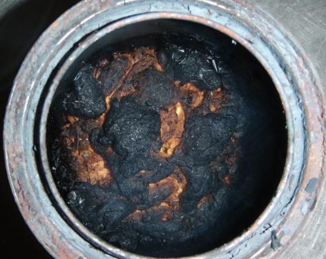
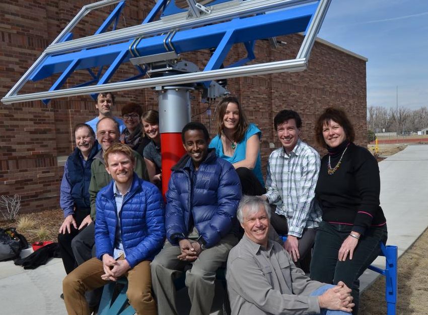
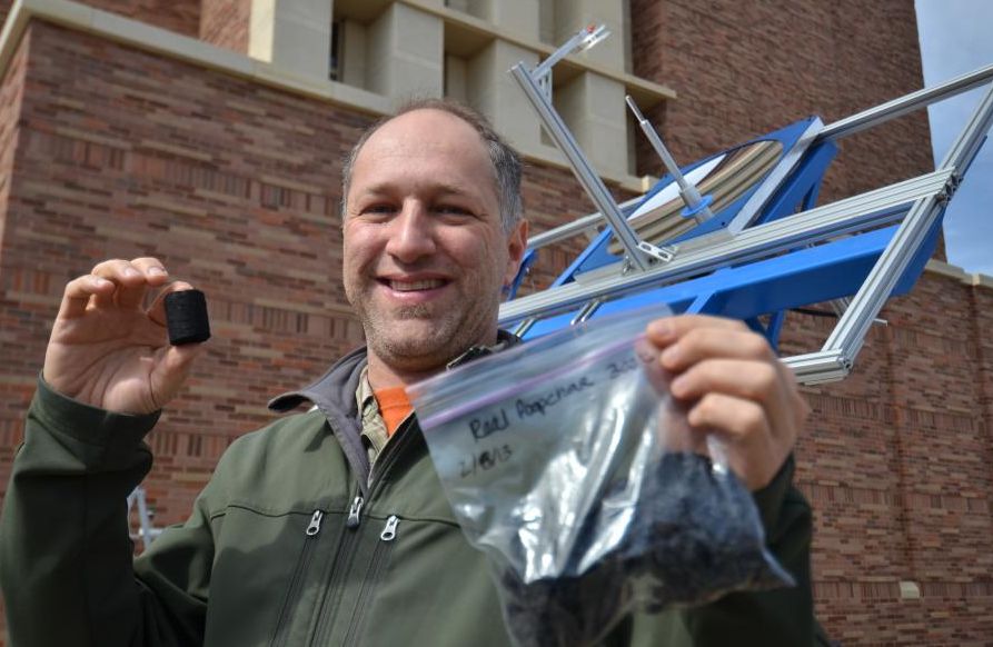
A University of Colorado research group led by Alan Weimer has taken on the challenge of “Reinventing the Toilet.” In September of 2012, this group (with Principal Investigator Karl Linden) received funding from the Bill & Melinda Gates Foundation to develop a novel toilet that produces char from waste using solar energy. This toilet, the Sol-Char, is a waterless, self-contained toilet that can function completely off the grid by capturing readily available solar energy. Concentrated sunlight is delivered to fiber optic bundles located at the focus of parabolic concentrators; the fiber optic cables are fed to the reaction compartment of the Sol-Char where the various individual cables are terminated at an outer or “solar” lid positioned over the waste collection container. The innovative transmission of solar power illuminates the inner collection container and disinfects the waste though convection and radiation heat transfer. The reaction compartment comprises two containers that are alternated between “collection” and “reaction” modes via a simple carousel system that can be automated (powered with photovoltaic energy) or manually controlled. The reactor is designed to achieve high temperatures with minimal heat loss due to specially designed insulation and produces a safe and useable product. The Sol-Char toilet can be developed for virtually any number of users with solar power input scaled accordingly. Means for innovative odor control and final product storage/ collection (for later use as a soil amendment) are also being developed as a part of the Sol-Char.
A University of Colorado research group led by Alan Weimer has taken on the challenge of “Reinventing the Toilet.” In September of 2012, this group (with Principal Investigator Karl Linden) received funding from the Bill & Melinda Gates Foundation to develop a novel toilet that produces char from waste using solar energy. This toilet, the Sol-Char, is a waterless, self-contained toilet that can function completely off the grid by capturing readily available solar energy. Concentrated sunlight is delivered to fiber optic bundles located at the focus of parabolic concentrators; the fiber optic cables are fed to the reaction compartment of the Sol-Char where the various individual cables are terminated at an outer or “solar” lid positioned over the waste collection container. The innovative transmission of solar power illuminates the inner collection container and disinfects the waste though convection and radiation heat transfer. The reaction compartment comprises two containers that are alternated between “collection” and “reaction” modes via a simple carousel system that can be automated (powered with photovoltaic energy) or manually controlled. The reactor is designed to achieve high temperatures with minimal heat loss due to specially designed insulation and produces a safe and useable product. The Sol-Char toilet can be developed for virtually any number of users with solar power input scaled accordingly. Means for innovative odor control and final product storage/ collection (for later use as a soil amendment) are also being developed as a part of the Sol-Char.
Solar-driven
thermal toilet with biochar production (video)
https://www.youtube.com/channel/UCepQCZ2v5mZ3YSMGWsYZ-4A
Sol-Char Toilet Channel
https://www.youtube.com/watch?v=D8Mjr6_Rea8
Chip Fisher: Demonstration of Sol-Char Toilet Exhibit (University of Colorado Boulder, USA), P. 2
https://www.youtube.com/watch?v=sDehxJBknFg
Solar-driven thermal toilet with biochar production (Scott Summers, University of Colorado)
https://www.youtube.com/watch?v=uaPsdpSoohI
Overview of the sol-char toilet
https://vimeo.com/129238329
Sol-Char Toilet - Overview on Vimeo
https://www.researchgate.net/publication/267308950_337056_The_Sol-Char_Toilet_Concentrated_Solar_Power_Transported_By_Fiber_Optics_for_Pyrolysis_of_Human_Waste_to_Biochar
Conference: 13 AIChE Annual Meeting
The Sol-Char Toilet: Concentrated Solar Power Transported By Fiber Optics for Pyrolysis of Human Waste to Biochar
Abstract
Currently, 2.6 billion people on the planet do not have access to adequate sanitation and many communities in the developing world have neither the facilities nor the resources to properly treat human waste, leading to open defecation posing enormous public health risks as well as issues related to individual dignity and safety. Sanitation is not a problem unique to developing countries – modern sanitation processes are also unsustainable due to their often massive requirements for energy and water. The Sol-Char Toilet, a solar waste treatment technology developed at the University of Colorado Boulder, takes advantage of our most abundant renewable resource: the sun. In the Sol-Char Toilet, concentrated solar power (CSP) is transmitted through fiber optic cables to drive pyrolysis of human waste, converting a hazardous and unusable material to biochar. Biochar is a carbonized solid product of thermal biomass decomposition consisting largely of condensed aromatic zones that when applied as a soil amendment imparts agronomic benefits and is recalcitrant over a long timescale (102 – 103years). Biochar presents a solution relevant to the world today: reducing greenhouse gas emissions by sequestering carbon in biochar for several hundreds of years or even millennia. The over-reaching goal of the project is to develop a cost-effective, self-contained, and sustainable sanitation process by which human waste can be converted to useful products without connection to water, sewer or electricity. Sunlight is concentrated to nearly 2000 Suns by a parabolic mirror, directed into a fiber optic bundle, and routed to a solar hood that directly irradiates a pyrolysis reactor. Two identical reactor vessels are switched between a pyrolysis location under the solar hood and a toilet location via a rotating carousel mechanism, thus achieving a semi-continuous pyrolysis process during daylight hours. The Sol-Char Toilet prototype represents a novel application of CSP to the areas of environmental, sanitation, and reaction engineering. This presentation will focus on the design and operation of the 1 kW Sol-Char Toilet prototype designed and constructed at the University of Colorado at Boulder.
Sol-Char Sanitation
solchar@colorado.edu
1111 Engineering Center Drive
428 UCB
Boulder, CO 80309
Fax: 303-492-7317


US20130341175
Thermal Treatment System and Method
Thermal Treatment System and Method
Inventor: LINDEN KARL, et al.
A improved solar biochar reactor, system including the reactor, and methods of forming and using the reactors and systems are disclosed. The methods and system as described herein provide sufficient solar energy to a biochar reactor to convert animal waste or other biomass to biochar in a relatively cost-effective manner.
FIELD OF THE INVENTION
[0002] The present disclosure generally relates to thermal treatment systems and methods. More particularly, exemplary embodiments of the disclosure relate to systems and methods that use solar thermal processes to produce biochar from biomass.
BACKGROUND OF THE DISCLOSURE
[0003] Animal waste, such as human waste, can be an agent that carries and/or transmits infectious pathogens. Accordingly, such waste is often treated. Typical sewage treatment requires significant infrastructure and large-scale plants to treat the waste. Unfortunately, such systems may not be suitable in developing areas or where such large-scale, high-infrastructure systems are not practical.
[0004] Biochar reactors can be used to treat animal waste in areas where typical sewage treatment systems are not practical. A typical biochar production reactor relies on combustion of material to provide the necessary heat to convert biomass into one or more desired products. Unfortunately, use of combustion to heat the reactor may generate unwanted greenhouse gases.
[0005] Other bioreactors may rely on sunlight to produce requisite reactor temperatures for conversion of biomass to desired products. To achieve the requisite temperatures for such reactions, the solar reactors use concentrated sunlight. For example, a solar biochar reactor often includes a reactor located at a focus of an imaging optic, such as a parabola. Alternatively, solar furnaces or beam-down towers may be used; however, additional optical elements required for such systems increase the cost of the systems and the systems generally require sophisticated optical devices to achieve the suitably high solar concentrations.
[0006] Accordingly, improved solar biochar reactors and methods of forming and using the reactors are desired.
SUMMARY OF THE DISCLOSURE
[0007] Various embodiments of the present disclosure relate to improved solar biochar reactors, systems including the reactors, and methods of forming and using the reactors and systems. While the ways in which the various drawbacks of the prior art are discussed in greater detail below, in general, a method and system as described herein provide sufficient solar energy to a biochar reactor to convert animal waste or other biomass to biochar in a relatively cost-effective manner.
[0008] In accordance with various embodiments of the disclosure, a thermal treatment system includes a solar concentrator having an area of concentrated solar power, one or more fiber optic cables, the one or more fiber optic cables having a first end proximate*the area of concentrated solar power and a second end, a solar reactor coupled to the second end of the one or more fiber optic cables, the reactor comprising, a container to receive material to be treated, and insulating material surrounding the container. In accordance with various aspects of these embodiments, the system is used to treat animal waste, such as human waste. In accordance with further aspects, the thermal treatment system includes a urine diversion device. In accordance with further embodiments, the reactor is a hydrothermal carbonization reactor or a pyrolysis reactor. In accordance with yet additional aspects of these embodiments, the treatment system includes a rotating mechanism to expose a container to the one or more fiber optic cables. And, in accordance with further embodiments, the fiber optic cables are isolated from the reactor and the fiber optic cables may have fused ends. The system may further include a carousel to transfer containers between a treatment area and a collection area.
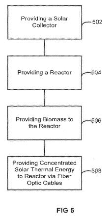
[0009] In accordance with further exemplary embodiments of the disclosure, a method to treat biomass includes providing a solar collector to obtain concentrated solar thermal energy, providing a reactor, providing biomass, such as animal waste, to the reactor, providing concentrated solar thermal energy to the reactor using one or more fiber optic cables, and treating the biomass with the concentrated solar thermal energy. In accordance with various aspects of these embodiments, the method further includes a step of rotating a carousel to expose the reactor or container to one or more fiber optic cables. In accordance with further aspects, the fiber optic cables that are used include fused ends. In accordance with further aspects, the step of treating the biomass with the concentrated solar thermal energy comprises using hydrothermal carbonization or pyrolysis. In accordance with yet further aspects, the method includes condensing water vapor. And, in accordance with yet further aspects, the method includes removing condensable tars within pyrolysis gas using a removable tar trap prior to further treatment or use of a gas. The method may also include removing odor causing compounds from the pyrolysis gas using one or more of a biochar and activated carbon packed filter bed.
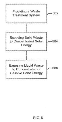
[0010] In accordance with yet additional exemplary embodiments of the disclosure, a method to treat animal waste includes providing a waste treatment system comprising a solar collector and a reactor, wherein the reactor receives concentrated solar energy from the solar collector, exposing solid waste to the concentrated solar energy in the reactor to produce char; and exposing liquid waste to one or more of concentrated and passive solar energy to treat the liquid waste. In accordance with various aspects of these embodiments, the method further includes a step of rotating a carousel to expose the reactor or a container therein to one or more fiber optic cables. In accordance with further aspects, the fiber optic cables that are used include fused ends. In accordance with further aspects, the step of treating the biomass with the concentrated solar thermal energy comprises using hydrothermal carbonization or pyrolysis. In accordance with yet further aspects, the method includes condensing the water vapor. And, in accordance with yet further aspects, the method includes removing condensable tars within pyrolysis gas using a removable tar trap prior to further treatment or use of a gas. The method may also include removing odor causing compounds from the pyrolysis gas using one or more of a biochar and activated carbon packed filter bed.
[0011] The system and method disclosed herein can be used to produce biochar from animal waste, such as human waste, using solar thermal processes, such as ultraviolet/thermal driven disinfection, hydrothermal carbonization, and/or pyrolysis. The system and method can be used for, e.g., solar-driven hydrothermal pyrolysis and treatment of mixed human waste, without need for intensive pre-drying, to produce a char that has advantages in soil applications for agriculture. In addition to treating waste and producing char, other valuable end products may be produced using the system and method described herein.
[0012] Both the foregoing summary and the following detailed description are exemplary and explanatory only and are not restrictive of the disclosure or the claimed invention.
BRIEF DESCRIPTION OF THE DRAWING FIGURES
[0013] The exemplary embodiments of the present invention will be described in connection with the appended drawing figures in which like numerals denote like elements and:
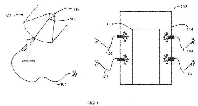
[0014] FIG. 1 illustrates a thermal treatment system in accordance with exemplary embodiments of the invention.
[0015] FIGS. 2A and 2B illustrate another thermal treatment system in accordance with additional embodiments of the invention.
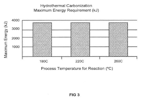
[0016] FIG. 3 illustrates hydrothermal carbonization energy requirements.
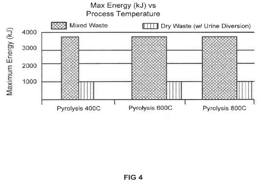
[0017] FIG. 4 illustrates energy vs. process temperature for mixed or dry waste.
[0018] FIG. 5 illustrates a method in accordance with further exemplary embodiments of the invention.
[0019] FIG. 6 illustrates another method in accordance with additions embodiments of the invention.
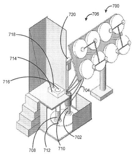
[0020] FIG. 7 illustrates yet another thermal treatment system in accordance with additional embodiments of the invention.
A improved solar biochar reactor, system including the reactor, and methods of forming and using the reactors and systems are disclosed. The methods and system as described herein provide sufficient solar energy to a biochar reactor to convert animal waste or other biomass to biochar in a relatively cost-effective manner.
FIELD OF THE INVENTION
[0002] The present disclosure generally relates to thermal treatment systems and methods. More particularly, exemplary embodiments of the disclosure relate to systems and methods that use solar thermal processes to produce biochar from biomass.
BACKGROUND OF THE DISCLOSURE
[0003] Animal waste, such as human waste, can be an agent that carries and/or transmits infectious pathogens. Accordingly, such waste is often treated. Typical sewage treatment requires significant infrastructure and large-scale plants to treat the waste. Unfortunately, such systems may not be suitable in developing areas or where such large-scale, high-infrastructure systems are not practical.
[0004] Biochar reactors can be used to treat animal waste in areas where typical sewage treatment systems are not practical. A typical biochar production reactor relies on combustion of material to provide the necessary heat to convert biomass into one or more desired products. Unfortunately, use of combustion to heat the reactor may generate unwanted greenhouse gases.
[0005] Other bioreactors may rely on sunlight to produce requisite reactor temperatures for conversion of biomass to desired products. To achieve the requisite temperatures for such reactions, the solar reactors use concentrated sunlight. For example, a solar biochar reactor often includes a reactor located at a focus of an imaging optic, such as a parabola. Alternatively, solar furnaces or beam-down towers may be used; however, additional optical elements required for such systems increase the cost of the systems and the systems generally require sophisticated optical devices to achieve the suitably high solar concentrations.
[0006] Accordingly, improved solar biochar reactors and methods of forming and using the reactors are desired.
SUMMARY OF THE DISCLOSURE
[0007] Various embodiments of the present disclosure relate to improved solar biochar reactors, systems including the reactors, and methods of forming and using the reactors and systems. While the ways in which the various drawbacks of the prior art are discussed in greater detail below, in general, a method and system as described herein provide sufficient solar energy to a biochar reactor to convert animal waste or other biomass to biochar in a relatively cost-effective manner.
[0008] In accordance with various embodiments of the disclosure, a thermal treatment system includes a solar concentrator having an area of concentrated solar power, one or more fiber optic cables, the one or more fiber optic cables having a first end proximate*the area of concentrated solar power and a second end, a solar reactor coupled to the second end of the one or more fiber optic cables, the reactor comprising, a container to receive material to be treated, and insulating material surrounding the container. In accordance with various aspects of these embodiments, the system is used to treat animal waste, such as human waste. In accordance with further aspects, the thermal treatment system includes a urine diversion device. In accordance with further embodiments, the reactor is a hydrothermal carbonization reactor or a pyrolysis reactor. In accordance with yet additional aspects of these embodiments, the treatment system includes a rotating mechanism to expose a container to the one or more fiber optic cables. And, in accordance with further embodiments, the fiber optic cables are isolated from the reactor and the fiber optic cables may have fused ends. The system may further include a carousel to transfer containers between a treatment area and a collection area.
[0009] In accordance with further exemplary embodiments of the disclosure, a method to treat biomass includes providing a solar collector to obtain concentrated solar thermal energy, providing a reactor, providing biomass, such as animal waste, to the reactor, providing concentrated solar thermal energy to the reactor using one or more fiber optic cables, and treating the biomass with the concentrated solar thermal energy. In accordance with various aspects of these embodiments, the method further includes a step of rotating a carousel to expose the reactor or container to one or more fiber optic cables. In accordance with further aspects, the fiber optic cables that are used include fused ends. In accordance with further aspects, the step of treating the biomass with the concentrated solar thermal energy comprises using hydrothermal carbonization or pyrolysis. In accordance with yet further aspects, the method includes condensing water vapor. And, in accordance with yet further aspects, the method includes removing condensable tars within pyrolysis gas using a removable tar trap prior to further treatment or use of a gas. The method may also include removing odor causing compounds from the pyrolysis gas using one or more of a biochar and activated carbon packed filter bed.
[0010] In accordance with yet additional exemplary embodiments of the disclosure, a method to treat animal waste includes providing a waste treatment system comprising a solar collector and a reactor, wherein the reactor receives concentrated solar energy from the solar collector, exposing solid waste to the concentrated solar energy in the reactor to produce char; and exposing liquid waste to one or more of concentrated and passive solar energy to treat the liquid waste. In accordance with various aspects of these embodiments, the method further includes a step of rotating a carousel to expose the reactor or a container therein to one or more fiber optic cables. In accordance with further aspects, the fiber optic cables that are used include fused ends. In accordance with further aspects, the step of treating the biomass with the concentrated solar thermal energy comprises using hydrothermal carbonization or pyrolysis. In accordance with yet further aspects, the method includes condensing the water vapor. And, in accordance with yet further aspects, the method includes removing condensable tars within pyrolysis gas using a removable tar trap prior to further treatment or use of a gas. The method may also include removing odor causing compounds from the pyrolysis gas using one or more of a biochar and activated carbon packed filter bed.
[0011] The system and method disclosed herein can be used to produce biochar from animal waste, such as human waste, using solar thermal processes, such as ultraviolet/thermal driven disinfection, hydrothermal carbonization, and/or pyrolysis. The system and method can be used for, e.g., solar-driven hydrothermal pyrolysis and treatment of mixed human waste, without need for intensive pre-drying, to produce a char that has advantages in soil applications for agriculture. In addition to treating waste and producing char, other valuable end products may be produced using the system and method described herein.
[0012] Both the foregoing summary and the following detailed description are exemplary and explanatory only and are not restrictive of the disclosure or the claimed invention.
BRIEF DESCRIPTION OF THE DRAWING FIGURES
[0013] The exemplary embodiments of the present invention will be described in connection with the appended drawing figures in which like numerals denote like elements and:
[0014] FIG. 1 illustrates a thermal treatment system in accordance with exemplary embodiments of the invention.
[0015] FIGS. 2A and 2B illustrate another thermal treatment system in accordance with additional embodiments of the invention.
[0016] FIG. 3 illustrates hydrothermal carbonization energy requirements.
[0017] FIG. 4 illustrates energy vs. process temperature for mixed or dry waste.
[0018] FIG. 5 illustrates a method in accordance with further exemplary embodiments of the invention.
[0019] FIG. 6 illustrates another method in accordance with additions embodiments of the invention.
[0020] FIG. 7 illustrates yet another thermal treatment system in accordance with additional embodiments of the invention.
[0021] It will be appreciated that elements in the figures are illustrated for simplicity and clarity and have not necessarily been drawn to scale. For example, the dimensions of some of the elements in the figures may be exaggerated relative to other elements to help to improve understanding of illustrated embodiments of the present invention.
DETAILED DESCRIPTION OF THE INVENTION
[0022] As set forth in more detail below, the present disclosure provides improved solar biochar reactors, systems including the reactors, and methods of forming and using the reactors and systems. The reactors, systems, and methods may be used to treat biomass, such as animal waste and convert the biomass to biochar, which may be used for various beneficial applications.
[0023] The systems and method described herein use concentrated sunlight to obtain desired operating temperatures within a reactor. In traditional solar thermal systems, the reactor or receiver is located at the focus of the imaging optic, which is typically a parabola. Several concepts have been proposed, and a few have been built, which utilize additional optical elements to redirect the concentrated beam to a more convenient location, such as on the ground level. These include solar furnaces and beam-down towers. Additional optical elements for this redirection drive up costs and require the use of sophisticated optical devices to achieve high concentrations. Thus, designing solar thermal reactors where their location is driven by process rather than optical requirements has not been a successful development path for large-scale applications. To overcome these issues, in accordance with various exemplary embodiments of the invention, concentrated sunlight is delivered via fiber optic cables from a concentrated source of sunlight to a reactor.
[0024] The concept of solar concentrators using fiber optics for delivery of sunlight was first proposed over thirty years ago (Kato 1976); however, the successful demonstration of this approach was only made possible after the development of improved fiber optic technology for communications. The growth in use of fiber optics for a number of applications outside of solar enabled glass fibers of sufficient purity and low enough cost has spurred their use in solar thermal systems (Peill 1997, Zik 1999, Feuermann 1999). While certainly not a mainstream solar thermal approach, fiber optics-based systems have progressed enough to warrant a recent review article (Kandilli 2009). Small-scale demonstrations have been very encouraging and show the potential for both good performance and achievement of high temperature (Nakamura 2011).
[0025] FIG. 1 illustrates a thermal treatment system 100 in accordance with exemplary embodiments of the disclosure. Thermal treatment system 100 includes a reactor 102, one or more fiber optic cables 104, a solar concentrator 108, having an area of concentrated solar power 106, and a container 110. In the illustrated example, concentrated sunlight is delivered to reactor 102 via one or more fiber optic cables 104 (e.g. a fiber optic bundle) located at or proximate area of concentrated solar power 106 (e.g., the focus of a parabolic concentrator 108) as shown in FIG. 1. Fiber optic cable 104 is fed to reactor 102 of the system 100, where the various individual cables may terminate at, e.g., the outside of the reactor or lid (e.g., between insulating material 114 and container 110). In this case, waste container 110 is illuminated via radiation heat transfer, and container 110 is contained within insulated reactor 102. System 100 may additionally include a mirror 112 to concentrate the solar energy. A mirror size may range from, for example, about 2 m<2 >to about 100 m<2 >or about 2 m<2 >to about 50 m<2>. Compared to typical solar thermal reactors, where heat losses to the ambient environment are driven by radiation and convection, the illustrated reactor can achieve high temperatures with low solar input by limiting heat losses to conduction in the surrounding ground. In accordance with exemplary embodiments of the invention, at least some of the insulation may be movable. For example, a solar lid on reactor 102 may be coupled to fiber optic cables, and the lid can be removed or raised as material is collected in reactor 102 and then closed during treatment of the biomass material. See, e.g. system 700, below.
[0026] A design of the solar concentrator may depend on a variety of factors, based on, for example, physical properties of the biomass or waste stream to be treated. An estimate of the energy input required for a family of 4 is from about 4,000 to about 14,000 kJ, depending on specific reaction process and the temperature of that process. Energy inputs for families of 10 and shared toilets for 50 individuals are shown in Table 1. If 3 hours per day of solar operation are assumed, the power requirement is about 1300 W of net input to the reactor (using energy estimates for hydrothermal carbonization at 180° C. and accounting for conduction loss to the surrounding ground). For readily achievable values for concentrator reflectivity, secondary reflectivity, intercept factor, fiber bundle fill factor, fiber Fresnel reflections and fiber transmission, the solar efficiency can be estimated to be about 0.46. This efficiency with an average direct irradiance of 800 W/m<2 >over the operation period requires a mirror area of around 3.6 m<2 >(diameter about 2.1 m). This size is certainly small enough for use in a single family, developing community setting. Note that with higher efficiency, longer processing time or lower energy requirements, this size could be significantly reduced. A larger scale system supporting 50 people could use an area of about 46 m<2>. This could be achieved with either multiple smaller units or a decreasing number of larger diameter concentrators. While a smaller family scale system may be desirable in some cases, intermediate and large-scale systems may be scaled for business management applications, where operations and maintenance can be integrated for savings.
TABLE 1
Estimated Maximum Energy Required and Solar Area
Mixed Dry
HTC Pyrolysis Pyrolysis
4 person basis
Max energy (kJ) 13911 13341 4064Solar Area (m<2> ) 3.6 3.6 1.3
10 person basis
Max energy (kJ) 34778 33353 10160Solar Area (m<2> ) 8.9 8.9 3.0
50 person basis
Max energy (kJ) 173889 166764 50802Solar Area (m<2> ) 44.5 43.9 14.7
[0027] The system and method described herein may be particularly suitable for a developing community environment. In this case, local materials can be used. The scale of such a system may depend on the degree to which the local labor force can be trained to build and operate the system, the availability of local materials, the cost for off-site versus local fabrication, and the overall economics of the concept as a business venture. Reactor 102 and solar receiving container 110 can be designed with solar power input scaled accordingly.
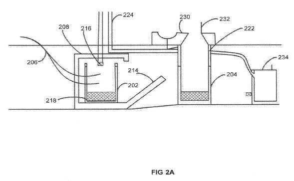
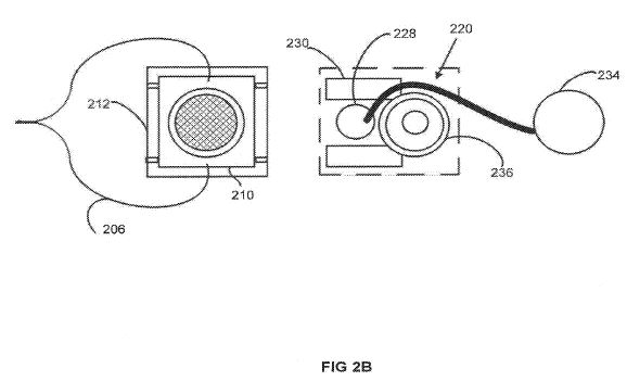
[0028] FIGS. 2A and 2B illustrate a system 200 including a first container 202 and a second container 204, fiber optic cable 206, a reactor 208, including insulation 210, a biochar removal door (insulated, sealed, latched shut) (212), a feedstock entrance door with tracks (insulated sealed, latched shut) 214, a safety pressure release valve for pyrolysis gases 216, waste inside the reactor 218, an example squat plate in dashed lines 220, a receiver 222, a vent tube 224 connected to a wind driven ventilator, a urine diverter 228 (included for dry pyrolysis toilet), a foot stepping platform 230, a foot operated lid for the waste input hole 232, a urine collection container 234 (e.g., for a dry pyrolysis reactor system), and a waste receiver position 236, where container 204 is in a collection position and waste receiver 202 in a treatment position. Systems in accordance with the present disclosure may also include a rotating mechanism to expose a reactor or portions thereof (e.g., a container) to one or more fiber optic cables.
[0029] In the illustrated system, first container 202 and a second container 204 can be switched between “collecting” and “treatment” positions, as shown in FIG. 2A. The containers may be switched using, for example a carousel to move the reactors—e.g., from the collection position to the treatment position. Although illustrated with only two containers 202, 204, systems in accordance with the present disclosure may include additional containers, which may be, for example on a carousel or track for easy moving between a treatment position and a collection position. Further, although not illustrated, systems in accordance with the present disclosure may include a trap for collecting condensing water vapor from a pyrolysis treatment rector, a removable tar trap for removing condensable tars within a pyrolysis reactor, and/or biochar and/or activated carbon to remove or filter odor-causing compounds.
[0030] Urine collected in urine collection container 234 may be treated using solar energy from one or more fiber optic cables 206 or natural or otherwise concentrated sunlight—e.g., urine may be heat treated to temperature and time combinations that can render it disinfected. Alternatively, a means for continuously treating human fecal sludge using a solids-conveying system where an outer solar tube heats up an inner sheathed auger to produce char may be used. Alternatively, the urine could be treated using a thin film flow reactor using germicidal UV light (254 nm). Or, heat energy from the condensation of water vapor generated during solid waste treatment can be used to heat the urine to temperature and time combinations that can render it disinfected. In accordance with other aspects, a jacketed recirculation of urine around a pyrolysis reactor can be used to heat treat urine to temperature and time combinations that can render it disinfected.
[0031] When a full collection container (e.g., container 202) is transferred (e.g., via a track and wheel system to a treatment (e.g., pyrolysis) zone, door 214 can be shut and sealed with a handle for the user, e.g., similar to a locking freezer door. The pyrolysis zone includes a gas discharge hole above the waste-filled collection container for product gases, roughly 14.2 m<3 >of steam and 0.66 m<3 >of methane per day per family of four, that can be utilized onsite for heating and/or driving electrical generators for lighting and other minor electrical loads. For hydrothermal carbonization (1-ITC), the pyrolysis zone gas discharge can be fitted with a 20 psig pressure-relief valve to allow the reactor to maintain suitable reaction conditions of 180-220° C. and 18 psig. Fiber-optic cables carrying concentrated solar light can be fed into the walls of the pyrolysis zone (e.g., though walls 210), or through a lid of a container to heat the container up to reaction temperature ̃400° C. for conventional pyrolysis.
[0032] FIG. 7 illustrates another system 700 in accordance with exemplary embodiments of the invention. Similar to systems 100 and 200, system 700 includes a reactor 702, fiber optic cables 704, an area of concentrated sunlight 706, containers 708, 710, a carousel 712 to switch containers 708, 712 between a collection area and a treatment area, a toilet 714, optionally including separate areas for solid 716 and liquid 718 collection, and a vent 720. All of the components of system 700 may be the same or similar to corresponding components of systems 100 and 200 as described herein.
[0033] An estimated maximum energy requirement for the solar powered pyrolysis reaction is at about 14,000 kJ, assuming the system is used by 4 people per day (one household) operating at 34.7 psia and 180° C. An estimated maximum energy requirement, for charring one person's daily waste at varying temperatures is shown in FIG. 3 for hydrothermal carbonization and in FIG. 4 for pre-dried and mixed pyrolysis in. Human waste is comprised mostly of water, 65% or more, which is energy intensive to heat and boil due to the high heat capacity of water. Approximately 12,800 kJ accounts for heating up wet feces to the boiling point of water and boiling the water off. The balance of heat accounts for estimated heat loss through the walls of the reaction zone to the surroundings. It is important to note that this energy estimate does not include any energy gained back from the exothermic pyrolysis reaction which would be driven by any air/O2 in the system. Exclusion of this energy return allows one to determine the maximum power requirement to achieve the reaction temperature. Table 2 lists assumed physical properties of an exemplary system, such as system 100 or 200.
TABLE 2
Summary of physical properties and mass flow rates of incoming waste streams
Property Value Units
Mass flow rate feces per person 400 g/day
Mass flow rate urine per person 1017.5 g/day
Estimated specific heat capacity of wet feces 5 J/g-K
Estimated specific heat capacity of dry feces 1 J/g-K
Specific heat capacity of water 4.1813 J/g-K
Mass fraction of water in feces 0.75
Mass fraction of solids in feces 0.25
Heat of vaporization for water 2.257 kJ/g
[0034] The product gas stream of the system can be monitored in situ using a gas chromatograph mass spectrometer (GC-MS). Gas products of pyrolysis are predominately CO2 and CH4 but other noxious gases will likely be present in dilute concentrations and to ensure that the reactor gases do not pose an environmental hazard to the user, adjustments can be made to the oxygen content of the reaction environment. Thus, a usable product for heating requirements in the single-user facility or at the local community level can be produced. The system may include additional controls to ensure proper temperature, pressure, and solar radiation control for the solar reactor.
[0035] Exemplary materials of construction for the reactor include aluminum and stainless steel, both readily available and affordable. Reaction temperatures are unlikely to reach temperatures above the melting points of such metals or alloys. Additionally or alternatively, corrosion resistant materials such as stainless steel (Inconel, for example) that can also withstand high temperatures may be used. Several options for insulation may be suitable to reduce the energy losses to the environment surrounding the reactor (e.g., soil). Viable options include typical fiberglass insulation, ceramic fiber insulation (alumina or silica), and aerogels.
[0036] Design of the reactor may depend of a variety of factors, such as chemistry, namely hydrothermal carbonization (HTC) and conventional pyrolysis, energy requirements, soil amendment characteristics and optimal use of nutrients as described below. Hydrothermal carbonization requires lower reaction temperatures, 180-220° C. but pressures approaching 20 psig while conventional biomass pyrolysis takes place at atmospheric pressures but much higher temperatures, 400-800° C. (Libra, 2011). The design of an HTC reactor addresses pressure and temperature control requirements. At increased pressures and temperatures, failure of the reactor wall could lead to a dangerous release in pressure. In both HTC and pyrolysis reactors, biomass conversion is an exothermic process, which carries increased risk of thermal runaway. Accordingly, reactor design accounts for the thermal properties of the respective system, including heat transfer, fluid flow, and time-dependent temperature profiles. Thermocouples, temperature controllers, and data acquisition software such as LabView or Matlab can be used to aide in the reactor design. Real-time analysis of the gas species generated during pyrolysis is used to optimize reaction conditions and, ultimately, the utility of the biochar. These data are obtained with the use of GC-MS. Evaluations of HTC and conventional pyrolysis can balance energy requirements with nutrient recovery as well as product quality and utility of by-product gases.
[0037] An exemplary system may include a pyrheliometer—a device that accurately measures direct solar irradiance. Solar irradiance measurements may be desired to the optimization of the solar concentrator equipment and sun-tracking algorithms. Solar tracking can be accomplished via two pathways: closed- and open-loop control. Closed-loop control utilizes a sun-sensor, which is made up of several small cells around the base of a rod. Throughout the day, the shadow cast down onto the array changes and indicates the position of the sun in the sky. This system would be more expensive than open-loop but has the advantage of feedback control and less risk of error. The control system also includes a resolver or optical encoder to translate the data from the tracking system into a command for motors to adjust the position of the solar concentrator(s). Open-loop control involves motors that will adjust the solar collectors according to a pre-determined program based on latitude, longitude, date and time. This approach, though more affordable, has a high risk of error and may require extra maintenance and monitoring from a trained technician. If solar tracking is desired, a small PV system may be used to power the tracking motor.
[0038] Biochar, a value added product from the system and method described herein, has been utilized to improve agricultural soil fertility, sequester carbon, control transport of environmental contaminants, and remove pesticides as a water filter media (although the latter is not envisioned as a use for the latrine waste biochar). The processes for generation of biochar also produce gases that can be used as cooking and heating fuel or supplemental energy for the biochar production.
[0039] Biochar applied to soil can improve soil structure, water retention and lower the acidity of the soil (Winsley, 2007). Biochar material has high surface area which is capable of supporting microbiota and encouraging healthy biological activity in the soil. These microbiota act as catalysts in reducing nitrogen loss, making nutrients more available to plants. Biochar is made up of 70-80% carbon, a much more condensed quantity when compared to the biomass it is generated from. When it is placed in the soil, this carbon is permanently sequestered in this highly stable form for a net reduction of greenhouse gas emissions (Roberts, 2010). For this reason it has been proposed as an avenue for carbon sequestration credits and therefore these systems could be proliferated (multiplied to many locales) by revenue generated from selling carbon credits.
[0040] Two major factors that may impact the quality of a biochar include manufacturing conditions and the biomass (feedstock) used. Exemplary manufacturing methods include pyrolysis and hydrothermal carbonization (HTC) as these achieve high mass yield during the process and generate biochar with characteristics good for soil amendment (Funke & Ziegler, 2010; Winsley, 2007; Kumar & Gupta, 2009). Pyrolysis of animal waste and wastewater sludge have shown to generate effective biochar for soil amendments; more effective in agricultural field studies than cellulose/wood based feedstock (Meyer et al., 2011; Libra et al., 2011; Steinbeiss, 2009). A potential for generation of fuel from the gases created during pyrolysis has also been documented (Ro et al., 2010). One study has been conducted which evaluates pyrolysis of fresh human waste (US Army, 1974). This study verified that human waste could be converted into a more compact and sterile material.
[0041] For the reactor design, HTC has the advantage that no energy intensive pre-drying is necessary and because the waste is mixed (the waste includes solids and urine) it is thought that nutrients from the urine (as urine contains at least triple the mass of N, P and K of feces) will be taken up by the biochar, which would produce a nutrient enhanced biochar. Dry pyrolysis does not require a pressure rated reaction vessel and can be designed to use passive solar drying or rapid dewatering as the first phase of the solar pyrolysis process.
[0042] In the case of HTC, biochar can be generated in a pressure-rated metal reaction vessel and heated to the desired temperature under autogeneous pressure. The temperatures may range from about 150-300° C., with 200° C. expected to be optimal (Libra et al., 2011). The residence times at these temperatures range from about 10 to 90 minutes. For dry pyrolysis, the wet urine and fecal material can be collected in an open vessel and placed in an oven to be heated to the desired temperature. Dry pyrolysis will require higher temperatures between about 400-800° C. and the residence time will also be much greater because pyrolysis cannot begin until the liquid is evaporated away. Once the feedstock is dried to constant mass, subsequent pyrolysis times range from about 30 to 90 minutes.
[0043] Ultimate and proximate analysis of the char can be conducted, including C, N, H, S, elemental analysis, fixed carbon, moisture content, volatile matter, and ash content. Macro and micronutrients can be quantified by following ashing-digestion protocol and analyzing the samples with an Axial Spectrometer (P and K can be measured using an inductively coupled plasma (ICP) atomic emissions spectroscopy (AES)). The biochar product can be analyzed by field emission scanning electron microscopy (FESEM) to examine pore structure. Surface area of all resulting biochar can be measured using the method of Brunauer, Emmett and Teller (BET). Thermogravimetric analysis (TGA) can be conducted as well as Fourier Transform Infrared (FTIR) analysis in order to isolate the types of functional groups before and after charring.
[0044] It is expected that the biochar yield will be 45-60% for HTC and 20-35% for dry pyrolysis. The oxygen to carbon (O/C) ratio should decrease in the conversion to biochar and the HTC generated biochar will have a higher O/C ratio compared to that of dry pyrolysis. The abundance of oxygen-rich organic compounds on the surface of the biochar generated by HITC adds cation exchange capacity (Kumar, 2011). In general a successful soil amendment should have an O/C ratio of less than 0.2 (Spokas, 2010), a volatile matter content less than 20% (Deenik, 2010), and a BET SA of at least 15 m<2>/g. (Brewer et al., 2011). Additionally, biochar successful as a soil amendment should exhibit a low intrinsic pH, high aromaticity, and lower ash content (Brewer et al., 2011). It is expected that higher amounts of nitrogen and phosphorus will be found in the HTC biochar as the urine is combined with feces. There is evidence of higher nitrogen content with wastewater sludge processed by HTC, but never with mixed fresh human excreta (Hossain et al. 2010). The option of separation of urine and feces may determine biochar quality, energy requirements and nutrient recovery optimization.
[0045] Pyrolysis of the combined urine and feces may mineralize the nutrients found in human excreta, such as nitrogen, phosphorus, and potassium, making them bioavailable for plants. At a biochar yield of 45%, an ideal 9 g of nitrogen and 1 g of phosphorus could be recovered per person per day through the HTC process (Torondel, 2010). Nitrogen and phosphorus recovery from urine alone has been demonstrated through the use of solar thermal evaporation from exposure to direct sunlight. A pilot-scale study evaporating 50 L of undiluted urine yielded 360 g of fertilizer (2% nitrogen and 2% phosphorus by weight), equaling approximately 0.2 g of nitrogen and 0.2 g of phosphorus per person per day. The urine-derived fertilizer led to biomass yields and nutrient uptakes comparable to those from commercial fertilizers (Antonini 2012).
[0046] Potential benefits of urine separation can be weighed alongside the added cost of separate urine purification. In the event that urine is separated for nutrient recovery, pathogens may desirably be inactivated by heat. This scenario may also consider fecal contaminants due to the potential for fecal cross-contamination during urine collection (WHO, 2006). Enteric viruses are killed rapidly at temperatures of 60° C. Entamoeba hystolytica cysts and hookworm eggs are killed after five minutes at 50° C. Schistosome eggs require one hour at 50° C. and Taenia eggs 10 minutes at 59° C. Bacteria such as Vibrio cholerae and E. coli are killed rapidly above 55 or 60° C. respectively and Salmonella requires 15 to 20 min at 60° C. (Feachem 1980, Gottas 1956). Therefore, in the event that urine is separated for nutrient recovery, a temperature of at least 65° C. can be used for pathogen inactivation. This temperature is practical to achieve outside of the reactor through a passive solar thermal process. Additionally, flowing source-separated urine through a parabolic reflector could take advantage of natural UVB rays from the sun for pathogen inactivation (Mbonimpa 2012). Exemplary systems include thermal and/or natural UV inactivation of pathogens.
[0047] Both the initial human waste and biochar produced can be tested for indicator organisms of known pathogens. The material can be diluted into suspension and inoculated with the appropriate culture for each type of bacteria, including mesophile, thermophile, the organic decomposition bacteria, coliform bacteria, fecal coliform, E. coli salmonella and enterococci. Additional testing can be conducted for regrowth of indicator organisms during storage of biochar and more advanced testing for thermotolerant spores and cysts. Reactor exhaust can be analyzed for major hydrocarbons, sulfur containing gases, carbon monoxide, carbon dioxide and higher heating values. This analysis can be done with a GC-MS. This may provide information regarding whether the gases generated in either method present a health risk to the user or if they can be effectively harnessed as an energy source.
[0048] Various factors that can improve the performance of the system include: the tracking performance, reaction time, and insulation. In accordance with exemplary embodiments, the system exhibits hygienic reliability in terms of disinfecting waste on a consistent manner under a given environmental condition without the need for daily adjustments. An exemplary system also provides safe thermal, pressure and gaseous conditions by monitoring these inside the user compartment of the system.
[0049] Individual components which may be optimized for performance and cost include the solar collectors, any necessary tracking system, the reaction chamber, and the biochar production process. Additionally the biochar may be evaluated for soil amendment capabilities as well as nutrient value.
[0050] In evaluating the cost of a waste treatment system, a life cycle approach may be taken that considers not just construction costs, but also costs related to the sustainable delivery of a sanitation service. The system may be maintained to ensure that the service level remains the same as originally intended. Thus “costs” refer to expenditures incurred by the household or community (in case of the public toilet/system) for construction, operation and maintenance, and rehabilitation. This analysis helps one understand cost drivers so as to enable more cost effective service delivery. The benefits, which include elimination of costs associated with emptying, transporting, treating and disposing of traditional latrine human waste material as well as the value added material can be balanced against the costs of the system.
[0051] Table 3 shows cost estimates for system components, annualized and reported as a cost per person per day (6% discount rate and 20 year life). The scenarios analyzed range from household systems (for 4 and 10 individuals) to shared community systems (50 individuals). An estimate of the cost of small-scale solar concentrator systems using fiber optics is in the range of $200-500/m<2 >with an average of $350/m<2 >used in the calculations. The size and cost associated with the solar concentrator system for each biochar production method are shown in Table 3. Other system costs include the solar reactor, toilet base structure and superstructure. The cost estimate for the reactor associated with each system size depends on the desired temperature of reaction and orientation/automation of the collection area below the toilet. Assuming a reactor design without costly automation and with the use of aluminum or stainless steel; a system that serves 4 people is estimated to cost $230 for aluminum or $545 for stainless steel. A system serving 50 people would require a larger reactor for pyrolysis and is estimated at $700 for aluminum or $1635 for stainless. The construction of the collection area and the platform on which to stand in the bathroom can be designed and built out of local materials, e.g., reinforced concrete and brick/mortar; estimated at $100. The superstructure can be largely up to the users, but could likely be safe and private for less than $50. Table 3 shows that the final cost per person per day for these toilet systems are in the range of $0.03-0.10, indicating that the system has a very feasible economic outlook.
TABLE 3
Solar Energy and Capital Cost Estimates
Mixed Dry
HTC Pyrolysis Pyrolysis
4 person basis
Max energy (kJ) 13911 13341 4064Solar Area (m<2>) 3.6 3.6 1.3Solar Cost @$350/m<2>
$1,257 $1,253 $438
Additional Toilet Costs $380 $380 $380
Total Capital Costs $1,637 $1,633 $818
Annualized Cost $143 $142 $71
Cost per person per day $0.10 $0.10 $0.05
10 person basis
Max energy (kJ) $34,778 $33,353 $10,160Solar Area (m<2>) $9 $9 $3Solar Cost @$350/m<2>
$3,129 $3,101 $1,061
Additional Toilet Costs $380 $380 $470
Total Capital Costs $3,509 $3,481 $1,531
Annualized Cost $306 $303 $133
Cost per person per day $0.08 $0.08 $0.04
50 person basis
Max energy (kJ) $173,889 $166,764 $50,802Solar Area (m<2>) $45 $44 $15Solar Cost @$350/m<2>
$15,582 $15,351 $5,142
Additional Toilet Costs $850 $850 $850
Total Capital Costs $16,432 $16,201 $5,992
Annualized Cost $1,433 $1,412 $522
Cost per person per day $0.08 $0.08 $0.03
[0052] The value of the products produced can also be factored into the economic picture. Biochar is incorporated at a conservative price of $57 per ton, based on biochar without any nutrient content (McCarl et al., 2008). Assuming 400 g of feces per person and a 50% mass yield during the pyrolysis process, a daily value for biochar was calculated. It was calculated that 0.17 m<3 >of methane is produced per person per day and this added value is incorporated into Table 4 at a cost of $80 per 1,000 m<3 >(IndexMundi, 2012). In the case of urine diversion and purification, the product has a high nutrient value and a current price of $506/ton ammonium nitrate (34% N) and $665/ton of a 45% super phosphate (USDA 2012). Table 4 shows the overall value of the products produced in one day from the system designs described herein.
[0053] The technology can serve individual families but additionally could be more economical in peri-urban communities. Depending on the value of the value added products, shared community toilets could generate a large amount of nutrient infused biochar as well as be a site for additional community services such as a kitchen, served by the flammable gases produced during the pyrolysis process. Additionally, maintenance could be paid for by biochar or nutrient sales to rural areas, carbon credits associated with biochar and toilet system user fees.
TABLE 4
Value Added Product revenue.
Number of users: 4 10 50
Daily Biochar Value $0.01 $0.03 $0.13
Daily Methane Value $0.05 $0.14 $0.68
Daily Nutrient Value $0.07 $0.16 $0.82
[0054] The alternatives for the system design desirably include ease of use and maintenance, safety, affordability, and cultural appropriateness in regards to sanitation practices. A squat or a pedestal/sitting toilet design can be used depending on the cultural preference of end users. For the dry pyrolysis application, a urine diversion variant toilet can be used. The toilet seat may have a slightly elevated position above the floor to minimize water or other cleaning liquid entering the receiver/reactor through the input holes. Foot operated hole seals may be provided to minimize odor and help keep liquid out. A latrine floor may be made of smooth, polished, and durable materials to minimize odor causing adsorption and facilitate cleaning (Rieck, Muench, 2011). Floor drains may be provided to avoid the possibility of reactor/receiver area flooding as some users may utilize the restroom as a bath/shower space for lack of other space. Wind driven ventilation may be used to keep odor to an acceptable level. If desired, however, wood ash, lime, sawdust, soil, etc. can be used to cover fresh excreta. The user may slide/guide the reactor/receiver to the location of the reactor lid and secure the lid in place. This can be done routinely, e.g., every evening after transferring the pyrolysis end product to storage for later sale/use. The use of guides to move the reactor/receivers reduces accidental spilling of raw excreta. For the safety of the user, a temperature measurement unit may be installed to ensure that the reactor contents are cool enough to open. Periodically the user may be expected to replace the o-ring seals that help maintain a pressure seal for the reactor.
[0055] Turning now to FIG. 5, a method 500, which has been described above, is illustrated. Method 500 includes the steps of providing a solar collector to obtain concentrated solar thermal energy (step 502), providing a reactor (step 504), providing biomass to the reactor (step 506), providing concentrated solar thermal energy to the reactor using one or more fiber optic cables, (step 508) and treating the biomass with the concentrated solar thermal energy (step 508). Step 502 may include providing any suitable solar collector, such as concentrator 108. Step 504 may include providing any suitable reactor, such as reactor 102, 208, or 702. Providing biomass, step 506, may include, for example, providing animal waste, such as human waste, to the reactor. Concentrated solar thermal energy is provided to a solar reactor during step 508 using the techniques described herein—e.g., using fiber optic cables with fused fiber ends, terminating the end of the fibers prior to reaching the container, and the like. Method 500 may additionally include additional steps, as described herein, including rotating a carousel to expose the reactor to one or more fiber optic cables, using hydrothermal carbonization or pyrolysis, removing condensable tars within pyrolysis gas using a removable tar trap prior to further treatment or use of a gas, removing odor causing compounds from the pyrolysis gas using one or more of a biochar and activated carbon packed filter bed, and separately or not treating urine.
[0056] FIG. 6 illustrates another method 600 in accordance with yet additional embodiments of the invention. Method 600 includes providing a waste treatment system comprising a solar collector and a reactor (step 602), wherein the reactor receives concentrated solar energy from the solar collector, exposing solid waste to the concentrated solar energy in the reactor to produce char (step 604); and exposing liquid waste to one or more of concentrated and passive solar energy to treat the liquid waste (step 606). The steps of method 600 may employ any of the corresponding techniques described herein. For example, step 602 may include providing a system as described in connection with FIG. 1 or FIG. 2A or 2B. Step 604 may include exposing solid waste in a container to concentrated sunlight as described in connection with FIGS. 1, 2A and 2B. And step 606 may include any of the urine treatment techniques described herein.
[0057] The present invention has been described above with reference to a number of exemplary embodiments and examples. It should be appreciated that the particular embodiments shown and described herein are illustrative of the exemplary embodiments of the invention and its best mode, and are not intended to limit the scope of the invention. For example, although the invention has been described in connection with a system and method for treating human waste, the system and method may be used to treat other forms of animal waste. It will be recognized that changes and modifications may be made to the embodiments described herein without departing from the scope of the present invention. These and other changes or modifications are intended to be included within the scope of the present invention.
REFERENCES
[0000]
Brewer, C. E., Unger, R., Schmidt-Rohr, K., Brown, R. C., 2011. Criteria to Select Biochars for Field Studies based on Biochar Chemical Properties. Bioenerg. Res. 4, 312-323.
Bridle T R, Pritchard D. Energy and nutrient recovery from sewage sludge via pyrolysis. Water Sci Technol. 2004; 50(9): 169-75
Chen, B., Zhou, D., Zhu, L., 2008. Transitional adsorption and partition of nonpolar and polar aromatic contaminants by biochars of pine needles with different pyrolytic temperatures. Environ. Sci. Technol. 42, 5137-5143.
Deenik J L, McClellan T, Goro U, Antal M J, Campbell S (2010) Charcoal volatile matter content influences plant growth and soil nitrogen transformations. Soil Sci Soc Am J 74:1259-1270
Etter, B., Tilley, E., Khadka, R., Udert, K. M. Low-cost struvite production using source-separated urine in Nepal. Water Research, Volume 45, Issue 2, January 2011.
Feuermann, D. and J. M. Gordon, “Solar Fiber-Optic Mini-Dishes: A New Approach to the Efficient Collection of Sunlight.”, Solar Energy Vol. 65, No. 3, 159-170, 1999.
Funke, A., Ziegler, F., 2010. Hydrothermal carbonization of biomass: a summary and discussion of chemical mechanisms for process engineering. Biofuel. Bioprod. Bior. 4, 160-177.
IndexMundi, Worldwide Natural Gas Statistics. June 2012. Found at: www.indexmundi.com/commodities/?commodity=natural-gas
Jeffery, S. Verheijen, F. G. A., van der Velde, M., Bastos, A. C. (2011). A quantitative review of the effects of biochar application to productivity using meta-analysis. Agriculture, Ecosystems and Environment. 144, 175-187.
Kandilli, C. and K. Ulgen, “Review and Modelling the Systems of Transmission Concentrated Solar Energy via Optical Fibers.” Renewable and Sustainable Energy Reviews 13 (2009), 67-84.
Kato, D. and Nakamura, T., “Application of Optical Fibers to the Transmission of Solar Radiation,”Journal of Applied Physics, Vol. 47 No. 10, October 1976.
Kearns, J P, Shimabuku, K K, Wellborn, L S, Knappe, D R, Summers, R S (2011). “Biochar production for use as low-cost adsorbents: Applications in drinking water treatment serving developing communities” American Chemical Society Conf. Proc., Denver, Colo.
Kumar, S., Gupta, R. B., 2009. Biocrude production from switchgrass using subcritical water. Energ. Fuels 23, 5151-5159.
Libra, J. A., Ro, K. S., Kammann, C., Funke, A., Berge, N. D., Neubauer, Y., Titrici, M. M., Fuhner, C., Bens, O., Kern, J., Emmerich, K. H. “Hydrothermal carbonization of biomass residuals: a comprehensive review of the chemistry, processes, and applications of wet and dry pyrolysis,” Biofuels, Vol. 2, No. 1, 89-124. 2011.
Loganathan, V. A., Feng, Y. C., Sheng, G. D., Clement, T. P., 2009. Crop-Residue-Derived char influences sorption, Desorption and Bioavailability of Atrazine in soils. Soil Soc. Am. J. 73, 967-974.
Lovelady. H. G., Stork, E. J. “An Improved Method for Preparation of Feces for Bomb Calorimetry,” Clinical Chemistry, Vol. 16, No. 3, 1970.
McCarl, B. A., Peacocke, C., Chrisman, R., Kung, C., Sands, R. D., (2008). “Economics of Biochar Production, Utilization and GHG Offsets” International Biochar Initiative Conf. Proc., Tyne, UK
Meyer, S., Glaser, B., Quicker, P., 2011. Technical, Economical and Climate-Related Aspects of Biochar Production Technologies: A Literature Review. Env. Sc. & Technol. 45, 9473-9483.
Mustafa K. Hossaina, Vladimir Strezova, K. Yin Chanb, Peter F. Nelsona. Agronomicproperties of wastewatersludgebiochar and bioavailability of metals in production of cherrytomato (Lycopersicon esculentum). Chemosphere, Volume 78, Issue 9, February 2010.
Nakamura, T. and B. K. Smith, “Solar Thermal System for Lunar ISRU Applications: Development and Field Operation at Mauna Kea, Hi.,” Proceedings of the 49thAIAA Aerospace Meeting, Orlando, Fla., January 2011
Peill, N. J. and M. R. Hoffman, “Solar-Powered Photocatalytic Fiber-Optic Cable Reactor for Waste Stream Remediation,” Journal of Solar Energy Engineering, Vol. 119, 229, August 1997.
Rieck, C., Muench, E., 2011. Technology review of urine diversion dehydration toilets (UDDTs). Deutsche Gesellschatt fur-Sustainable sanitation econsan program, Eschborn, Germany.
Roberts, K. G., Gloy, B. A., Joseph, S., Scott, N. R., Lehmann, J., 2010. Life Cycle Assessment of Biochar Systems Estimating the Energetic Economic, and Climate Change Potential. Environ. Sci. Technol. 44, 827-833.
Ro, K. S., Cantrell, K. B., Hunt, P. G. 2010. High-Temperature Pyrolysis of Blended Animal Manures for Producing Renewable Energy and Value-Added Biochar. Ind. Eng. Chem. Res. 49, 10125-10131.
Sainz-Diaz, C. I., Griffiths, A. J. “Activated carbon from solid wastes using pilot-scale batch flaming pyrolyser,” Fuel, Vol. 79, 1863-1871, February 2000
Shrestha, G., Traina. S. J., Swanston, C. W., 2010. Black carbon's properties and role in the environment: a comprehensive review. Sustainability 2, 294-320.
Spokas K A (2010) Review of the stability of biochar in soils: predictability of O:C molar ratios. Carbon Manage 1:289-303
Smernik, R. J., 2009. Biochar and sorption of organic compounds, p. 289-300. In: Lehmann, J., Joseph, A. (Eds.), Biochar for Environmental Management: Science and Technology. Earthscan, London.
Steinbeiss, S., Gleixner, G., Antonietti, M., 2009. Effect of biochar amendment on soil carbon balance and soil microbial activity. Soil Biology & Biochemistry. 1-10.
US Army Land Warfare Laboratory, June 1974. “Human Waste Pyrolyzer” Technical Report No. LWL-CR-02B74.
USDA-Agricultural prices, national agricultural statistics service. March 2012. http://usda.mannlib.cornell.edu/MannUsda/viewDocumentInfo.do?documentID=1002. Accessed Jun. 12, 2012.
Winsley, P., 2007. Biochar and bioenergy production for climate change. Mitigation. NZ Sci. Rev. 64, 5-10.
Zik, O., J. Karni and A. Kribus. “The TROF (Tower Reflector with Optical Fibers): a New Degree of Freedom for Solar Energy Systems,” Solar Energy, Vol. 67, Nos. 1-3, 13-22, 1999.