N.
Tesla: British Patent # 179,043 ~ "Production of High
Vacua"
N. Tesla: British Patent # 186,082 ~
"Improvements in the Construction of Steam and Gas
Turbines"
N. Tesla: British Patent # 186,083 ~ "Economic
Transformation of the Energy of Steam by Turbines"
N. Tesla: British Patent # 186,084 ~
"Improved Process & Apparatus for Deriving Motive
Power from Steam"
N. Tesla: British Patent # 186,799 ~
"Process & Apparatus for Balancing Rotating Machine
Parts"
<< Page 1 : New York Herald Tribune (15 Oct. 1911) ~ "Tesla's New Monarch of Machines" // Scientific American (30 September 1911), p. 290 ~ "From the Complex to the Simple" // Scientific American (30 September 1911), p. 296 ~ "The Rotory Heat Motor Reduced to its Simplest Terms" // E. Stearns: Popular Mechanics Magazine (December 1911) ~ "The Tesla Turbine" // Nikola Tesla: US Patent # 1,061,142 ~ "Fluid Propulsion" // N. Tesla: US Patent # 1,061,206 ~ "Turbine" // N. Tesla: US Patent # 1,329,559 ~ "Valvular Conduit" // Links
Page 3 >> R. Hedin: "The Tesla Turbine" (Construction Plans); Live Steam (Nov. 1984) // Warren Rice: "Tesla Turbomachinery"; Proc. IV International Nikola Tesla Symposium (Sept. 23-25, 1991)
"Improved Process of and Apparatus for Production of High Vacua"
I, Nikola Tesla, Electrical and Mechanical Engineer, citizen of United States of America, of No. 8, West 40th Street, New York, NY, USA, do hereby declare the nature of this invention and in what manner the same is to be performed, to be particularly described and ascertained in and by the following statement:
In the development of power by thermodynamic prime movers, as steam engines and turbines, a low back pressure is essential to good economy, the performance of the machine being increased from fifty to one hundred per cent, by reducing the absolute pressure in the exhaust space from fifteen to about one pound per square inch. Turbines are particularly susceptible to such improvement and in their use for operation of power plants and manufacturing establishments the attainment and steady maintenance of high vacua has assumed great importance, every effort being made to better the conditions in this respect. The gain effected by this means is, in a large measure, dependent on the initial pressure, characteristics of the prime mover, temperature of the cooling medium, cost of the condensing apparatus and many other things which are all well-known to five to six per cent of fuel for each addition inch of vacuum is often closely approximated in modern installations, but the economic advantages are appreciably lessened when higher vacua are applied to existing machines purposely designed to operate with lower ones. More especially is this true of a turbine in which the reduction of back pressure merely increase the velocity of exit of the vapors without materially augmenting the speed of their impact against the vanes, buckets, or equivalent organs, when the loss of kinetic energy in the exhaust may offset a considerable portion of the useful work. In such cases some constructional changes in the turbine and auxiliaries may have to be made in order to secure the results here contemplated but the additional capital used for this purpose will be profitably invested. Summing up the situation it may be generally stated that a more or less substantial reduction of fuel cost can be made in most of the existing power plants by the adoption of proper pumping apparatus and establishment of working conditions nearly corresponding to those of an ideal condenser.
The chief difficulties which have thus far retard advancement in this direction are encountered in the enormous volumes of the air and vapor at very low pressure as well as unavoidable leaks in the condenser, pipe joints, valves, glands and stuffing boxes. At present exhaustion is usually accomplished by reciprocating pumps and these, on account of the necessarily low speed of the pistons are large and, moreover, incapable of satisfactory performance in the presence of big leaks. As a direct result of this the condensing plant is both bulky and expensive and, worse still, its size and cost increase entirely in disproportion to the results attained. To illustrate -- the outlay involved in the installment of condensing apparatus for a twenty-eight inch vacuum is more than double that required for a vacuum of twenty-six inches and these draw-backs are still more emphasize with the further reduction of the back pressure. Rotary pumps and jets of water and steam are also used in the production of vacua, but without marked qualitative advantages.
I have achieved better success in departing from the customary method of removing the air and entrained steam from the condenser by bodily carriers as jets, reciprocating pistons or rotating vanes, and availing myself of the properties of adhesion and viscosity which, according to experimental evidence are retained by the gases and vapors even at very high degrees of attenuation. This new process is rendered practicable through a pump, the underlying principle of which is fully explained in my British Patent 24,001 of 1910, but which is modified as hereinafter described and when run at the very great peripheral speed of which an unloaded system is capable, exhibits two remarkable and valuable properties. One of these is to expel the rarefied fluids at such an immense rate that a hole of some size can be drilled in the condenser without much effect on the vacuum gauge. The other is to draw out the fluids until the exhaustion is almost complete. A machine of this kind, constructed in stages, is alone sufficient for the production of extremely high vacua and I believe this quality to be very valuable inasmuch as it is not possessed to such a degree by other types of commercial pumps, which have come to my knowledge. I have also found that inserting my pump between the condenser and a "dry air" or other pump produces a very effective combination. This combination is especially advantageous from the practical point of view as good results can be secured with a single stage and the installment of my device calls for but a slight change in the steam plant. The benefits derived are twofold; a higher vacuum is attained and, what is perhaps more important, the frequent and unavoidable impairments of the same, which seriously affect the economy, are virtually eliminated. My pump makes possible the maintenance of high vacua even when the percentage of air or other fluids carried with the steam is very great and on this account should prove particularly useful in the operation of mixed fluid turbines.
My invention will be more fully understood by reference to the accompanying drawing in which Figure 1 shows a multi-stage pump of this kind in sectional views, and

Figure 2 illustrates it use in connection with a double-acting reciprocating pump.

The modifications in details of construction, to which reference has been made, consist in the employment of smaller spaces between the discs than has hitherto been the case, and of close side-clearances. To give a practical example, I may state that spaces of 3/64 of an inch will be effective in the production of very high vacua with discs of, say, 24 inches in diameter. I also make all discs tapering, when necessary, in order to operate safely at an extremely high peripheral velocity which is very desirable since it reflects both on the size of the machine and its effectiveness.
The arrangement represented diagrammatically in Fig. 2 is especially suitable and advantageous in connection with existing steam plants operating with high vacuum and permits the carrying out of my improvements in a simple manner and at comparatively small cost. In this case my pump, which may have but one rotor of the above description, is connected with its intake 12, through a pipe 15, to the top of a condenser 16, and with its discharge opening 13, by pipe 17, to the suction duct of a reciprocating dry air pump 18. It goes without saying that in actual practice connections 15 and 17 will be short mains of very large section as the volume of fluids to be pumped may be enormous.
The operation will be readily understood from the foregoing. The intakes 12 being joined by an air-tight connection to the vessel to be exhausted and the system of discs run at very high peripheral velocity the fluids, by reason of their properties of viscosity and adhesion, are drawn out of the vessel until the degree of rarefaction is attained for which the apparatus has been designed. In their passage through the series of rotors the fluids are compressed by stages and ejected through the opening 13 at a volume greatly reduced. The vacuum produced by this means may be extremely high because of the apparently unique properties of the device pointed out before and as the fluids, irrespective of their density, are sucked out at an excessive speed, leaks through the glands, stuffing boxes and connections are of but slight effect.
In the arrangement shown in Fig. 2 my pump serves to evacuate the condenser much more effectively and by compressing the fluids at the intake of the reciprocating pump improves the performance of the same. The installment of the devise in existing plants does not call for extensive alterations in the same and will result in a notable saving of fuel. My pump may also be advantageously employed in place of a steam jet in conjunction with a small condenser in which case it will be of insignificant dimensions and economical in steam consumption.
"Improvements
in the Construction of Steam and Gas Turbines.
(25 Sept. 1922)
Nikola Tesla

I, Nikola Tesla, Mechanical and Electrical Engineer, citizen of the United States of America, of 8, West 40th Street, New York City, U.S.A., do hereby declare the nature of this invention to be as follows:
In a British Patent, Number 24,001 of 1910, I have described a bladeless turbine having a rotor consisting of discs with openings in the central portions and separating star-washers, these parts when assembled being riveted together into a single, solid structure and keyed to the shaft.
This form of rotor operates satisfactorily but in long experience certain improvements in its construction have been found desirable and these constitute my present invention.
In the new design I employ two heavier end-plates, which are machined tapering toward the periphery for the purpose of reducing the maximum centrifugal stress as much as practicable.
The inside discs, of relatively thin material, are rolled, forged or ground tapering in like manner and with the same object in view, but this may not always be necessary and plates, made of sheet metal of substantially uniform thickness as furnished by the mills, can be employed. Each of the thick as well as thin plates is provided with exhaust openings, leaving a solid central portion like the hub and spokes of a wheel. Star-washers of similar configuration serve the purpose of keeping the discs apart in the center and for the peripheral spacing the thin plates have small holes drilled in them on a circle, or circles, of suitable diameter, and in these are driven tight-fitting studs which are upset at both ends by a special tool so that they will project beyond the metal on each side a trifle more than the thickness of the star-washers. When the plates are put together the separating studs do not come in line but are straddled in order to give opportunity for slight yielding, thereby eliminating constructional difficulties which might be caused by unevenness or other mechanical imperfections. Thus the rotor can be finished closely to predetermined overall dimensions and will run true on the outside even if the thin inside plates should vary a little in thickness or be slightly warped. To simplify this arrangement I provide only every second plate with studs, using plain ones between. Furthermore, with the object of cheapening the manufacture I dispense altogether with the former, accomplishing the spacing by means of small bosses or protuberances which are raised in the plates by blows or pressure and provide a die, practically reducing all the machine work on a thin plate to a single operation in a stamping press. The star-washers, while preferable, are not indispensable and may be replaced by round separating washers of a diameter about equal to that of the hub part of the discs.
All the plates and washers are fitted on and keyed to a sleeve threaded at the ends and equipped with nuts and collars for drawing the thick end-plates together or, if desired, the collars may by simply forced onto it and the ends upset. The sleeve has a hole fitting snugly on the shaft and is fastened to the same as usual.
This construction permits free expansion and contraction of each plate individually under the varying influence of heat and centrifugal force and possesses a number of other advantages which are of considerable practical moment. A larger active plate area and consequently more power is obtained for a given width, this improving efficiency. Warping is virtually eliminated and smaller side clearances may be used which results in diminished leakage and friction losses. The rotor is better adapted for dynamic balancing and through rubbing friction resists disturbing influences thereby insuring quieter running. For this reason and also because the discs are not rigidly joined it is safer against damage which might otherwise be caused by vibration or excessive speed.
"Improved Method of and Apparatus for the Economic Transformation of the Energy of Steam by Turbines"
Nikola Tesla
I, Nikola Tesla, Electrical and Mechanical Engineer, citizen of the United States of America, of No. 8, West 40th Street, New York, N.Y., U.S.A.; do hereby declare the nature of this invention and in what manner the same is to be performed, to be particularly described and ascertained in and by the following statement:
The chief object of my improvements is to increase the efficiency of existing steam power plants and thermodynamic transformers operated therefrom, but they may also be applied with like effect apart from the present establishments and are intended for the broad purpose of producing motive power, more economically, through the medium of steam mixed with the heated products of combustion, while the apparatus is capable of actuation by steam alone. It is well known that notwithstanding the multiplication of hydro-electric and gas engine installations, most of the motive power is still derived from this agent, but only a relatively low fuel efficiency is secured owing to limitations inherent to the thermal process itself, as now carried out, and certain shortcomings of the present form of apparatus. These drawbacks have been largely overcome in the method I have devised, which is very economical, readily applicable to the plants now in operation without substantial modifications in them, and is rendered particularly advantageous through the instrumentality of a turbine or rotary engine described in my British Patent No. 24,001 of 1910 and improvements I have made in its construction since that time. This machine is capable of operating satisfactorily at very high temperature, with cheap fuel containing a large percentage of impurities, and without material impairment of efficiency as might be due to oxidation, roughening of the metal surfaces or similar deteriorating actions which seriously interfere with the working of other heat engines.
In applying my invention to a steam power plant I use air, under a pressure about equal to that of the boiler, for burning gas, crude oil, colloidal fuel or powdered coal in a chamber or conduit, the products of combustion escaping from the same mixing with the steam on their way to the turbine being thus diluted and cooled to the desired temperature. The provisions to this end will greatly vary according to conditions. In central stations, factories, on shipboard and in many other places compressed air, as well as steam, is available and often, too, all the facilities for fuel storage and supply may be on hand. In such cases the benefits of my improvements will be readily derived with but little additional apparatus and at small cost. If the circumstances require, I provide an air and sometimes also a gas-compressor driven either directly from the shaft of the primemover or independently by electricity, steam or other motive agent. Generally these machines will be of the more efficient reciprocating kind, but rotary compressors or composite types may be employed to secure some advantage. Irrespective of specific arrangement, I effect the combustion and mixing while the fluids are in rapid motion in a conduit which is, preferably, in closed proximity to the turbine, thus disposing of most of the abovementioned difficulties previously encountered and at the same time considerably reducing the radiation and conduction losses which would be incurred in the passage through long pipes. To better insure the maintenance of standard working conditions, I may add to the equipment a device of the usual construction for equalizing the steam and air pressures. The quantity of steam is so regulated that the highly heated mixture, upon expansion through the nozzle, enters the turbine at a temperature which the machine can safely withstand. The elastic fluids, after traversing the rotor and giving up to the same a part of their kinetic energy, escape through the exhaust openings and may serve the further purpose of preheating the feedwater, fuel, and likewise the air when desired. If intensely preheated, the air and fuel will be conveyed to the combustion chamber or conduit separately, but in small installations it may be convenient to feed the fuel into the compressor or the air pipe thus bringing about a thorough mixture of the combustibles. When simplicity is of paramount importance, heaters may be resorted to for improving the economy, but in order to attain a still higher thermal efficiency I provide a boiler through which the working fluids, exhausted from the turbine, are circulated. The steam thus obtained from waste heat is fed through a suitable valve, into an inlet pipe whence it passes either separately or together with the mixed working fluid through the nozzle, first doing useful work and then adding to the waste heat of the exhaust. More fuel may now be gradually admitted to maintain in the inlet pipe the normal temperature, thus again increasing the heat in the exhaust and causing a more rapid generation of the steam, and so on, until finally a steady regime is established. However, if deemed of advantage under given operative conditions, the steam furnished by the plant may be reduced in quantity in approximately the same measure as that from the boiler is supplied.
My invention will be more fully understood by reference to the accompanying drawings in which Figure 1, illustrates the general arrangement of the apparatus comprising the turbine, a compressor, a storage tank for the fuel, a boiler and the necessary pipe connections and controlling devices, and Figure 2 a vertical cross-section of the main valve for admission of the steam and regulation of its flow.
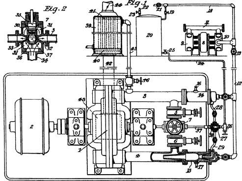
In the first named figure, 1 represents my turbine with its shaft flexibly coupled to a machine performing useful work, as dynamo 2. The general construction of the turbine is preferably as described in my British Patent No. 24,001 of 1910, two nozzles being provided, which are intended to operate in the same direction. The nozzles are contained in two diametrically opposite enlargements of the casing and communicate with inlet pipes 3 and 4 which are joined, through suitable valves 5 and 6, to the main steam admission and control valve 7, shown in section Figure 2 and to be described in detail.
The air compressor can be of any kind but is shown of the reciprocating high speed type, driven by an electric motor 8, and comprising two stages 9 and 10, with an intercooler 11. A pipe 12 carrying valve 13, connects the discharge duct of the compressor to flanged conduits 14 and 15 which are bolted to the inlet pipes 3 and 4 as indicated and equipped with means for ignition, as spark plugs 16 and 17. An extension 18 of pipe 12 leads through a valve 19, to the top of the fuel tank 20 and serves the purpose of maintaining in the latter the required pressure. When the employment of an air reservoir is deemed preferable extension 18 will be put in communication with the same through valve 21. A filling pipe 22, armed with valve 23, is attached to the top of tank 20 while near to its bottom is joined a discharge pipe 24 provided with valve 25 leading through a needle valve 26 to an automatic control valve 27 which is connected by pipes 28 and 29 to the flanged conduits 14 and 15.
The main valve 7 is designed for control of the steam flow both by automatic means and independently of the same. Its construction is clearly indicated in Figure 2, representing a vertical cross-section. The device consists of a casting 30 with inlet ports 31 and outlets 32 and 33, which are joined by flanges to pipes 3 and 4. The open bottom of the casting is connected to a steam inlet pipe 34 while the top carries a throttle valve 35 for turning on and shutting off the steam. Below the seat of this valve the casting has a transversal bore, into which is freely fitted a hollow cylinder 36 with balanced intake and exhaust openings, the latter registering with outlets 32 and 33 in the casting. The cylinder 36 is rigidly joined through a rod 37 with a hollow plunger 38 (Fig. 1) having diametrically opposite ports matching those in the stationary part of valve 27.
The boiler 39, which may be of the vertical tubular type as illustrated, is connected through its headers 40 and 41 on the lower end to main 42 communicating with the exhaust opening 43 of the turbine, and on the upper one to discharge conduit 44 through which the hot fluids, after traversing the boiler tubes, escape into the atmosphere or are led to an economizer for preheating the feed-water or otherwise utilizing the waste heat. A conduit 45 joins the top of the boiler to inlet pipe 3 through a suitable valve 46 which may be operated either by hand or automatically. From the foregoing the operation will now be readily understood. At the start valve 46 being closed and 5 and 6 open, steam from the plant is admitted through throttle and control valve 7 whence it passes into the inlet pipes 3 and 4 and communicating nozzles from which it issues at high velocity setting the rotor in motion, the machine operating purely as a steam turbine. The spark plugs 16 and 17 are then brought into play and valves 13, 19 and 25 opened, the latter allowing the fuel to flow from the tank, chiefly under the action of gravity, to needle valve 26 which is gradually turned on. The fuel thereupon passes through the ports of hollow plunger 38 and pipes 28 and 29 into apparatus for mixing and combustion, the construction of which is clearly shown in the cross-section at the lower branch, it being understood that the arrangement on the upper branch is identical. As will be seen the conduit 15 is armed on one end with a spraying device and on the other with a funnel-shaped extension which is held tight between flanges and projects far into the steam inlet pipe 4. The fuel, atomized by the inrushing air, enters the combustion chamber formed by an enlargement in conduit 15, and is then ignited in the same, the products of combustion escaping into the inlet pipe 4 and mixing with the steam on their way to the nozzle. This kind of apparatus overcomes the difficulty heretofore encountered in attempts to effect combustion practically and will work satisfactorily even if there are considerable fluctuations in the steam and air pressures, as the faster moving fluid aspirates the slower one. It has been assumed that liquid fuel is used but powdered coal may also be employed in substantially the same manner with slight constructive modifications, the powder being conveyed to the combustion chamber either independently of, or with, the air. The quantity of the combustibles is so regulated by manipulation of valves 13 and 26 (and also 5, 6 and throttle 7; if suitable) that the mixture, escaping from the nozzles, will be at a temperature considered safe for the operation of the turbine. To facilitate this any of the well known compound valves may be provided for the purpose of admitting the combustibles always in the required proportions irrespective of their total quantity.
When the steam in boiler 39, raised by the exhaust mixture passing through the tubes, attains the required pressure, it is admitted through valve 46, conduit 3 and corresponding nozzle, to the rotor, adding kinetic energy to the same. Feed-water, preferable heated by the turbine exhaust, is supplied to the boiler in the same measure as steam is drawn off, any ordinary means to this end being employed. The automatic control of the flow of steam and fuel may be effected by any kind of speed governor operatively connected to rod 37 so that the supply is reduced as the speed increases. In addition to the means shown an air valve may be provided, actuated automatically by the governor either through rod 37 or otherwise. For further convenience and to enable the independent control of the air and fuel supply in the two branches, conduits 14, 15 and pipes 28, 29 may be equipped with valves, indicated in Fig. 1, the numbering of which is deemed unnecessary.
The amount of power obtainable from boiler 39 will vary according to conditions. Turbines as described in my said prior specification are capable of operating at a very high exhaust temperature and then the energy recovered from the waste heat in this manner may be a large fraction of the whole useful work. In such as case conduit 3, pipes 14 and 28 together with all their adjuncts, as illustrated can be omitted and the steam supplied directly to the nozzle through valve 46. Or these connections and adjuncts may be left undisturbed and a separate nozzle provided. In admitting the steam from the boiler to the turbine rotor through independent channels, the practical advantage is secured that the pressure may vary considerably without detracting much from the efficiency of the machine, which will be improved through preheating of the combustibles by any of the well-known means.
This plan provides an efficient self-starting mixed-fluid turbine which may also be operated with steam alone, merely by shutting off the air and fuel supply, and is on this account very convenient. Minor departures from it, as may be dictated by the circumstances, will obviously suggest themselves, but if it is carried out on these general lines it will be found highly profitable to the owners of the steam plant while permitting the use of their old installation. However the best economic results in the development of power from steam by my invention will be obtained in plants especially adapted for the purpose. It should be added that this method can also be successfully applied to condensing plants operating with high vacuum. The production and maintenance of the latter will be materially facilitated by the employment of a pump as shown in my British patent before referred to. In such instances, owing to the very great expansion ratio, the exhaust mixture will be at a relatively low temperature and suitable for admission to the condenser. This will call for better fuel and special pumping facilities, but the economic results attained will fully justify the increased outlay.
Having now particularly described and ascertained the nature of my said invention and in what manner the same is to be performed, I declare that what I claim is: -- [Claims not included here]
(25 September 1922)
"Improved Method of and Apparatus for the Economic Transformation of the Energy of Steam by Turbines"
Nikola Tesla
I, Nikola Tesla, do hereby declare the nature of this invention to be as follows: --
This improvement provides a very simple means for increasing the economy of steam turbines and is chiefly intended to be used in the operation of small units but may also be applied, with more or less success, to machines of considerable capacity, the saving effect depending largely on the conditions existing in the steamplants where it is introduced. The economic gain will be especially pronounced in factories and industrial establishments in which the steam pipes are long and serious loss is incurred through condensation and otherwise. The apparatus for carrying out the process is capable of slight modifications and can be employed in conjunction with different types of turbines, but is particularly suited to that described in y British Patent No. 24,001 of 1910, in which propulsion is effected by the adhesive and viscous action of the motive fluid. Irrespective of constructive features the general arrangement will be as follows:
The steam from the boiler is led through a superheater to the turbine nozzle and the high velocity jet projected from it against the rotor creates a suction in the adjacent space which is connected to the superheater pipes or coils, thus causing a strong air current to pass through the same. The air first enters a chamber to which gas or other fuel is supplied and the products of combustion are aspired through the coils into the turbine, superheating the steam to the desired degree, also increasing the temperature of the steam through the turbine rotor and, incidentally, imparting to it some of their kinetic energy. All of these actions cooperate in raising the efficiency of the machine with the result of bringing about an important reduction of operative expense.
To improve the performance of the apparatus I employ two concentric nozzles, steam being admitted to the turbine through one and the products of combustion through the other. Furthermore, in order to turn to good use the waste heat of the exhaust I attach to the latter an economizer for preheating the feedwater and fuel, thereby effecting additional savings.
This invention dispenses with the compressor ordinarily required in connection with a gas turbine and will be found valuable on account of its extreme simplicity, low cost of installment and facilities it affords.
The preferred form of apparatus for carrying out the process above described is illustrated in the accompanying drawings in which:
Figure 1 is a side view in elevation, partly cross-sectioned, and

Figure 2 a vertical section through one of the parts for supplying steam and combustion products to the turbine.

Referring to the figures more specifically, 1 is the rotor and 2,2 the enclosing casing of the turbine which is provided with two diametrically opposite enlargements 3,3 bored out and fitted with concentric conduits 4,4, and 5,5 for supplying the working fluids to the rotor. These are equipped with, or form part of, corresponding discharge nozzles 6,6 and 7,7. The superheater consists of a steam chamber 8 closed at the ends by plates 9 and 10 and containing the coiled pipe 11, the ends of which are led out, one being connected to a combustion chamber 12 and the other to an outlet pipe 13 with branches 14 and 15 leading to the inner supply channel 16, 16. Steam inlet and outlet pipes, respectively, 17 and 18, are provided, the latter with channels 21, 21 of the supply part. Suitable steam, air and gas inlet valves, respectively marked 22, 23 and 24 may be employed for controlling and regulating the supply of the working fluids to the turbine. All the supply channels should be of a section sufficiently large so that the velocities of the fluids through them will be small as compared with those attained in the nozzles.
The operation will now be readily understood. Valves 23 and 24 being closed, the steam admitted by valve 22 passes through inlet pipe 17, chamber 8, outlet 18, branches 19 and 20, spaces 21, 21 and nozzles 6, 6, setting the turbine rotor in motion thus operating the machine as a simple steam turbine subject to the usual limitations in economic performance. The inlet valve 23 is now opened permitting the atmospheric air to be drawn in through coil 11, pipe 13, branches 14 and 15, channels 16, 16 and nozzles 7, 7 to the rotor. Power gas or other fuel is then admitted through valve 24 and upon being ignited in the combustion chamber 12 the products pass through in like manner, assisted by their initial velocity. As a result of this action, coiled pipe 11 is heated to a high temperature and superheats the steam in chamber 8 and also in the supply channels and nozzles, thus adding very materially to the available energy of the steam, at the same time increasing the efficiency of thermodynamic transformation. The products of combustion themselves, impinging against the rotor, contribute usefully some of their kinetic energy. The economic gain effected in this simple manner will be all the more pronounced the poorer the initial quality of the steam and the higher the pressure supply. However, low-pressure steam, as that exhausted from turbines or reciprocating engines, may likewise be economically utilized by this process and means, especially if provision is made for maintaining a vacuum at the exhaust end of the turbine.
The apparatus described is capable of minor modifications. For instance, the combustibles may be admitted to the rotor through the outer channels and steam through the inner ones. Again, the nozzles instead of being coaxial, as shown, may be otherwise constructed and disposed, or single nozzles may be used in their place and the mixture of steam and gases effected before admission to them. However, this can be more or less completely accomplished with coaxial nozzles, as illustrated, merely by shortening one of them. As to the superheater it may be of widely varied design and incorporated with the turbine casing for the purpose of saving energy, weight and space. Departures may also be made in the design of the combustion chamber to suit the fuel employed and the necessary adjuncts for carburetion and ignition will be provided, all of which, being well-known, are omitted from the drawing for the sake of clearness. Obviously, the process can be applied with more or less success in the transformation of the heat energy of elastic fluids other than steam.
This invention provides a self-starting, compact and efficient mixed-fluid turbine and will be found valuable on account of its extreme simplicity, low cost of installment and the facilities it affords.
Having now particularly described and ascertained the nature of my said invention and in what manner the same is to be performed, I declare that what I claim is: -- [ Claims not included here]
British
Patent # 186,799
(12 October 1922)
"Process of and Apparatus for Balancing Rotating Machine Parts"
Nikola Tesla
I, Nikola Tesla, do hereby declare the nature of this invention and in what manner the same is to be performed, to be particularly described and ascertained in and by the following statement: --
In the operation of machinery the accurate balancing of the rotating parts is of great economic importance as vast sums of money are annually expended on account of deficiencies in this respect resulting in loss of power, undue wear and tear, interruption of service and accidents of a more or less serious nature.
Prior to the development of modern high speed apparatus static balancing was depended upon entirely and even now this is frequently the case. The steadily increasing tendency in the direction of high speed brought on the necessity of dynamic balancing and various forms of apparatus for this purpose were devised.
The process I have invented enables this to be done quickly and with a high degree of accuracy and, briefly stated, consists of rotating the body to be balanced, yieldably supported, at a suitable speed and removing excess material from its heavier side by abrasion, until the desired degree of perfection of balance is attained.
As means to this end I may employ a grinding wheel, a sand-blast or jet of other abrasive substance. It might be naturally inferred that the contact of an emery or carborundum wheel with a rapidly whirling machine part would be productive of dangerous shocks and vibrations, and also that grinding at speeds much higher than the usual could now be satisfactorily accomplished. But although these theoretical assumptions appear sound, I have encountered no difficulties of this kind and have performed the operation with the greatest facility and success. This I attribute to the inertia and momentum of the spinning body which makes it insensitive to such asynchronous disturbances as the wheel might produce. However, in certain cases it may be more convenient or preferable to effect the removal of the excess material by a high velocity jet of abrasive material by a high velocity jet of abrasive substance applied tangentially to the part to be balanced. In order to attain the best results it is essential that the latter, when rotated, shall be capable of an appreciable displacement of its center of gravity from the axis of symmetry. This is accomplished by supporting it on a shaft of suitable flexibility, or, if its own shaft is not sufficiently flexible, in bearings yieldably mounted. It is furthermore of great importance, in order to avoid vibrations which would interfere with the proper application of the process, that the speed at which the grinding is effected should bear a definite relation to the critical, corresponding to the fundamental natural vibration, and the following rule should be observed: If the system is run in two bearings the grinding wheel should be an odd multiple or submultiple of the critical. If, on the other hand, the system is supported on one side only, the speed should be an even multiple or submultiple of the critical.
When the structure is revolving at the proper speed I bring the abrasive wheel into operative contact with it at a peripheral or other suitable region and grind off material. As the action continues, the flexure of the shaft diminishes until, finally, its center of symmetry coincides with the center of gravity of the system, or nearly so. This can be noted in many cases by a competent operator without the use of a special device, but suitable visible or audible means may be employed for the purpose.
Preliminary to the application of the process it is advisable to run the part at a very low speed and true it with the wheel. If there exists appreciable flexure of the shaft when the system rests horizontally, the grinding may be done in a vertical position when it is in static balance. A part to be run on a stiff shaft may be mounted on another of suitable flexibility; and as there exist limitations in the accuracy of fitting a cylindrical sleeve, I may employ a tapering one to secure greater precision. However, satisfactory results can generally be obtained in arming the rigid shaft with flexible extensions or holding it in bearings suitable supported. In all cases it is desirable to flood the latter with lubricant of considerable viscosity. When balancing parts to be run at a high temperature they may be inclosed in a casing in which approximately the same temperature is maintained, an opening being provided for the introduction of the abrasive wheel or jet.
My invention will be clearly understood by reference to the accompanying drawings illustrating a form of apparatus I have devised for the quick and convenient balancing of such bodies as rotors of my steam and gas turbines.
Figure 1 shows the general arrangement of the component parts comprising, a casing with an opening on one side, lathe mechanism for feeding the wheel, a tachometer enabling instantaneous readings of the speed to be taken, an instrument for continuous visual indication of the degree of accuracy attained and a preheater of the elastic medium such as compressed air used in the operation;


Figure 2 represents a section through the casing in the plane of a rotor disc, exposing said opening and also the turbine nozzle;
Figure 3 is a view of the essential parts of the balance-indicating instrument and,
Figure 4 illustrates the manner in which a jet of abrasive substance is applied when carrying out my process.
Calling attention specifically to the first names 1 is a casing, enclosing an air- or steam-driven rotor to be balanced, and shown as open at 2 for the purpose of permitting the wheel 3 to be brought into operative contact with the surfaces to be ground. Any suitable drive may be employed but I ordinarily resort to the electric, mounting the wheel directly on the shaft of a motor 4 fixed to a lathe carriage 5 which slides on rails 6, 6 and is provided with means 7 and 8 for feeding the wheel, respectively, along the axis of the motor shaft and at right angles to the same.
As shown in Figure 2 the casing is split horizontally on the centerline in two castings 9 and 10, carefully planed so as to insure their coming into the same position whenever put together, lateral displacement being prevented by dowel-pins 11, 11 (Figure 1) which are driven tight either in casting 9 or 10. These are enlarged and bred out on one side and into the hole is snugly fitted a hollow cylinder 13 with nozzle 14 and intake opening 15 directly connected to the supply line 16 provided with a suitable control valve. The opening at 2 for the entrance of wheel 3 is shown as a simple opening through the casing, but in certain cases I introduce the wheel through an enlargement shown in Figure 2 on the right side, which is often convenient when balancing a rotor in its own casing.
Referring again to Figure 1 the bearings 17 and 18 are also divided horizontally in the plane of the casing joint and their upper and lower parts may be integral with the corresponding casting 9 and 10 for the purpose of saving labor and time. The lower parts of the bearings are equipped with oil supply and discharge pipes 19 and 20.The supply pipe 16 is shown as connected to a coil 21 of a heater 22 which is equipped with a valve for controlling the flow of the heating medium and may be of any known construction. Q worm drive 23 is provided on one end of the rotor shaft for operating the tachometer 24 through a flexible connection. This device may be of any make but I find it advantageous to use the air friction type. On the other end of the shaft is mounted the balance indicator 25 (shown in detail Figure 3) consisting of a member 26 with a pointer 27 on the top and an adjustable mounted weight 28 on the bottom. This member is supported on the outer race 29 of a ball-bearing 30, the inner one 31 being fixed to the shaft, and is thus capable of oscillation. The rotary effort necessary to produce a given deflection of the same being determined by the position of the weight. A graduated scale 32 is attached to the stationary part of the instrument which is placed conveniently for observation by the operator.
Substantially the same apparatus, with the exception of wheel 3, may be employed in connection with the device diagrammatically illustrated in Figure 4,in which a suitable fixture 32 projects a jet 33 of abrasive substance tangentially upon the body 34 to be balanced which is supported on a flexible shaft 35. In this case of course the fixture is mounted on carriage 5 to enable feeding in two directions.
Substantially the same apparatus, with the exception of wheel 3, may be employed in connection with the device diagrammatically illustrated in Figure 4, in which a suitable fixture 32 projects a jet 33 of abrasive substance tangentially upon the body34 to be balanced which is supported on a flexible shaft 35. In this case of course the fixture is mounted on carriage 5 to enable feeding in two directions.
The balancing is done as follows: The rotor being in position for grinding the casting 9 and covers of bearing 17 and 18 are put in place, lubricant forced through pipes 19 and 20 and a motive fluid as compressed air, admitted to nozzle 14, its quantity and temperature being regulated, respectively, by valves on supply pipe 16 and heater 22. The fluid, in traversing the rotor and exhausting through the lower casing imparts motion to the former and brings it up to the desired speed, ascertained by reading of tachometer 24. The abrasive wheel 3 is now fed across the rotor and the indication of the balancing instrument on the graduated scale noted. At the start the deflection of the pointer is likely to be considerable due to the fact that any, however slight vibration of the shaft, increases greatly the pressure on the balls and consequently the torque of the instrument. As the balance improved the deflection diminishes until finally the pointer reaches the zero of the scale indicating that the desired degree of perfection of balance has been attained. As a crucial test the operator may then run the rotor at about the critical speed. This should cause no appreciable vibration or effect on the balance indicator which, instead of carrying a weight, may be equipped with a spring for producing the required pressure on the ball-bearing and opposing the torsion.
When bodies not adapted for rotation in the manner shown are to be balanced, they will be driven independently by belt, electricity or other means, care being taken that no disturbing vibration from them is transmitted to the apparatus. In order to preserve intact the peripheral boundary, if this is essential, I grind the material off from some other place and when desirable, I make a special provision to this end in the design and construction of the part.
I have found my process very valuable in the balancing of high-speed steam and gas turbine rotors but I have used it successfully in a great variety of cases and do not limit its application to any kind of apparatus.
Having now particularly described and ascertained the nature of my said invention and in what manner the same is to be performed, I declare that what I claim is: -- [ Claims not included here]
<< Page 1 : New York Herald Tribune (15 Oct. 1911) ~ "Tesla's New Monarch of Machines" // Scientific American (30 September 1911), p. 290 ~ "From the Complex to the Simple" // Scientific American (30 September 1911), p. 296 ~ "The Rotory Heat Motor Reduced to its Simplest Terms" // E. Stearns: Popular Mechanics Magazine (December 1911) ~ "The Tesla Turbine" // Nikola Tesla: US Patent # 1,061,142 ~ "Fluid Propulsion" // N. Tesla: US Patent # 1,061,206 ~ "Turbine" // N. Tesla: US Patent # 1,329,559 ~ "Valvular Conduit" // Links
Page 3 >> R. Hedin: "The Tesla Turbine" (Construction Plans); Live Steam (Nov. 1984) // Warren Rice: "Tesla Turbomachinery"; Proc. IV International Nikola Tesla Symposium (Sept. 23-25, 1991)