rexresearch.com
rexresearch1.com
Iron Powder Fuel
https://www.youtube.com/watch?v=3JaRJDVJpZk
Iron Powder - The Fuel Of The Future
https://ironfuel.nl/
Iron Fuel - Let's start a new kind of fire
Iron Fuel can solve the industry's problem by storing renewable energy in the iron powder...
https://www.tue.nl/en/news-and-events/news-overview/14-04-2022-500-households-are-warm-thanks-to-rechargeable-iron-powder
500 households are warm thanks to ‘rechargeable’ iron powder
April 14, 2022
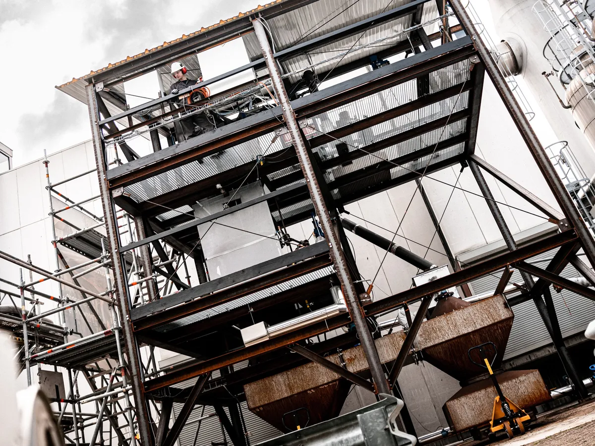
RIFT will work with Ennatuurlijk to set up a test system to power 500 households with iron fuel. The spin-off RIFT (Renewable Iron Fuel Technology) from the TU Eindhoven wants to use iron fuel on a global scale as a sustainable alternative to fossil fuels as a way to lower CO2 emissions. The pilot project that it is running together with Ennatuurlijk is an important step towards achieving this goal. In the Dutch city of Helmond, the start-up is now working on a proof of concept boiler with a capacity of one megawatt. This can be used – via the Ennatuurlijk heat network – to provide heating to five hundred households.
An infinite system
The system works as follows: iron powder is burned in the boiler. A lot of heat is released in this process, for example, for heat networks. What is left over is rust powder. This can be converted into iron powder again by using hydrogen, which in turn ‘charges’ the powder and creates a circular fuel. The start-up is now building a test plant for both of these components. The first test boiler for burning iron powder will be installed in Helmond. The system that converts rust powder back into iron powder is located in Arnhem. This is the first of its kind.
Mark Verhagen, CEO of RIFT, sees iron fuel as an important asset when it comes to sustainability. “Industrial processes and heat networks need vast amounts of energy. Sustainable alternatives such as electricity and hydrogen are not always able to provide this. Our networks are not designed to supply so much energy to industry on top of the current usage within such a short period of time,” he states. “So in these sectors, alternatives like iron powder are really important.”
No CO2 and less nitrogen
“No CO2 is released in this process. In addition, nitrogen emissions during the process are much lower than those from coal or gas,” Verhagen explains. Iron fuel also offers a number of advantages. For one thing, it has a high energy density. One cubic metre of iron fuel contains as much energy as eleven cubic meters of hydrogen under high pressure. It is also much safer to store and transport than hydrogen. Finally, it does not lose any energy while in storage. “That does happen with batteries, for example; they run down over time.”
Philip de Goey, professor of combustion technology, was at the forefront of groundbreaking research into so-called metal fuels. He calls the collaboration between RIFT and Ennatuurlijk a very important step that will demonstrate the validity of this solution. "Iron fuel is one of the most promising solutions for the energy transition because it is easy and safe to transport and can be stored in large quantities. In recent years, I have worked with several industrial consortia to put this into practice and with success."
Student team
Start-up RIFT sprang from the SOLID student team at Eindhoven University of Technology (TU/e). The team has been working with researchers at the university on the technology behind the iron fuel ever since 2015. The student team tested the technology – as part of the Metal Power Consortium – in 2020 at the factory of Swinkels family-run brewery. Iron fuel produced the heat that was needed in the brewing process. Mark Verhagen was SOLID’s team leader in the 2019/2020 academic year. “That’s when we were able to demonstrate that the technology does work. With the current pilot, we can prove that it also has commercial potential.”
The technology was tested in 2020 at the factory of family brewery Swinkels.
Verhagen stresses that student teams are important drivers for new technologies such as iron fuel. “In a student team, the right kind of people get together. People who really believe in a particular innovation and want to put their shoulders to the grindstone to actually push it to the next level,” he says impassionedly. “At SOLID, we often received skeptical reactions from people who thought this technology wouldn’t work. But it does work!”
Collaboration
Now, as CEO of RIFT, he takes a very different view of the people who are contributing to innovation. “We work with a very diverse team made up of fourteen people. The younger ones know all about this new technology and the over-50s have a huge wealth of experience that they are keen to share with others. That way, we make sure we get the best results together.” Partners who are facilitating the first pilots are also invaluable to the company, he notes. “They are sticking their necks out in order to really bring this new technology to the market. That makes them important trailblazers when it comes to the energy transition.”
Scaling up
In two years, RIFT wants to build a five-megawatt iron fuel power plant. To that end, a letter of intent has already been signed for a collaboration with Veolia Industrial Services. “With the current one-megawatt pilot, we are studying the most important components of the plant in a commercial environment. After that, we can further optimize the system and scale it up to the five-megawatt system.”
Verhagen: “I see iron fuel as an important sustainable alternative to fossil fuels alongside wind turbines, solar panels and hydrogen. Our goal is to be able to decarbonize heavy industry around the world with iron fuel.”
https://www.ironfueltechnology.com/
Iron Fuel Technology
https://www.ironfueltechnology.com/wp-content/uploads/2024/03/Whitepaper-Iron-Fuel-Technology-Jan-2024.pdf
Whitepaper -- Iron Fuel Technology
[ PDF ]
https://spectrum.ieee.org/iron-fuel
Iron
Fuel Shows Its Mettle
The plentiful metal could be a carbon-free fuel and store energy long term
Prachi Patel
The plentiful metal could be a carbon-free fuel and store energy long term
Prachi Patel
By the end of June, a large 1-megawatt plant that burns iron fuel will fire up, producing the heat needed to brew beer at the Swinkels brewery near Eindhoven, Netherlands, in a test lasting for several months. Startup IRON+ is a joint venture between three companies and built on technology first demonstrated as a 100-kilowatt system in 2020 by the Metal Power Consortium, which includes the Eindhoven University of Technology and innovation center Metalot, which was spun out of the university. ..
By the end of June, a large 1-megawatt plant that burns iron fuel will fire up, producing the heat needed to brew beer at the Swinkels brewery near Eindhoven, Netherlands, in a test lasting for several months. Startup IRON+ is a joint venture between three companies and built on technology first demonstrated as a 100-kilowatt system in 2020 by the Metal Power Consortium, which includes the Eindhoven University of Technology and innovation center Metalot, which was spun out of the university.
Iron is one of the most abundant metals on Earth, and the most produced. It has an energy density of about 11.3 kilowatt-hours per liter—better than gasoline. Burning iron powder produces heat that can be used directly or converted into electricity by a steam turbine, leaving behind iron oxide, or rust. This can later be reduced—that is, the oxygen can be stripped away—back into iron powder. “You can think of iron fuel as a clean, recyclable coal,” says Bergthorson.
Hydrogen is already a carbon-free green fuel if produced by splitting water using renewable electricity. But it is also an ultralight, voluminous gas, so it must be converted using high pressures and extreme cold into liquid, which then has to be stored and transported in special containers. Iron, by contrast, is already moved in dry containers for a lower cost.
So while both hydrogen and metals are essentially a way to store energy, using metals makes more sense, Bergthorson says. Technical assessments by Metalot and the Technical University of Darmstadt suggest that “it’s more efficient to produce iron from hydrogen gas than to produce liquid hydrogen. So iron powder as fuel is more expensive than gaseous hydrogen but cheaper to produce and move across the oceans than liquid hydrogen.”
That’s not to say iron fuel doesn’t come with its own challenges. It does not ignite as easily as hydrocarbon fuels, and the flame speed is slower, which makes it unstable and more prone to extinguishing. Altiro gets around this problem by adding a little natural gas to ignite the iron powder when the boiler first starts up. They have also come up with a technology to stabilize the flame so that it burns for long periods of time without extinguishing, Bergthorson says.
Collecting the resulting iron oxide is also tricky. Altiro’s technology ensures the formation of iron oxide particles that are large enough to easily capture “using cyclones and other methods without needing high-tech or costly equipment,” Bergthorson says.
Some of the iron powder inevitably evaporates to form iron-oxide nanoparticles that cannot be collected and turned back to iron. Both Altira and IRON+ have worked out ways to minimize this nanoparticle formation to reduce metal loss. “We improved the boiler by increasing the efficiency of heat transfer,” says Philip de Goey, a mechanical engineering professor at Eindhoven and cofounder of Metalot. “The evaporation of iron powder leading to nanoparticle emissions has been decreased by a factor of 10, so it is smaller than 0.3 percent. The nanoparticles are not emitted in the atmosphere but captured in a HEPA filter.”
a photograph of a gloved hand holding black powder that is also slipping through the fingers into a barrel filled with more powderRIFT generates heat through the combustion of iron powder.Krols MediThe next step for iron fuel is further increasing the conversion efficiency of iron to iron oxide since some of the iron does not get completely converted, de Goey says. Then there are market hurdles to jump, such as increasing iron powder production and lowering the cost of producing green hydrogen.
If these problems can be overcome, you could use renewable electricity to produce iron, store it as long as necessary, transport it there and then burn it for power when needed, says Bergthorson. “Places that have excess energy could make iron, and others can buy it. This way, you could commodify renewable energy so it can be globally distributed without the need for transmission lines. Metals can solve a big problem in the renewable energy transition: long-duration energy storage.
https://teamsolid.org/
Team Solid
Enabling circular energy -- A revolutionary method of storing hydrogen in a circular and compact manner
IRHYS
The practice of Iron-Based Hydrogen Storage uses iron in a circular process that consists of two steps:
REDUCTION
Iron oxide can be reduced to iron using hydrogen, in this way storing the energy of hydrogen in iron. The iron can be stored and transported in a cheap and safe way without energy losses.
OXIDATION
When hydrogen is needed, the iron is oxidized into iron oxide using steam, releasing hydrogen in the process. The hydrogen released can be applied in various applications such as import and export or in the off-the-grid high heat industry. The circular use of iron as an energy carrier makes the storage of hydrogen more compact, safe, and cheap.
IRON-BASED HYDROGEN STORAGE
Breakthrough technologies are needed to really tackle the challenge of large scale energy storage. The solution of iron-based hydrogen storage is one such technology.
This solution offers an alternative option to store hydrogen in a safe way. In the so-called steam iron process, steam is reacting with iron to start oxidation. In this process hydrogen and rust are produced. Afterwards, the hydrogen can be filtered from the remaining steam and used for multiple purposes.
The rust that is also produced in the steam iron process can be regenerated by means of carbothermal reduction, sustainable electrothermal reduction or by adding green hydrogen again. In this way, hydrogen can be stored in a circular system.
IRON COMBUSTION
Another technique involves a circular principle in which iron powder is used as a medium for energy storage, also called iron fuel. Iron fuel can be burned to form iron oxide, better known as rust. In this process, a large amount of thermal energy is released that can be used in industrial processes. The resulting iron oxide is a solid material, so it can be captured after the combustion process. It is then reused by regenerating it with green hydrogen into new iron fuel. This way, iron fuel offers a revolutionary method to store energy in a circular and carbon-free fashion.
A detrimental side of iron fuel that it has a relatively low specific energy density, which is the amount of energy per kilogram of iron. Therefore, it cannot be used in applications in which weight is of importance such as cars, trucks and planes. Also, it can only be transported in an economic manner by ship or train. However, most of the heavy industries are located on railways or waterways. Therefore, iron fuel is applicable to those industries.
A
burner and a process for combusting metal powder
NL2032415
NL2032415
IRON POWDER AS RECYCLABLE FUEL, AND ASSOCIATED SYSTEMS AND METHODS
WO2023194903
The present invention relates to an iron fuel boiler process for iron fuel combustion, comprising the steps of combusting an iron fuel suspension medium comprising iron fuel and oxygen in an iron fuel burner arrangement to obtain an iron oxide containing medium; receiving the iron oxide containing medium into an iron fuel boiler arrangement for transferring the iron oxide containing medium towards a separation unit disposed at the end of said iron fuel boiler arrangement; exchanging heat between the iron oxide containing medium and a boiler of the iron fuel boiler arrangement with a heat-exchange medium during the transfer of the iron oxide containing medium through said iron fuel boiler arrangement; and separating iron oxide from the oxide containing medium to obtain solid iron oxide particles and a gas flow. The process further comprising the step of cooling said iron oxide containing medium with a cooling medium during said transfer of the iron oxide containing medium through the iron fuel boiler arrangement such that a temperature of the iron oxide is achieved of below the sintering temperature of the particles at said separation unit.
A burner process for iron fuel combustion, comprising the steps of: providing an iron fuel suspension medium comprising iron fuel and oxygen in a suspension solid density of between 2 to 15 kg/Nm3 and more preferably of between 4 to 8 kg/Nm3; introducing said iron fuel suspension medium into an iron fuel burner arrangement at a velocity of between 5.5 and 55 m/s and more preferably between 20 and 40 m/s; introducing air from air inlet means into said iron fuel burner arrangement, wherein said air from said air inlet means is introduced with an overall angular momentum ratio between said air and said iron fuel suspension medium of between 3 and 12 and more preferably between 3.8 and 8.9; mixing said iron fuel suspension medium by subjecting it with said air such that an overall oxygen-to-fuel equivalence ratio is obtained between 1.0 and 2.5 and more preferably between 1.2 and 1.8 for obtaining a combustible medium in the said burner arrangement; igniting said combustible medium to provide a combusting iron fuel containing medium.
Technical field
The present invention relates to a burner process for iron fuel combustion.
Background of the invention
Energy is indispensable. The amount of energy consumed worldwide has increased enormously over the last decades. Although the amount of energy originating from renewable energy sources such as wind and solar has increased over the last decades and especially over the last years, a large part of the energy still originates from fossil fuels.
With the use of fossil fuels also comes the highly undesirable carbon dioxide, CO2, emission. And in order to achieve climate objectives, the total CO2 emission should be reduced significantly. To this end, carbon-neutral fuel, and even more carbon-free fuel, is a preferable source of energy and promising resource to fulfill worldwide energy requirements but still meet the climate objectives. Carbon- neutral fuel is considered fuel does not release more carbon into the atmosphere than it removes, whereas carbon-free fuel produces no net-greenhouse gas emissions or carbon footprint at all. Typically, with carbon-neutral fuel, CO2 or other greenhouse gasses are used as feedstock.
Heat intensive industries are responsible for a large part of the total CC>2-emissions. But for many industries there are currently few or no fossil fuel alternatives available that on the one hand are scalable, and on the other hand able to provide sufficient energy with a high degree of certainty and consistency, yet are completely CC>2-emission-free with low NOx-emissions. Solar energy and wind energy can partly meet this need. However, due to the fact that they are intermittent, they are often not, or insufficiently suitable to replace fossil fuels and to meet the demand for energy from these industries at all times.
In recent years, a lot of research has therefore been carried out into a feasible alternative that is fully CC>2-emission-free. Iron fuel has the potential to meet that need and to become the candidate of choice.
Iron fuel is a very promising fuel in which energy is stored in the iron powder when and where needed. In the right conditions, iron powder is flammable and has the property that when the iron powder is burned, a lot of energy is released in the form of heat, without CC>2-emissions and lower NOx-emission than alternative fuels. This heat can then be converted into hot water, steam or electricity for use in any kind of application or industry. Another important property of iron powder is that only rust remains during combustion, while no CO2 is released during the combustion of the iron powder. The rust, as a product, can be collected and converted back into the iron powder in a sustainable manner, which makes it a fully circular process.
The fact that the iron fuel is CO2 free, circular and easy, safe, and cheap to store and transport makes it an ideal clean and sustainable alternative for fossil fuels to meet the demand for energy in various industries but also in all kinds of other applications.
Although the use of iron fuel may already be a proven clean and sustainable alternative to fossil fuels, there are also several challenges. One of the challenges is to maximize heat release without reducing the quality of the obtained rust, since the rust is to be converted into iron fuel again. There is therefore a need to improve known burner processes suitable for iron fuel combustion in a way in which the energy generated is optimized, whereas the burner process is controlled in a way which is optimal for collecting the rust as a waist product, such that it can be easily collected and converted back into the iron powder in a sustainable manner, which makes it a fully circular process. It is an object of the present invention to provide an improved burner process for iron fuel combustion.
It is a further object of the present invention to provide an improved burner process for iron fuel combustion with effective and efficient energy generation from the burner process, and wherein the rust can be collected for converting it back into iron powder in an improved and sustainable manner, whereas the contamination of the burner process is kept at a minimum.
Summary
In a first aspect, the invention relates to a burner process for iron fuel combustion, comprising the steps of:
(a) providing an iron fuel suspension medium comprising iron fuel and oxygen in a suspension solid density of between 2 to 15 kg/Nm<3>and more preferably of between 4 to 8 kg/Nm<3>;
(b) introducing said iron fuel suspension medium into an iron fuel burner arrangement at a velocity of between 5.5 and 55 m/s and more preferably between 20 and 40 m/s;
(c) introducing air from air inlet means into said iron fuel burner arrangement, wherein said air from said air inlet means is introduced with an overall angular momentum ratio between said air and said iron fuel suspension medium of between 3 and 12 and more preferably between 3.8 and 8.9;
(d) mixing said iron fuel suspension medium by subjecting it with said air such that an overall oxygen-to-fuel equivalence ratio is obtained between 1.0 and 2.5 and more preferably between 1.2 and 1.8 for obtaining a combustible medium in the said burner arrangement;
(e) igniting said combustible medium to provide a combusting iron fuel containing medium.
The present disclosure relates to a burner process for iron fuel combustion. The inventors have found that the known burner processes which are suitable for example for burning coal, coal-like material, waste and biomass are not suitable or less suitable for burning iron fuels. For burning iron fuel, specific process design requirements are applicable which are different from these known burner processes.
Burning iron fuel has different chemical and physical properties when compared to conventional fuels. Another difference is that iron fuel is intended to be used as a burnable clean energy medium in which the iron powder can be used in a circular manner, meaning that the waste product of the iron fuel after burning, i.e. the rust or iron oxide powder, is to be collected and should be suitable to be converted back into iron powder. As mentioned, the properties of iron fuel are very different from other fuel types like diesel, coal or coal-like materials. As such, the parameters for traditional burning processes do not suffice and are not able to meet the requirements for such burner process in terms of i) fuel supply, ii) stable, continuous combustion, iii) general performance of iron fuel combustion arrangements and iv) for the purpose of reusing residual iron oxide powder.
Iron powder has many advantages, amongst which, that it is cheap, abundant, easy to transport and has a high energy density. Moreover, the storage and transport have little requirements, whereas other high energy density fuels such as hydrogen for example require extreme compression and/or cooling for efficient transport and storage. Iron fuel also has little tendency to lose energy during long periods of storage.
One of the challenges of using iron powder as a sustainable and circular energy carrier lies within the burning process, as known burner processes are simply not suitable for iron fuel application and/or are not efficient.
Recovering rust for converting it back into iron power is not the only requirement for an iron burning process to be considered successful, as the iron to iron oxide conversion should be maximized as well in order for the process to be considered sufficiently efficient. What the inventors found was that these requirements could be met with a burner process in which the oxygen-to-fuel ratio, especially at specific locations in the burner arrangement is controlled. Upon introduction into a burner arrangement, the iron fuel should be in suspension, i.e. the iron is to be provided as an iron fuel suspension medium comprising iron fuel, i.e. iron powder and oxygen (preferably in a medium containing oxygen and possibly other gasses) in a solid density of between 2 and 15 kg/Nm<3>and more preferably between 4 to 8 kg/Nm<3>. The iron fuel suspension medium is preferably transported as a uniform distribution throughout the crosssection of the pipe or duct, meaning the suspension is homogeneously transported. The skilled person will acknowledges that a fully uniform distribution of the iron fuel powder is ideal, but that in practice it will deviate from this to a limited extent due to, among other things, the pathway of the medium towards/into the burner arrangement.
According to the present disclosure uniform distribution or homogeneous transport is to be interpreted as one or multiple homogeneous distributions of the iron fuel (particles) within the suspension medium. For example the uniform distribution with respect to particle sizes present in the iron fuel particle size distribution, and most preferably, homogeneous distribution in respect of both the particle mass and the particle size within the medium.
Upon introduction of the suspension medium into the burner arrangement, it is subjected with a specific impulse that enhances the dispersion of the powder in the widening burner geometry and enables for proper mixing of the suspension medium with the additional air from the air inlet means. The air inlet means thus provide a further supply of air into the burner arrangement, in addition to the air already comprised in the suspension medium prior to the introduction of the suspension medium into the burner arrangement which serves the purpose of providing oxygen for combustion.
The air inlet means introduce air into the burner arrangement in which the air mixes with the suspension medium. The burner arrangement may comprise of one or a plurality of air inlet means which may be disposed in parallel, in series, or in any other applicable configuration. This lowers the solid density of the suspension medium towards the required oxygen-to-fuel equivalence ratio. After mixing and obtaining the aforementioned ratio, preferably in a homogeneously distributed manner throughout the burner, the medium is suitable for combustion which is defined as combustible medium, such that in the final step of the process the combustible medium can be ignited and a stable and efficient burning process is obtained.
In view of the present description ignition is to be understood as either self-ignition of the medium in the right conditions, e.g. oxygen-to-fuel ratio, iron fuel solid density, mixture temperature, velocity, etc., but ignition may also be understood as an active step of direct ignition of the medium through ignition means or indirect igniting as for example pre-heating means to increase the temperature of the medium to such a degree that it ignites. Also, ignition may be interpreted as both pre-heating and actively igniting the medium through ignition means.
By mixing the suspension medium with an oxygen containing gas to increase the oxygen level in the medium to the aforementioned ratio the iron particles concentration is lowered throughout the cross-section of the burner and the suspension density is thus lowered. However, mixing the suspension medium with too much oxygen would increase the oxygen levels to such a degree that the iron fuel could burn too fast and/or at too high temperatures, resulting in peak temperatures, which in turn create undesirable nanoparticles which are difficult to separate and difficult to convert back into iron fuel, and further creates emission problems due to unrecoverable particles. To achieve a desired oxygen-to-fuel ratio and suspension density, the medium is subjected to air from the air inlet means according to a specific angular momentum ratio between 3 and 12 and more preferably between 3.8 and 8.9. The overall angular momentum ratio is of more importance and is high, and higher when compared to conventional burner processes, amongst others due to the density and heating value of the iron fuel, resulting in the density and required velocity of the suspension medium. This results in sufficient degree of mixing and the defined oxygen-to-fuel fuel ratio. The inventors found that subjecting the suspension medium to a high impulse could result in particle slagging, agglomeration and attrition which has a negative effect on the burner process and on the separation (and further conversion into iron fuel) of the rust particles and results in mass losses due to sticking to the burner wall surface which is undesirable as it has a negative effect operability of the burner and on the amount of iron oxide mass can be reused reuse of iron oxide. If the impulse would be too low, i.e. a lower angular momentum than defined above, it would result in non-optimal mixing which has a negative effect on flame stability, completeness of combustion and formation of nanoparticles in thermal hotspots. Compared to conventional burners, in which the flame stability is mainly defined by the geometry, the burning process of iron fuel requires more than just a specific geometry, amongst other due to the density of the suspension medium, the velocity of the suspension medium and the massflow of the particles.
As way of example of the above mentioned, a 1 MW burner may have an iron fuel flow of approximately 500 kg/h. When using a suspension density of 6 kg/Nm3 and a suspension velocity of 40 m/s, this requires a suspension inlet with a diameter of approximately 27.2 mm. The area-weighted mean radius of this inlet is 9.62 mm in this case. Given an air introduction using 6 air inlets, in 2 consecutive steps of 3 equally sized inlets at velocity of 40 m/s with an air-to-fuel equivalence ratio of 1.2, this gives an air inlet diameter of 35.8 mm. When keeping a constant axial velocity in the burner arrangement, the cross-sectional diameter of the burner arrangement in the first and second inlet stage then equals 67.7 and 91.8 mm respectively. The radial distance from the center of the suspension flow to the mean of the center of the air inlets then equals approximately 39.9 mm. Given the angles a and 0 both equal 90° the angular momentum of the suspension flow and air flow then equal 6.52E-2 and 4.98E-1 kg*m<A>2/s respectively, this leads to an overall angular momentum ratio of approximately 7.64. It is expressed that this example is merely one example of a burner process according to the present disclosure, and other variations to the disclosed embodiments can be understood and effected by those skilled in the art in practicing the claimed invention.
In an example, the temperature of at least part of the combustible medium obtained in step (e) has a minimum temperature equal to the ignition temperature of the iron fuel. The flame stability, not only at or shortly after the ignition, but also for a longer period of time, is obtained when the combustible medium has a temperature equal to the ignition temperature of the iron fuel.
In an example, the temperature of the iron fuel suspension medium in step (b) is at least approximately equal to the ambient air temperature of the burner arrangement and more preferably has a temperature of between ambient air temperature of the burner arrangement and maximum temperature lower than the ignition temperature of the iron fuel. With ambient air temperature also the outside temperature is meant.
In an example, the upon step (c) and (d) the process further comprises heating with heating means, for heating said at least part of said combustible medium to a temperature of at least the ignition temperature of the iron fuel.
In an example, said air of said air inlet means are providing at a temperature of between 0 and 400 °C.
In an example, said air of said air inlet means are providing at a temperature which is at least approximately equal to the ambient air temperature of the burner arrangement and more preferably between ambient air temperature of the burner arrangement and 400 °C.
To improve the combustion and create a stable controllable flame, the iron fuel suspension medium may be introduced at increased temperature, e.g. by heating the suspension medium in but more preferably prior to the introduction thereof in the burner, or by heating the air of the air inlet means, preferably prior to introduction into the burner. To realise this one or more may be provided of: heating means, recirculation of hot fume gasses, heating within external heat of other external processes, or indirect heating from the fume gasses through heat-exchanging means. The temperature in the burner may also be increased by heating through heating means, recirculation, a pilot flame, hot spiral or one of several types of electrical heating means. In an example, said air inlet means are arranged for directing said air from said air inlet means in a tangential manner, and/or at an angle, with respect to said iron fuel suspension medium, into said iron fuel burner arrangement.
In an example, a swirl of iron fuel suspension medium is created.
In an example, said air inlet means are arranged for directing said air from said air inlet means in a coaxial manner, with respect to said iron fuel suspension medium, into said iron fuel burner arrangement.
In an example, the iron fuel suspension medium has a homogeneous distribution of iron fuel particles in said medium.
In an example, the iron fuel particles in said iron fuel suspension medium are homogeneous with respect to their particles sizes.
The impulse is achieved by introduction of air through the air inlet means. These direct the air either tangentially, at an angle or coaxially with respect to the inlet of the suspension medium. These inlet ports of the air inlet means may be positioned tangentially in the circumference wall of the burner arrangement and may have 2, 3, 4, 5 or more air inlet ports. The air inlet ports of the air inlet means may be positioned in a tangential or coaxial manner in such a configuration that the (mixed) suspension medium starts to swirl, which improves the mixing and the homogeneity of the iron fuel in the medium. Moreover, is has a further effect of keeping the medium away from walls of the burner arrangement such that adherence or deposition of particles on wall surface of the burner arrangement is prevented or at least minimized and more iron oxide can be reused for iron fuel production.
In an example, said iron fuel suspension medium has an oxygen concentration of 6-22 vol.%.
In an example, said air from said air inlets has an oxygen concentration of 6-22 vol.%. With an oxygen concentration of about 6-22 vol. % the air from the air inlet means add to a stable and efficient burning process and the concentration may be applicable to the suspension medium upon introduction into the burner arrangement, but also to the air of the air inlet means.
In an example, said iron fuel burner arrangement has a widening geometry for promoting said spreading the flow radially outward of said iron fuel suspension medium with said air from said air inlet means.
In an example, said iron fuel suspension medium is introduced into said iron fuel burner arrangement at an angle and/or with a swirl.
As mentioned above burning iron fuel may have a tendency to clogging of the burner arrangement and corresponding parts of the iron fuel burning system. When the suspension medium achieves a swirl pattern, it not only improves burning properties and mixing of air, but may also prevent or reduce deposition on the walls of the burner arrangement when the swirl is not too strong. To further benefit from these effects the suspension medium can be introduced into the burner arrangement in such a manner to increase this swirl effect by introducing it at an angle or as swirl.
The invention will now be described in more detail by means of specific embodiments, with reference to the enclosed drawings, wherein equal or like parts and/or components are designated by the same reference numerals. The invention is in no manner whatsoever limited to the embodiments disclosed herein.
Brief description of the Drawings
Fig. 1 shows in an illustrative manner the steps of the process of burning iron fuel according to an aspect of the present disclosure.
Fig. 2 shows a schematic overview of the medium flows considered in the calculation of the overall angular momentum ratio.
Detailed Description
In Fig. 1 the four basic and minimal steps are shown in an illustrative manner of a burner process of iron fuel combustion. Combustion - or burning - of iron fuel is different from the combustion of conventional fuels. Known burning processes suitable for example burning coal, coal-like material, biomass and waste, are not suitable or less suitable for burning iron fuels. Burning iron fuel requires specific process design concepts which are different from these known burner processes. Due to the different chemical and physical properties of iron fuel as compared to conventional fuels, the conventional burner processes do not suffice.
Iron, just like some other metals, can be burned to generate heat. The iron powder used for such purpose has a particular and preferred particle size or grain size which may lie in the range between 1 and 250 micrometer, and more preferably, between 20 and 150 micrometer.
To convert iron fuel into heat, the iron fuel is burned in oxygen containing gas, such as air. Preferably, the heat may further be used in a boiler or other means to transport the heat to desired locations, or to convert it into rotational energy, e.g. to generate electricity.
The combustion of iron fuel is a highly specific process and requires other measures than those of known burner processes of conventional fuels, especially since flame stability is challenging. Moreover, the recovery of the iron oxide or rust to such a degree that it is suitable for regenerating it back into iron powder which again can be used as iron fuel is also challenging. A burner process which meets these requirements, and which thus allows efficient recovery of the rust while having efficient heat transfer is considered even more challenging.
In Fig. 1 a burner process for iron fuel combustion is shown which meets these requirements and overcomes such challenges. The burner process comprises of several steps and at least the following: In a first step, A, the iron fuel suspension medium is provided. The medium may comprise several components but at least comprises iron fuel (iron powder) and oxygen, possibly in a medium completely comprised of oxygen but more likely, containing oxygen and other components. The iron fuel and oxygen are provided in a suspension solid density of between 2 and 15 kg/Nm<3>and preferably between 4 and 8 kg/Nm<3>.
The iron fuel suspension medium with such properties is introduced, in the next step B, into the iron fuel burner arrangement. The speed at which the suspension medium is introduced is at least above 5.5 m/s to assure the particles remain suspended in the airflow, and does not exceed 55 m/s as that would introduce further difficulties in respect of flame stability and especially mixing of the air by the air inlet means.
The iron fuel suspension medium does not yet meet the requirements which are considered sufficient for combustion of the fuel. Therefore, the suspension medium is subjected to an air flow at step C. The flow is provided by air inlet means which may comprise of one means, or several means and may have one or several (preferably evenly distributed) air inlet ports which introduce the air into the burner arrangement. The air flow mixes with the iron fuel suspension medium to obtain a medium which meets combustion requirements and as such is defined as a combustible medium. The mixing is the result of the air inlet means to introduce the air and direct the air to the suspension medium with a certain impulse creating an angular momentum in the flow. The dimensionless overall angular momentum ratio Gratia) between the air and suspension medium flow is calculated using
Image available on "Original document"
where
Ixis the respective angular momentum defined by I = p • v<2>• A • r. It must be noted that the angular momentum is defined as the momentum of the impulse G defined by G = p • v<2>• A. The latter being equal to the momentum flux J of an inlet multiplied with its surface area. The momentum flux J is defined by J = p • V 2.
• pairis the air density at the said inlet in kg/m<3>.
• Psus-p '<s>
Image available on "Original document"
suspension density in kg/m<3>at the said suspension inlet, not including the mass flow of the air in the suspension mixture.
• vairis the velocity of the air inlet(s) in m/s.
•<v>susp is the velocity of the suspension inlet in m/s.
• Aairis the surface area of the said air inlet(s) in m<2>.
•<A>susp is the surface area of the suspension inlet in m<2>.
•<r>susp is<area>weighted mean radius of suspension flow in meter (assuming uniform distribution for the cross-section of the flow)
• rairis the radial distance from the center of the suspension flow in meter (or centre of the flow) to the mean of the centre of the air inlets (but does not exclude non-mean) and
• a and 6 are the angles between the suspension flow and air inlet means as schematically depicted by Fig. 2.
The burner process according to the present disclosure having a dimensionless overall angular momentum ratio lratio) between the air and suspension medium flow may also be defined by
The impulse [kg * m *s<A>-1] may be defined by
G = m * V
G = p * v * A
The angular momentum [kg * m<A>2 * *s<A>-1] may be defined by
I = G * R I = m * V * r
I = p * y<2>* A * r
And the momentum flux by j = p * y<2>
The overall angular momentum ratio is between 3 and 12 to ensure the suspension moves sufficiently radially outward (creates angle in Fig. 2), but also such that the radially outward movement of the suspension flow does not become too large such that extreme wear of burner components occurs. Preferably this ratio is between 3.8 and 8.9. The upper limit poses a risk of wear of particles and potential agglomeration and formation of stalagmites I stalactites in the burner arrangement and downstream components.
Once the suspension medium is mixed, and the combustible medium is obtained, the medium may be ignited. In this way heat is generated, with an iron oxide containing medium as residue, from which the iron oxide can be separated, recovered and regenerated back into iron fuel.
The following data represents several cases of the suspension and air conditions as experimental data for the present invention and disclosed embodiments. In the example and the cases thereof, it is demonstrated that at least for case 5 a lambda value A or air-fuel ratio, is achieved which is in the preferred ratio of 1.2 and 1.8. Cases 4 and 5 also demonstrate a lambda value by which the claimed effect is achieved, although slightly beyond the preferred ratio bandwidth...
The present invention relates to a method for producing iron fuel from metal oxide containing charge materials via reducing the metal oxide containing charge materials. An object of the present invention is to produce iron in a specific powder form having a particle size distribution and specific surface area, wherein the iron powder is to be used as a starting material for iron fuel combustion.
The present invention relates to a method for producing iron fuel from metal oxide containing charge materials via reducing the metal oxide containing charge materials.
Iron ore reduction with hydrogen mixtures as the reducing agent is industrially proven and is well known as such. Examples of industrial implementation relate to direct reduction processes. The input material in these processes is predominantly iron ore, which has a broad range of different properties in terms of particle size, morphology and composition. Moreover, these processes are designed for (usually liquid) steelmaking, which poses relatively unstrict requirements on particle morphology after reduction and which contains a carburization step to add carbon to the iron. In such steelmaking processes iron oxide and hydrogen are transported to the reactor, where the iron oxide is reduced to iron. The produced iron leaves the reactor and is subsequently transported and stored. Solids that are present in the outlet gas are separated in a gas-solid separation operation and returned to the reactor. The outlet gas is subjected to a gas separation operation for the removal of water vapor produced during the reaction. Unused hydrogen in the reactor outlet gas is recycled to the inlet of the reactor. These steelmaking processes are not based on the use of iron as a fuel source.
US 4,082,545 relates to a process for the direct reduction of iron ore, comprising establishing a plurality of fluidized beds, heating and progressively reducing iron ore by passing the iron ore in series through the plurality of fluidized beds, fluidizing the beds with reducing gas by passing the reducing gas up through the bed, removing partially spent reducing gas from each the bed, cooling and washing the partially spent reducing gas to remove substantially all the solids there from, heating the washed gas, and again feeding the heated fluidizing gas through the bed.
US 2016/348199 relates to a method for reducing metal oxide containing charge materials, comprising: reducing the metal oxide containing charge materials by a reduction gas in at least a first and a second fluidized bed units, and flowing the reduction gas through the fluidized bed units counter currently to the metal oxide containing charge materials, removing as off-gas from the first fluidized bed unit the reduction gas used during reduction of the metal oxide containing charge materials in the at least two fluidized bed units, compressing at least some of the off-gas in at least one recycle gas compressor to produce hot recycle gas, and then cooling the hot recycle gas in at least one aftercooler to produce cold recycle gas, at least partially removing CO2 from the cold recycle gas to produce product gas, admixing the product gas with the reduction gas, optionally after pre-heating in a heating device, conveying the metal oxide containing charge materials by a propellant gas from at least one delivery tank by a pipe line into the first fluidized bed unit.
US 3,288,590 relates to a method of continuously reducing an iron oxide in particulate solids form with a reducing gas largely hydrogen under dilute phase suspension conditions which comprises grinding the iron oxide to all pass 100 mesh and have an average particle size of about 200 mesh, heating the reducing gas to a temperature in the range of 480 to . under a pressure of 11 - 35 atm, passing the gas upwardly through a substantially vertical reaction zone, at a velocity in the range of 1 .5 to 7.6 m/s, preheating the iron oxide to at least about 480 degr C, continuously feeding the finely divided preheated iron oxide to the rising column of reducing gas at a rate to maintain an average solids density in the range of 80-240 kg of metallic oxide per cubic meter of gas under the conditions in the rising column, and separately removing from the effluent of the reaction zone, a substantially solids-free gas and the reduced iron fines, wherein the reaction zone consist of a series of vertical chambers forming stages interconnected to accomplish a downflow of gases from the top of one stage interconnected to the upflow in the next stage.
US 4,420,332 relates to a process for concurrently carrying out production of reduced iron and thermal cracking of a heavy oil which comprises the steps of introducing a fine iron ore and a heavy oil into a fluidized-bed thermal cracking reactor to effect thermal cracking of the heavy oil at a temperature in the range of 500 DEG to 600 DEG C. into products of thermal cracking and carbonaceous by-product material. The fine iron ore is in the form of particles having an average diameter of about 10-30 micrometre and the fine iron ore with deposits of the carbonaceous material is introduced into a first fluidized-bed reducing furnace and contacted with a reducing gas at high temperature blown thereinto in a fluidized state to reduce the fine iron ore into reduced iron at a temperature in the range from 800 DEG to 1000 DEG C. and to form an exhaust gas. The cracked gas, light oil and residual oil is separated by distillation from the products of thermal in a fractionation system, and a part of the reduced iron is transferred to a gas reformer wherein a fluidized-bed of the transferred reduced iron is formed in the gas reformer and the cracked gas or the residual oil is reformed by contact with the fluidized reduced iron in the gas reformer into a reducing gas mainly composed of hydrogen and carbon monoxide. WO 00/01856 relates to a method for reducing iron-oxide-containing particles to metallic-iron-containing particles in a reducing zone of a moving bed reduction reactor with a reducing gas mainly composed of hydrogen and/or carbon monoxide, the method comprising introducing the iron-oxide-containing particles into the reducing zone at a first level to form a moving bed of particles in the lower portion of the reducing zone and extending down into a discharge zone of the reactor, injecting below the first level the reducing gas into the moving bed to define there above a moving bed reducing sub-zone, withdrawing from the reactor the overflow of the metallic-iron-containing particle fines from the top of the fluidized bed, withdrawing the reduced metallic-iron-containing particles from the nonfluidized moving bed in the discharge zone, and withdrawing the spent reducing/fluidizing gas from above the fluidized bed in the reduction zone.
US 3,303,017 relates to a process of reducing iron: ore by direct reduction in a fluid bed, consisting of introducing the fluidizing gas into the fluid bed through multiple conical gas distributors, each of which is fed by a separate cyclone gas-solids separator, wherein the fluid bed comprises at least two conical gas distributors, each fed by a separate cyclone gas-solids separator, wherein the cyclones are located internally and directly feed gas to the conical gas distributors.
A disadvantage of the present processes for producing iron fuel from metal oxide containing charge materials via reducing the metal oxide containing charge materials is that these processes are unable to produce iron in a specific powder form to be used for the purpose of iron fuel combustion. One of the negative issues here is that particle agglomeration takes place in the process. Another negative one is that the produced material is pyrophoric. Both particle agglomeration and the formation of pyrophoric material form a barrier for the use of iron in a specific powder form as a starting material in iron fuel combustion.
The term “Pyrophoricity” is to be understood as a property of a material. In more detail, a material is qualified as pyrophoric if it ignites spontaneously in air at or below 54 °C or within 5 minutes after coming into contact with air. It is caused by the high specific surface area of the material, yielding an extremely low ignition temperature for oxidation. When the ignition temperature is low enough, auto-ignition at atmospheric conditions can take place. Pyrophoricity of iron particles after reduction has been reported to be a serious issue in fluidized bed reduction, where a high surface area of the material is obtained. The tendency to reoxidation depends on the reduction temperature. Studies have shown that the surface area of fine metal powders generally decreases with reduction temperature.
The term “agglomeration or sticking” is to be understood as a property of a material as well. Sticking of particles is regarded as the most serious problem encountered in reduction of iron oxide. It is especially problematic in fluidized bed reduction because it results in de-fluidization of the particle bed. And when particle bed de-fluidizes the reduction process of iron oxide cannot be continued. The factors affecting the sticking problem are for example temperature, metallization ratio, gas flow rate, the reducing atmosphere and particle properties. Generally, sticking is observed above a critical temperature and only occurs after the emerging of metallic iron. The latter is often ascribed to the formation of iron whiskers at higher metallization ratio which increases the sticking tendency of particles. An example of a method to prevent sticking includes the application of a low reduction temperature. Agglomeration will lead to loss of product quality since the product does not meet the desired requirements with regard to particle size.
An object of the present invention is to produce iron in a specific powder form having a particle size distribution and specific surface area, wherein the iron powder is to be used as a starting material for iron fuel combustion.
The present invention thus relates to a method for producing iron fuel from metal oxide containing charge materials via reducing the metal oxide containing charge materials according to the wording of claim 1 .
The present inventors found that by applying specific process design features the agglomeration and pyrophoricity of particles can be limited. The iron powder thus produced is to be used as a starting material for iron fuel combustion.
The conditions in the fluidized bed are such that the bed is typically a bubbling fluidized bed. In a bubbling fluidized bed the gas rate is above the minimum fluidization rate. In a situation of minimum fluidization rate, at some location the force exerted upwards on every particle equals the particle weight, and the particle is suspended and the gas rate is called minimum fluidization rate. Any extra increase in rate creates bubbles of gas that quickly flow upward within the system, i.e. known as a bubbling fluidized bed. Increasing the superficial gas velocities will result in a transition from bubbling into the turbulent fluidized bed regime.
The combustion of iron yields various distinct types of iron oxide: hematite (Fe2Os) and magnetite (FesC ). These materials can be reduced by electricity and/or gaseous reducing agents including syngas, carbon monoxide, methane or hydrogen. The chemical processes taking place during the reduction of iron oxides by hydrogen are described by the equilibrium reactions:
Fe2O3(s) + 3 H2(g) 2 Fe(s) + 3 H2O(g)
Fe304(s) + 4 H2(g) 3 Fe(s) + 4 H2O(g)
FeO(s) + H2(g) Fe(s) + H2O(g)
As the iron (oxide) does not reach a molten state in the process, it is also referred to as direct reduction. The chemical reactions show that the process involves reactions between solid and gaseous reactants. An important difference between reduction with hydrogen and with carbon monoxide, which is traditionally used for steel production in blast furnaces, is that reduction with hydrogen is endothermic. This means that energy must be added to the system to guarantee a constant reduction temperature. According to the present invention the addition of energy to the system can be done by preheating the input material or integrating a form of heating in the system design. According to the present invention a fluidized bed reactor is used for the purpose of contacting the gases and solids. The present system operates at a specific process conditions which will be discussed later here.
According to the present method the stream containing iron fuel is transported to a vessel. It is clear that such a vessel is to be understood as a construction wherein two or more vessels are present, for example a system consisting of vessels placed in parallel. The same situation applies for the fluidized bed unit. It is clear that several fluidized bed units may be placed in parallel or in series and the present method is by no means restricted to a specific number of fluidized bed units.
In an example, the step of removing partially spent reduction gas from the fluidized bed unit further comprises a step of separating coarse solids from the partially spent reduction gas and returning these coarse solids to the fluidized bed unit.
In an example, the method for producing iron fuel further comprises separating fine solids from the partially spent reduction gas after the step of separating the coarse solids. In an example, the method for producing iron fuel further comprises a step of removing water from the partially spent reduction gas before returning the partially spent reduction gas to the fluidized bed unit.
In an example, the method for producing iron fuel further comprises a step of removing water from the mixture of partially spent reduction gas and fresh reduction gas before returning the mixture to the fluidized bed unit.
In an example, the aforementioned steps of removing water can be both applied in the method for producing iron fuel.
In an example, the water is removed from the partially spent reduction gas via one or more processes chosen from the group of condensation, adsorption, absorption and membrane filtering, or a combination thereof.
In an example, the method for producing iron fuel further comprises pre-heating and/or drying the metal oxide containing charge materials before feeding the materials into the fluidized bed unit, wherein the pre-heating temperature is preferably in a range of 40 and 1000 °C.
In an example, the step of feeding the metal oxide containing charge materials to the fluidized bed unit further includes a step of pressurizing the metal oxide containing charge materials to the pressure prevailing in the fluidized bed unit.
In an example, the method for producing iron fuel further comprises a step of heat exchange between the partially spent reduction gas from the fluidized bed unit and the mixture of partially spent reduction gas and fresh reduction gas and, the heat exchange takes place before returning the mixture of partially spent reduction gas and fresh reduction gas to the fluidized bed unit.
In an example, the method for producing iron fuel further comprises pre-heating the mixture of partially spent reduction gas and fresh reduction gas before returning the mixture of partially spent reduction gas and fresh reduction gas to the fluidized bed unit.
The fluidized bed unit is preferably operated under the conditions of a pressure of at least s atm and at most 13 atm, more preferably at least 4 and at most 12 atm, a temperature of at least 400 and at most 800 °C, more preferably at least 400 and at most 700 °C, and a reduction gas velocity in the fluidized bed unit of at least 5 and at most 200 cm/s, more preferably at least 10 and at most 150 cm/s. The temperature of the reactor may be controlled by an external heating source.
In another example the method comprises the following steps: feeding metal oxide containing charge materials to a fluidized bed unit, reducing the metal oxide containing charge materials by flowing a reduction gas through the fluidized bed unit, wherein the fluidized bed unit is operated under the conditions of a pressure in a range of 1 and 15 atm, a temperature in a range of 300 and 1000 °C and a reduction gas velocity in the fluidized bed unit in a range of 0,9 cm/s and 270 cm/s, removing partially spent reduction gas from the fluidized bed unit, admixing the partially spent reduction gas with fresh reduction gas and returning the mixture of partially spent reduction gas and fresh reduction gas to the fluidized bed unit, removing a stream containing iron fuel from the fluidized bed unit, wherein the step of removing the stream containing iron fuel from the fluidized bed unit comprises the following sub-steps: transporting the stream containing iron fuel to a vessel, reducing the pressure of the vessel to ambient pressure, cooling the stream containing iron fuel.
In an example the stream containing iron fuel while under pressure is cooled to a temperature below the point where agglomeration of the iron fuel occurs.
In an example the step of transporting the stream containing iron fuel and the step of cooling the stream containing iron fuel while under pressure takes place simultaneously. The metal oxide containing charge materials consist of oxides of iron and unavoidable impurities, such as metals, for example nickel, manganese, copper, lead and cobalt, carbon and sulphates, or mixtures thereof.
In an example, the fluidized bed unit comprises a plurality of fluidized bed units placed in series.
In an example, the fresh reduction gas comprises hydrogen in an amount of at least 50 vol.%.
The iron fuel removed from the fluidized bed has a Sauter mean particle size of at least 10, preferably at least 20 pm, and at most 200 pm, preferably at most 150 pm.
The metal oxide containing charge materials have a Sauter mean particle size of at least 10, preferably at least 20 pm, and at most 300 pm, preferably at most 200 pm. The drawings schematically illustrate an example of a method according to the invention according to the invention. The present method is not restricted to the specific example disclosed here.
Figure 1 is an example of the method for producing iron fuel.
Figure 2 is another example of the method for producing iron fuel.
Figure 3 is another example of the method for producing iron fuel.
The metal oxide containing charge materials 10, preferably oxides of iron, nickel, manganese, copper, lead or cobalt or mixtures thereof, are at least partially reduced or more specifically reduced by reduction gas 28 which flows through a fluidized bed unit 11 of metal oxide containing charge materials 10. Metal oxide containing charge materials 10 may undergo a pretreatment, consisting of a storage 1 and transport of metal oxide containing charge materials, i.e. iron oxide, preheating unit 3, lock hopper in 5, solids preheating 7 and solids feeding 9. The metal oxide containing charge materials originating from storage 1 are transported to an optional pre-heating unit 3. In case the charge materials are heated, a heated stream 4 is sent to lock hopper in 5. The function of lock hopper in 5 is to introduce the metal oxide particles in a pressurized environment to allow introduction of the solids into fluidized bed unit 11 at elevated pressure. An additional function of lock hopper in 5 is to prevent agglomeration of the starting materials via fluidization thereof. In addition, the function of lock hopper in 5 is to purge out any gaseous oxygen present in and in between metal oxide particles to ensure that substantially no oxygen enters fluidized bed unit 11 . In an embodiment feed 6 originating from lock hopper in 5 is sent to an optional preheating unit 7. After such a treatment feed 8 is sent to a solids feeding unit 9. The function of unit 9 is to dose and feed the metal oxide particles 10 into fluidized bed unit 11. Preheating unit 7 may be incorporated in unit 9. In fluidized bed unit 11 the metal oxide particles are contacted with the reducing agent, i.e. a hydrogen-containing gas thereby converting metal oxide particles into metal particles. Fluidized bed unit 11 may also include a heating unit 30 for controlling the reaction temperature. Coarse particles from the gas stream exiting the particle bed present in fluidized bed unit 11 are separated from the gas flow and the coarse particles thus separated are returned into the particle bed present in fluidized bed unit 11. Gas flow 12 exiting fluidized bed unit 11 is sent to heat exchanger 14. In heat exchanger 14 the energy of gas flow 12 is exchanged with hydrogen gas flow 27. The function heat exchanger 14 is thus cooling gas flow 12 that is discharged from the coarse particle separation while pre-heating hydrogen gas flow 27 that will eventually enter fluidized bed unit 11 thereby increasing the energy efficiency of the total system. Gas flow 15 coming from heat exchanger 15 is sent to separator unit 16. The function of separator unit 16 is to separate and to discharge fine particles from gas flow 15 exiting heat exchanger 14. Fine particles 17 are discharged and stored. A make-up hydrogen gas flow 20 is combined with gas flow 21. Hydrogen gas flow 19 may be compressed in compressor 18 resulting in hydrogen gas flow 20. The combined hydrogen gas flow, i.e. hydrogen gas flow 20 and hydrogen gas flow 21 , may contain water and other impurities, and water and other impurities are removed in water removal unit 22 and the resulting flow 24 is discharged. The function of water removal unit 22 is not only cooling gas flow 21 to effectuate condensation of water vapor from gas flow 21 but to separate and discharge the condensed water from the gas stream which is recycled. Gas flow 26 originating from water removal unit 22 is sent to compressor 25 and gas flow 27 thus compressed is routed to heat exchanger 14. The function of compressor 25 is to pressurize recycle gas to overcome any pressure drop across the system and to create gas velocity in fluidized bed unit 11 . The heated gas flow 28 is sent to fluidized bed unit 11. Product stream 29 coming from fluidized bed unit 11 is sent to lock hopper unit 31. Lock hopper unit 31 has out has multiple functionalities, i.e. to cool down particles containing product stream 29 with an inert gas in order to prevent sticking/agglomeration of the particles and to prevent oxidation of the particles when exposed to ambient air. Agglomeration will lead to loss of product quality, since the product does not meet the desired requirements with regard to particle size. Contact with ambient air will lead to a loss of product quality as well. In addition, lock hopper unit 31 may also be provided with an inert gas flow for fluidizing the iron particles to prevent sticking in the lock hopper system itself while cooling. Furthermore, in lock hopper unit 31 the pressure of the iron particles stream 29 is brought from system pressure back to atmospheric pressure. Product stream 29 may also contain hydrogen gas and remaining parts of hydrogen and water are flushed. The removal of hydrogen from product stream 29 ensures that no reaction takes place outside fluidized bed unit 11 and allows for safe operation of downstream operations. The iron particles containing stream 32 is stored in iron fuel storage 33. It is to be noted that dry particles 32 ensure a safe storage, without the risk of iron particles being oxidized by water or clogging as a result of water condensation in storage containers 33.
The process scheme according to Figure 2 is similar to the one shown in Figure 1 , except for the situation around fluidized bed unit 11. Metal oxide particles 10 are fed into fluidized bed unit 11 and mixed stream 35 of coarse particles and hydrogen is sent to separator 13. In separator 12 a stream 38 of coarse particles is recycled into fluidized bed unit 11. Gas flow 12 comprising hydrogen and fine particles coming from fluidized bed unit 11 is sent to heat exchanger 14. In heat exchanger 14 the energy of gas flow 12 is exchanged with hydrogen gas flow 27. The function heat exchanger 14 is thus cooling gas flow 12 that is discharged from the coarse particle separation while pre-heating hydrogen gas flow 27 that will eventually enter fluidized bed unit 11 thereby increasing the energy efficiency of the total system. The heated gas flow 28 is sent to fluidized bed unit 11 and may be further heated by heater 30, resulting in hydrogen gas flow 34. All remainder process units and streams are similar to the ones discussed above in connection with Figure 1.
The process scheme according to Figure 3 is similar to the one shown in Figure 2, except for the situation at the outlet of fluidized bed unit 11 . Product stream 29 coming from fluidized bed unit 11 is sent to unit 39 for cooling down the particles containing product stream 29, preferably with an inert gas in order to prevent sticking/agglomeration of the particles and to prevent oxidation of the particles when exposed to ambient air. Agglomeration will lead to loss of product quality since the product does not meet the desired requirements with regard to particle size. Contact with ambient air will lead to a loss of product quality as well. The stream 40 thus cooled is sent to lock hopper unit 31 and unit 31 may also be provided with an inert gas flow for fluidizing the iron particles to prevent sticking in the lock hopper system itself while cooling. Furthermore, in lock hopper unit 31 the pressure of the iron particles stream 40 is brought from system pressure back to atmospheric pressure. The iron particles containing stream 32 is stored in iron fuel storage 33. It is to be noted that dry particles 32 ensure a safe storage, without the risk of iron particles being oxidized by water or clogging as a result of water condensation in storage containers 33.