Manuel
António GOMES
Pyreheliophorus
Pyreheliophorus
https://www.youtube.com/watch?v=uumqRoORPC0
FREE ELECTRICITY - FREE PURE WATER - FREE RECYCLED METAL - Invention lost in history
dutchsinse
https://en.wikipedia.org/wiki/Pyreliophorus
Pyreliophorus
The Pyreliophorus was a device similar to a burning glass, created by the Portuguese priest Manuel António Gomes, also known as padre Himalaya, whose objective was to melt many different types of materials using solar energy.[1] The device used several reflecting mirrors to concentrate the sunlight into a common point. With this device, it was possible to reach a temperature of around 3500 °C, enough to melt many types of metals and rocks.[2] Unlike a common burning glass, the Pyreliophorus uses a concentric parabolic array of mirrors to concentrate the sun light into a common point, instead of a lens. The device uses a clock system that makes the mirror array concentric axis to rotate.
This device was one of the main attractions on the Saint Louis World's Fair in 1904, and it was awarded with two gold medals and with one silver medal. Himalaya protected his Pyreliophorus using the patent system in many jurisdictions, including the British one on the patent application number GB190116181 or in the American with the patent application US797891.
https://cdm17210.contentdm.oclc.org/digital/collection/lpe/id/422
Father Himalaya's Pyrheliophor
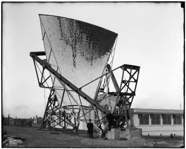
Exhibitions--Missouri--Saint Louis--1900-1910
Description The Pyrheliophor was erected at the Louisiana Purchase Exposition -- the 1904 St. Louis World's Fair -- by Manual Antonio Gomes, a Portuguese priest known as Father Himalaya. The experimental apparatus, ""suggesting a giant spider ... was constructed to ascertain the amount of heat that might be secured by the concentration of rays of the sun. It contained 6,117 mirrors so placed as to reflect the sun's rays upon a single point. By this means a heat of more than 7,000 degrees Fahrenheit was secured ... The Pyrheliophor ... stood upon the high ground southwest of the Palace of Forestry, Fish and Game."
https://en.wikipedia.org/wiki/Manuel_Ant%C3%B3nio_Gomes
Father Himalaya, c. 1906
.jpg)
Manuel António Gomes (9 December 1868 – 21 December 1933)
was a Portuguese Catholic priest, inventor and physicist. He
was a very tall man, and was nicknamed Father Himalaya (in
Portuguese: Padre Himalaya), a name he proudly used
frequently. He was born at Santiago de Cendufe, Arcos de
Valdevez in 1868 and died at Viana do Castelo in 1933.
Father Himalaya was a pioneer in Portugal of solar energy and other uses of renewable energy. He was a vegetarian and was interested in naturopathy, particularly fitotherapy and hydrotherapy. He studied in Paris with Marcellin Berthelot and developed mathematical and astronomical theories to construct innovative ways of concentrating solar radiation in order to maximise useful energy production. Gomes is the creator of the pyreliophorus, a series of reflecting mirrors to concentrate sunlight towards a common point in order to melt materials.
He lived in the United States and Argentina between 1927 and 1932. In Argentina he wrote a book about cosmology, his inventions and his innovative views on several areas of science.
Pyreliophorus
The pyreliophorus is a device similar to a burning glass. It was invented by the Portuguese priest Manuel António Gomes (1868-1933), also known as Padre Himalaya, who wanted to create a device capable of melting many different materials using solar energy. He succeeded, since his pyreliophorus could make the temperature reach roughly 3500 degrees C, sufficient to melt many different metals and rocks.
The pyreliophorus recieved a lot of attention at the Louisiana Purchase Exposition (the St. Louis World’s Fair) of 1904, where it was awarded with two gold medals and one silver medal.
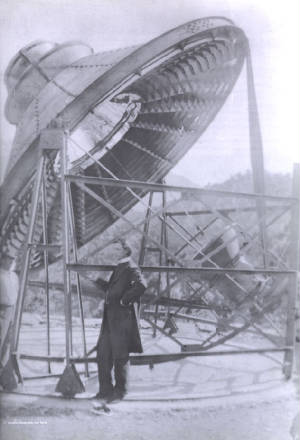
Pyreliophorus Construction
A pyreliophorus contains several reflecting mirrors which are used to concentrate the sunlight to one single point.
Unlike a traditional burning glass, the pyreliophorus have a concentric parabolic array of mirrors instead of a lens. A clock system makes the mirror array rotate along the sun alignment.
Gomes patented his invention in several jurisdictions, including Great Britain and the USA.
About the inventor
Manuel António Gomes was born on the 9th of December, 1868, in Santiago de Cendufe, along the northern frontier of Portugal and Galicia (Spain).
Gomes was a Catholic priest, and since he was also a very tall person, he got the nickname Padre Himalaya (Father Himalaya). He was very fond of this nickname and used it frequently.
Gomes was educated in France, where he studied under the famous chemist Pierre Bertheot and learned about how solar radiation could be concentrated. In addition to being a priest, Gomes was a physicist and inventor, and he became a trailblazer in the field of solar energy and other forms of renewable energy in Portugal. Gomes also had a strong interest in fitotherapy, hydrotherapy and other forms o f naturopathy.
While living in the USA and Argentina in 1927-1932, Gomes wrote a book about cosmology and his inventions.
Gomes died in Viana do Castelo in northern Portugal on the 21st of December, 1933.
Construction
A pyreliophorus contains several reflecting mirros which are used to concentrate the sunlight to one single point.
Unlike a traditional burning glass, the pyreliophorus have a concentric parabolic array of mirrors instead of a lens. A clock system makes the mirror array rotate along the sun alignment.
Gomes patented his invention in several jurisdictions, including Great Britain and the USA.
About the inventor
Manuel António Gomes was born on the 9th of December, 1868, in Santiago de Cendufe, along the northern frontier of Portugal and Galicia (Spain).
Gomes was a Catholic priest, and since he was also a very tall person, he got the nickname Padre Himalaya (Father Himalaya). He was very fond of this nickname and used it frequently.
Gomes was educated in France, where he studied under the famous chemist Pierre Bertheot and learned about how solar radiation could be concentrated. In addition to being a priest, Gomes was a physicist and inventor, and he became a trailblazer in the field of solar energy and other forms of renewable energy in Portugal. Gomes also had a strong interest in fitotherapy, hydrotherapy and other forms of naturopathy.
While living in the USA and Argentina in 1927-1932, Gomes wrote a book about cosmology and his inventions.
Gomes died in Viana do Castelo in northern Portugal on the 21st of December, 1933.
US797891 -- SOLAR APPARATUS FOR PRODUCING HIGH TEMPERATURES
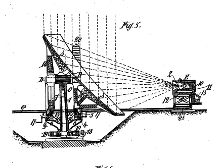
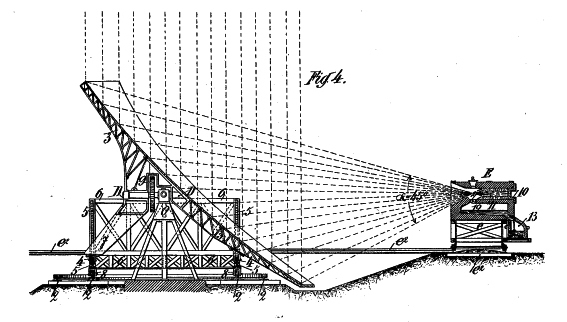
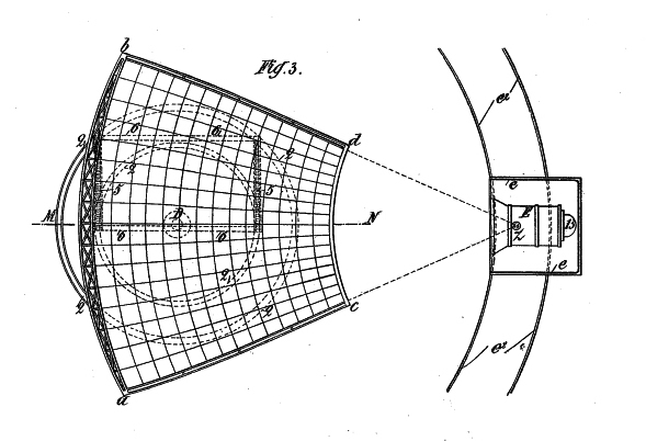
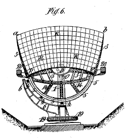
GB190116181 -- Improved Apparatus for Making Industrial Use of the Heat of the Sun and Obtaining High Temperatures.
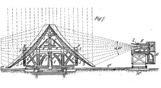
Reflectors -- Apparatus for making industrial use of the heat of the sun and obtaining high temperatures such as are required in chemical and metallurgical arts. The apparatus comprises a reflector derived from a paraboloidal or like surface, mounted to move about two or three axes and to bring the sun's rays to a focus within a furnace, crucible, water-heater or steam boiler, or a chamber for the production of nitrous acid. The reflector is made up of plane or curved silvered glass or metal elements, which may be of trapezoidal, circular, or other form, and which, when congregated, form a sector derived from the frustum of a paraboloid of revolution. Eight sectors may be mounted together, with movements about a horizontal and a vertical axis, or one sector alone may be employed, as in the apparatus shown in Fig. 4 for directing the rays within a crucible E. In this apparatus, the reflector is moved about the horizontal axis D by the gearing of pinions 4 with the vertical curved racks 5, and is moved about the vertical axis o by means of the rollers 8 and rails 2. A suitable framework for the reflector and a counterbalance are provided. The truck e carrying the crucible e, may be wheeled upon a track concentric with the vertical axis 0, and this form of supporting arrangement is arranged with two reflectors to give two diametrically-opposite heating foci, as shown in Fig. 7. An oblique axis of motion may be added to the movements of the reflector, and with two motions only the horizontal axis may be arranged parallel to the chord or tangent of the normal arc of the reflecting surface.
Improved Apparatus for Making Industrial Use of the Heat of the Sun and Obtaining High Temperatures.
COMPLETE SPECIFICATION.
Improved Apparatus for Making Industrial Use of the Heat of the Sun and Obtaining High Temperatures.
The apparatus comprises a reflecting surface arranged to cause the solar rays to converge upon a confined focus placed in the centre of a furnace, crucible or other receiver, this furnace or other receptacle being if desired placed completely outside the reflecting system; it comprises besides means for adjusting or setting the apparatus so as to maintain the convergence of the rays upon the focus selected whatever be the height of the sun above the horizon ; it comprises also a kind of furnace or heat receiver specially constructed for the purpose of making industrial use of the solar heat according to my invention.
I now proceed to describe my arrangement, reference being made to the accompanying drawings, upon which:-
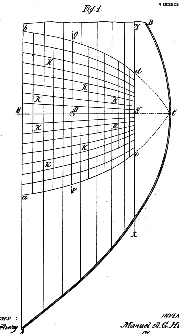
Figure 1 is a section through the axis of a paraboloid of revolution A B C of which the part near the vertex is cut along X Y perpendicularly to the axis and in which a truncated sector a bed forming an essential part of the apparatus is cut out.
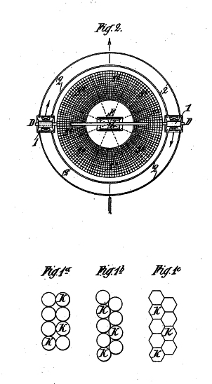
Figure2 shows in plan and upon a reduced scale the same truncated paraboloid A B X Y of Figure 1, divided into eight sectors S1 to S8 mounted upon a horizontal axis D D arranged perpendicularly to the axis of the paraboloid of revolution at the level of the focus Z and supported by means of two columns 1, 1 movable upon the circular track 2.
Figure 3 shows in plan and in the working position the truncated paraboloidal sector a bed of Figures 1 and 2, directing the solar rays within a crucible E, the sun being vertical.
Figure 4 is a vertical section upon line M-N of Figure 3.
Figure 5 is a modified form of the arrangement shewn in Figure 4.
Figure 6 is a front view of the reflecting system of Figure 5 and in section upon line P---fZ of Figure 1.
Figure 7 shows, in part vertical section two reflecting systems placed back to back in such a manner as to form two foci in two furnaces symmetrically opposite.
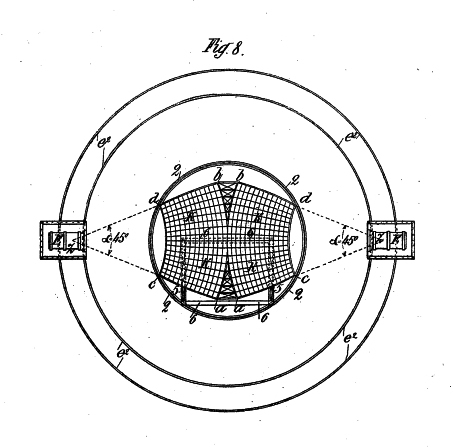
Figure 8 is a plan view on a reduced scale of Figure 7. Figures 9 to 13 relate to modifications in the construction of and means for manipulating the reflecting surface.
The essential feature of the invention consists in the use of a reflecting surface formed by a sector of a paraboloid of revolution a b, c d (Figure 1) capable of reflecting a conical pencil of solar rays a b Z (Figures 2 to 13) having an angle at the vertex sufficiently acute for the focus Z to be formed at the centre of the furnace or other receiver E and to produce a very high temperature.
In point of fact the paraboloid of revolution and similar surfaces, although being the ideal form of optical apparatus for concentrating the solar rays upon a physically perfect focus, cannot form a focus capable of Industrial use, because the rays reflected reaching the focus from all sides of the figure, cannot be concentrated upon the centre of a furnace or receiver for heating; they can heat only around and outside a crucible or a boiler. ~ In this manner, the temperatures developed are relatively small and the losses of heat through radiation and reflection are very important.
My invention is based upon the principle of the resolving of the paraboloid of revolution into as many parts as may be necessary for obtaining a portion of a paraboloid capable of producing a focus practically and easily useable in metallurgy and in all branches of industry.
This result is attained by cutting at the vertex a paraboloid of revolution upon line X Y (Figure 1) and by dividing the paraboloidal frustrum so obtained into, for example eight parts or sectors S' to S8 (Figure 2) and by suitable adjusting or setting one of these sectors as will be hereafter seen.
The aperture of this paraboloidal sector a bed (which for greater simplicity I term the "reflector", Figures 1,2 and 3, is prefer ably about 45 degrees but may be larger or smaller according to circumstances. This sector may be cut off at one or more sides or upon all sides in such case assuming the form of either a frustrum of a paraboloidal sector which is that shown upon the drawings or a circle, an ellipse, a polygon or other shape. This reflector may be formed of one or more parts or elements of a paraboloid the shape of which may be varied, that is to say each of the elements forming the reflector may have the shape of a trapezoid K which is that illustrated in Figures 1 to 13, or that of a circle (Figures 1 and lb) or a hexagon (Figure 1 ) a triangle, a square &c.
In case the reflector is composed of a number of small elementary reflectors which will in fact be the usual case, the section and the surface of each of them may be plane or curved, spherical, parabolic, polyhedral, etc according to the dimensions of the apparatus.
These small elementary reflectors k k (Figures 1,2 and 3) forming the reflector are arranged in regular manner upon a support or framework 3,3 (Figures 3 to 13) so that each pencil of solar rays reflected by each one of the small elementary reflectors is directed towards the same igneous zone or focus Z (Figures 2 to 13) in which the temperature is proportionately higher as the surface of the reflector is greater and the area of the igneous zone or focus Z is more confined. The general shape of this framework 3,3 upon which are placed the small elementary reflectors k k (Figures 1,2 and 3) is that of a section or sector of a paraboloid of revolution (Figures 1 to 13) or of a paraboloidal polygon, an ellipsoid, an hyperboloid, or the like.
The elementary reflectors 10 10 (Figures 1,2 and 3) are made of silvered glass, polished metals or any other suitable reflecting' material and they are mounted either fixedly, or movably upon the framework 3,3 (Figures 4 to 13) according to whether or not it is wished to vary the focal length.
The whole combination forming the reflector is usually provided' with two adjustments so as to maintain the convergence of the rays at the focus Z.
Such adjustments for setting the apparatus are shown in Figures 4 to 11.
The first motion is that of rotation around a horizontal axis D; the second is a rotation around a vertical axis 0. These two movements, suitably controlled and combined ensure the convergence of the rays at the focus Z whatever be the altitude of the sun, according to the hour of day and the time .of year in all latitudes.
From the constructional point of view, the direction of these movements relatively to the axis of the sun or solar pencil and to the radius of the earth at the point in question, varies according to the different methods of carrying out the invention and, consequently, the position of the axes D and 0, especially D, can be equally varied.
Further, as will be presently seen, more than two movements may be imparted to the reflector a b c d. As a general rule whatever be the method dof setting the apparatus, the mean inclination of the reflector to the sun is preferably 45 degrees, but it may be greater or less according to circumstances. '
By way of example, I will describe some arrangements by means of which the reflector can be adjusted in various ways.
To explain the differences between and the object of these various arrangements, I now refer to Figure 2 of the drawings showing the frustrum of a paraboloid of revolution mounted upon a horizontal axis D passing through the focus Z perpendicularly to the axis of i evolution and supported by 'two vertical columns or frames 1, 1 movable upon the circular rails 2 placed centrally around the apparatus.
By causing this paraboloidal frustrum to revolve about the horizontal axis D and this latter to travel upon the track 2 around the centre, so that the axis of the solar pencil remains a prolongation of the axis of the paraboloid, it will be seen that each of the sectors S1 to S8 produces a cone of reflected rays having different movements and, consequently, foci in Z, capable of always being located at the centre of a furnace E or any other suitable device affording a concavity.
The arrangement shown in Figure 3 having these two movements of rotation each cone of rays reflected by each of the sectorsS1 .to S8 must also have two movements of rotation.
But since the axis D passes through the focus Z perpendicularly to the axis of rotation, the cone of rays reflected by the two sectors S1 and S2 revolves because its, axis is the same as the axis D. The focus produced by these sectors S1 and S2 thus remains in the prolongation of the always horizontal axis whatever be the position of the sun, having when the sun is oblique, scarcely a movement of rotation which remains parallel to the horizon.
The arrangement of reflector shown in plan, Figure 3, and in vertical section
Figures 4 and 5, corresponds with the frustrum of the paraboloidal sector S1 of Figure 2 and as in that case produces a focus Z which always remains in the prolongation of the horizontal axis D D1, having like it a single movement of translation upon the track 2 central about the vertical axis 0 which renders this applicable by preference to metallurgy and the chemical arts which necessitate the use of high temperatures and heavy and awkward furnaces, crucibles or other apparatus.
As will be seen from Figures 2 and 4, the horizontal axis D always maintains its relative position; it is inclined about 45 degrees to the normal at the centre of the reflector a bed and the focus Z is in the plane and on a prolongation of this same axis D describing each day when the sun is oblique, scarcely an arc of a circle upon the track 2 from the centre formed by the vertical axis 0 The movement of rotation of the reflector (t, b c d around the horizontal axis D is guided or obtained (Figure 4) by means of pinions 4,4 travelling upon two racks 5,5 arranged as the arcs of a circle struck from the horizontal axis D.
These two racks 5,5 (Figure 4) rest upon a suitable framework 6 movable upon the track 2 arranged centrally around the vertical pivot 0.
A portion 7 of the framework serves as a counterbalance maintaining the equilibrium of the apparatus.
The rotatory movement of the reflecting surface around the vertical axis 0 is effected by means of rollers 8 upon the rails 2. This movement takes place only when the axis of the solar pencil is oblique relatively to the radius of the earth.
When the axis of the solar pencil is in line with the earth's radius, i.e., vertical, only a movement of rotation around its horizontal axis D is imparted to it and the focus Z remains fixed during the whole or the day.
The two adjustments of this apparatus as ,also that of the truck e carrying the crucible E are obtained by means of suitable gear-wheels or the like, the arrangement of which may be varied according to the motive power, whether human, animal or mechanical. These gear wheels arc suitably connected with the wheel 9 and rollers 4 and 8 or with other parts of the apparatus.
The minerals or other materials to be melted or treated in the furnace E are inserted preferably through a door or an opening 10 in such a manner as to form a tubular wall or casing, resting upon the bed 11 of the furnace which forms a cavity within which the converging rays form a focus whilst acting directly upon the substance to be treated.
'1'he materials fall into a receiver 12 whence they arc run of into a pocket or pot 13. The truck carrying the crucible E can be wheeled around a track e 3 concentric with the axis
Figure 5 relates to an arrangement similar to Figure 4 but having some modifications facilitating the two rotary movements of the reflector.
For this purpose the arrangement for rotating the apparatus around 'the vertical axis 0 is supported solely by this latter. The two racks 5 5 arranged centrally from the axis D are mounted upon frames 14 integral with the skeleton of the reflecting surface (Figures 5 and 6) and upon the part 7 acting as a counter-. balance, as before stated. These racks 5 5 are supported upon toothed pinions 4 fixed to two frames 6 integral with the pillar 1 turning around the vertical axis 0. The reflector may be further supported by means of rollers 15 upon rails 16 mounted upon the same framework G..
. In order to effect the rotatory movement around the horizontal shaft D it is sufficient to turn the pinions 4 by means of a crank handle 17. The rotary movement around the vertical axis U is obtained by means of a worm 18 engaging a worm wheel 19 secured upon the pillar 1.
In this apparatus the centre of gravity is brought back to the intersection of the two planes of the axes 0 and D by means of suitable counterbalances 7 and 20.
Figures 7 and 8 show in vertical section and in plan, an arrangement composed of two reflectors a b c d supported upon the same vertical axis 0, resting upon the same horizontal axis D in such a manner that all the movements of the two reflectors and of the two cars carrying the crucibles are symmetrical.
This form of carrying out the invention is a combination of two apparatus of the kind shown in Figures 4 and 5 so as to obtain a combined apparatus better balanced as to its movements and more symmetrical in shape than the form shown in Figures 4 and 5, without the addition of the counterbalances 7 and 20, the two reflectors balancing one another.
The rotation of this apparatus around the vertical axis 0 is guided by rollers 8 upon rails 2 central with the axis 0. This movement can be effected by means of pinions, crank-handles or other suitable operating mechanism engaging either the rollers 8 or the wheel 9 placed above or below the horizontal axis D.
The rotation around the- horizontal shaft D is guided by the racks 5 placed below the axis D, and rack 21 placed above this axis these various racks being shaped to the arcs of a circle struck from axis D and supported by the frame- work 6. This movement may be controlled by acting through the intermediary of suitable gearing or convenient mechanism, upon the pinions. 4 or upon the pinion 22 of rack 21 or at any other suitable part of the apparatus.
This form of the invention affords two foci Z and Z (Figures 7 and 8) placed symmetrically in an extension of the horizontal axis D within two crucibles E E . and having only a single movement of horizontal rotation upon the track e2 central with the vertical shaft 0.
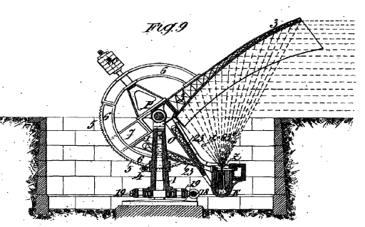
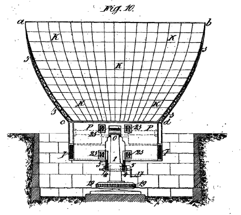
Figures 9 and 10 show in vertical section and elevation respectively, an arrangement permitting as for the sector S3 of Figure 2, a different adjustment of the reflector and affording a focus having certain special movements. The shaft D instead of being placed in the plane of the normal at the centre of the reflector in such a manner. as to form with this normal an angle of about 45 degrees as for the sectors S1 and S2 and in the preceding figures, is situated .in a plane parallel to the respective chord or tangent of each normal arc of the reflecting surface. The point at which this shaft is fixed to the reflector a b c d (Figures 9 and 10) is optional; it may be in a b, or in the middle, or in c d.
So as not. to multiply the figures of the drawings, I have shown an example of only this last (Figures 9 and 10). The shaft D is replaced by a shaft P at the lower part of the reflecting surface and parallel to the chord or to the tangent to the normal arc of this surface, at the level of c drotation around the horizontal axis P still takes place' in a plane parallel to the axis of the solar pencil. In this manner the focus Z and the crucible E in which it is formed must have a parallactic movement, When the sun is oblique and a semi-circular movement around the horizontal axis P and' according to' the plane of the terrestial parallel, when the sun is vertical.
In this last case and to avoid the upsetting of the materials placed in the furnace E or if it be a boiler the entrance of water into the steam chamber, at midday when the sun is at the zenith, I may cause the apparatus to turn a half circumference around the vertical axis 0 and afterwards adjust it only by the movement of vertical rotation around the axis P. This movement is guided by the pillar 1 by means of two guides supporting the two racks 5,5 and it is controlled by means of the pinion 4.
The counterbalances 7 and 20 maintain the equilibrium of the apparatus. The crucible or other device E is supported by means of two frames .or girders 23.
The horizontal rotation around the vertical shaft 0 is obtained in the same way as in the case of Figure 5. In this form of carrying out the invention I have shown a boiler as the apparatus to be: heated.
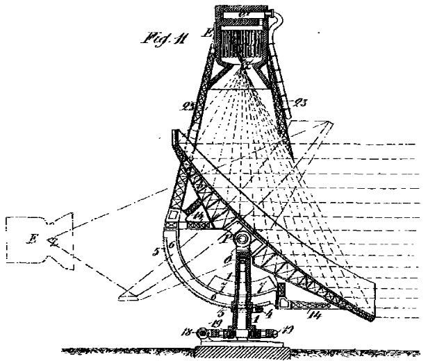
Figure 11 shows in vertical section the frustrum of the paraboloidal sector S$ of Figure 2, mounted and in position for working when the sun is parallel to the horizon.
The horizontal axis P is as in Figures 9 and 10, parallel to the chord or to the tangent of the normal arc of the reflecting surface, but it is placed in the middle of this same surface.
The two rotary movements around the horizontal axis P and around the vertical axis 0 are obtained by the same mechanism as that of Figures 9 and 10.
The focus Z of this arrangement is not easily applicable to metallurgical purposes because the melted materials would fall upon the reflecting surface, but it is applicable to the heating of a boiler such as the arrangement shown in Figures 9 and 10 and can be applied to the production of nitrous acid and other compounds derived from nitrogen which can be obtained by the direct combustion of the nitrogen in the atmosphere by means of the very high temperatures existing in the vicinity of the focus Z.
The nitrous vapours and other compounds of nitrogen resulting from this combustion pass into the chamber e1 whence they may be drawn off from this.
The focus Z is situated in a vertical line when the sun is parallel to the horizon and is horizontal when the sun is in line with the radius of the earth at the point in question.
Figures 12 and 13 show respectively in vertical section on line M-N and horizontal section on line P--Q, (Figure 1) each one of the four paraboloid of revolution frustra S5 S6 S7 S8 of Figure 2, mounted and in the working position, Figure 12 assuming the sun to be vertical and Figure 13 assuming the sun to be parallel with the horizon.
This arrangement of my invention permits of at least two methods of setting or adjusting the apparatus. In the first method) not separately illustrated, the apparatus has only two rotary movements, the one around the vertical shaft 0 and the other oblique (relatively to the radius of the earth at the point in question) around the oblique axis D guided by the collar 24 and operated by means of the circular wheel 25 driven by means of a worm 26.
The focus Z afforded in this example of the apparatus which is hardly or only approximately adjusted by means of these two movements, would not be applicable with facility to purposes other than the heating of a boiler or the combustion of atmospheric nitrogen, like the form of apparatus shown in Figure 11.
But by imparting to it a third movement, the focus Z afforded by this arrangement can be applied to metallurgical and to industrial purposes generally. This third movement is a vertical rotation of the shaft D around the horizontal axis P directed by means of the racks 5.
The rotary movement of the apparatus around the shaft D is obtained by means of a worm 26 engaging the toothed wheel 25. The two other movements are obtained.as in the arrangement shewn in Figures 9 and 10.
In order to set the apparatus, see Figures 11 and 12 the reflecting surface is turned (1) around the axis D, (2) around the axis 0, and (3) around the horizontal axis P, in such a manner that the convergence of the solar rays is ensured at the point Z situated within the crucible E which may remain horizontal, having scarcely a semi-circular rotary movement upon the rails e 2 arranged centrally about the vertical axis 0, whatever be the altitude of the sun above the horizon and in all latitudes.
The crucible E may be furnished with special and corresponding movements upon the truck or car e according to requirements necessitated by the various applications of the invention. it is. to be understood that I may make various modifications in my reflecting system and construction alterations without changing the general idea of my invention and such as arc necessitated by its application to the various branches ot industry. I do not, moreover, limit myself beyond the essentials cited to any strict form of the whole forming the reflecting concavity and its components, nor to any fixed type of framework or girders, supports and' other similar parts nor to any exclusive method, of adjusting the reflecting system, nor to the geometrically perfect curve of a paraboloid of revolution; I may indeed make use of reflectors formed by cutting out one or more sectors in a figure of revolution consisting of a paraboloid or an approximation to a paraboloid.
CH24525 -- Installation pour l'obtention de hautes températures par la chaleur solaire
https://www.utopia500.net/post/2016-1-8-manuel-ant%C3%B3nio-gomes-padre-himalaya
Manuel António Gomes (Padre Himalaya)
Born: 9 December 1868
Died: 21 de December 1933
Nationality: Portuguese
They called him Father Himalaya because he was very tall, and this man, who became known as the Portuguese pioneer of re3newable energies, adopted the nickname with humor. Born in Arcos de Valdevez, he never renounced his rural origins. In fact, it was the search for solutions to the problem of soil fertility that led the priest-scientist to create a solar machine that would soon become known as the Pyrheliophore.
Father Himalaya's adventurous spirit took him to Paris, the United States, South America and the Far East. He experienced ups and downs, depending on the interest he managed to arouse in investors. It was in 1904, at the Saint Louis World’s Fair, that his talent was recognized with the Grand Prize, two gold medals and a silver medal for his Pyrheliophore. Moments of glory followed, with invitations to lectures and visits to scientific institutions, as well as the successful invention of himalaite, a smokeless gunpowder. However, these moments alternated with frequent bouts of discouragement at the lack of interest from investors and the failure of some inventions.
Father Himalaya's utopian spirit was revealed in the exploration of a radically new technological alternative, based on renewable energies and with a strong sense of social transformation. In his lectures, Father Himalaya presented revolutionary ideas in the fields of agriculture, economics, energy policy and seismology which, if put into practice, would radically change the face of the country. His scope for social intervention was also felt in the field of natural treatments, which he studied and promoted in Portugal. Having adhered to vegetarianism, he argued that proper nutrition could pacify human beings and solve economic and public health problems.
https://consolfood.org/wp-content/uploads/2015/12/Ponencia-de-Jean-Jacques-Serra.pdf
LOS HORNOS SOLARES DEL PADRE HIMALAYA
y la reconstrucción del horno solar de Sorede
[ PDF ]
2a generación, 2a versión: Pirhelióforo
Superficie reflectante
Grandes espejos de bronce reemplazados
por 6117 pequeños espejos de vidrio
Tamaño de los espejos: 123 x 98 mm
Distancia media 10 m
Diámetro de la zona focal 15 cm
Crisol: 45 cm de diámetro,
60 cm de profundidad
Recubierto internamente con magnesia