Charles ( Joe ) FLYNN
Parallel Path Magnetic Amplifier
Flynn Research
25409 Timberlake Trail
Greenwood, MO. 64034
(816) 537-5306

rexresearch
Charles ( Joe ) FLYNN
Parallel Path Magnetic Amplifier
Flynn Research
25409 Timberlake Trail
Greenwood, MO. 64034
(816) 537-5306
US6246561
Methods for Controlling the Path of Magnetic Flux from a Permanent Magnet and Devices Incorporating the SameAbstract -- A permanent magnet device includes a permanent magnet having north and south pole faces with a first pole piece positioned adjacent one pole face thereof and a second pole piece positioned adjacent the other pole face thereof so as to create at least two potential magnetic flux paths. A first control coil is positioned along one flux path and a second control coil is positioned along the other flux path, each coil being connected to a control circuit for controlling the energization thereof. The control coils may be energized in a variety of ways to achieved desirable motive and static devices, including linear reciprocating devices, linear motion devices, rotary motion devices and power conversion.
BRIEF DESCRIPTION OF THE INVENTION
For a better understanding of the present invention reference may be made to the accompanying drawings in which:
FIG. 1 is a perspective view of a magnetic device in which the magnetic flux from a magnetic member traverse a single path to produce a coupling force;

FIG. 2 is a perspective view of a magnetic device in which the magnetic flux from a magnetic member splits between two paths;
FIG. 3 is a side view of two magnetic members arrange in parallel between pole pieces;

FIG. 4 is a side view of two magnetic members arranged in series between pole pieces;
FIGS. 5-6 are side views of a permanent magnet device including a permanent magnet having pole pieces positioned against the pole faces thereof and including a movable armature;
FIGS. 7-9 are side views of a permanent magnet device including a permanent magnet having pole pieces positioned against the pole faces thereof to provide two magnetic flux paths and including a movable armature positionable along each magnetic flux path;

FIGS. 10, 10A-10H are perspective views of various embodiments of permanent magnet 5 control components which include two or more magnetic flux paths;
FIGS. 11, 11A-11F are side views of a permanent magnet device including a permanent magnet having pole pieces positioned against the pole faces thereof and including a movable armature and a permanent bypass extending between the pole pieces;
FIGS. 12, 12A-12E are side views of a two path permanent magnet device including two bypasses;
FIGS. 13A-13C are side views of a permanent magnet linear reciprocating device;

FIG. 14 is a side view of an electromagnetic linear reciprocating device;

FIG. 15 is a side view of a two path permanent magnet device showing control coils energized in an exceeding manner;

FIGS. 16A-E are a side view of a linear reciprocating device with control coils energized in an exceeding manner;


FIGS. 17A-17D depict another embodiment of a linear reciprocating device;

FIGS. 18A-18E show a linear motion device;


FIG. 19 is an exploded perspective view of a rotary motion device;

FIG. 20 is a partial assembled and cut away view of the rotary motion device of FIG. 19;

FIGS. 21A-21E are top views of the partial assembly of FIG. 20, which views depict rotational motion thereof,

FIG. 22 is an assembled, cut-away view of the rotary motion device of FIG. 19 including a housing;

FIG. 23 is an exploded perspective view of another embodiment of a rotary motion device;

FIG. 24 is a perspective view of the rotary motion device of FIG. 23 as assembled;

FIGS. 25A-25B are end views of the rotary motion device of FIG. 24 with the end cap removed to expose the rotor member;

FIGS. 26-28 show end views of various configurations for skewing the direction of rotation in the rotary motion device of FIG. 24;
FIGS. 29A-29D are end views of the rotary motion device of FIG. 24 illustrating a sequence of rotational movement thereof;

FIG. 30 is an exploded partial perspective view of another embodiment of a rotary motion device;

FIG. 31 is a perspective view of the rotary motion device of FIG. 30 as assembled
FIGS. 32A-32D are top views of the rotary motion device of FIG. 31 illustrating rotational movement thereof;

FIG. 33 is a side view of the rotary motion device of FIG. 31 as assembled and including a housing;

FIG. 34 is a perspective view of another embodiment of a rotary motion device;

FIG. 35 is a top view of the rotary motion device of FIG. 34;

FIG. 36 is a perspective view of the permanent magnet rotor member of the rotary motion device of FIG. 34;
FIGS. 37 and 38 show alternative configurations for the control component incorporated into the rotary motion device of FIG. 34;

FIGS. 39A-39D are top views of the rotary motion device of FIG. 34 and depict rotational movement thereof;

FIGS. 40-44 are alternative variations of circuit means for controlling the timed energization of control coils in the various devices of the present invention;

FIGS. 45A-45C and 45X-45Z are side views of two path power conversion devices;
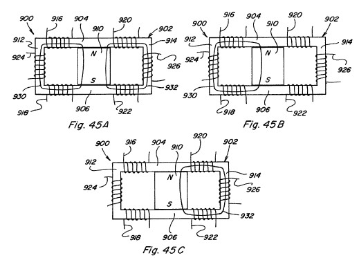

FIG. 46 is a schematic view of the permanent magnet portion of a rotor for use in some embodiments of the present device;

FIGS. 47 and 48 show other embodiments of a linear motion device;
FIG. 49 is a top view of another embodiment of a rotating motor like construction; and

FIG. 50 is a schematic view of one of the three stator portions of the device shown in FIG. 49.
DETAILED DESCRIPTION OF THE DRAWINGS
Referring now to the drawings, FIGS. 1-4 are provided to facilitate an understanding of various aspects or features of the technology utilized in the present invention. FIG. 1 depicts a device 10 having a magnetic flux producing member 12 which may be a permanent magnet or electromagnet with magnetic poles 14 and 16 as shown. Pole pieces 18 and 20 are positioned adjacent respective poles 14 and 16 to provide a path for the magnetic flux of member 12. Each pole piece 18 and 20 includes a respective pole piece end face 22 and 24. As used throughout this specification it is understood that a pole piece, regardless of its shape or size, is preferably formed of soft iron, steel or some other magnetic material, with the preferred material being one which provides low reluctance, exhibits low hysterisis, and has a high magnetic flux density capability. Accordingly, the various pole pieces disclosed and described herein could likewise be of laminate type construction. Referring again to FIG. 1 an armature 26, also formed of magnetic material, is shown with end faces 28 and 30 which are positioned and sized for being placed adjacent pole piece end faces 22 and 24, such that when so positioned a substantially continuous low reluctance path 32 is provided for magnetic flux from north pole 14, through pole piece 18, through armature 26, through pole piece 16, and to south pole 16. The magnetic flux traveling along such path 32 results in a force which tends to hold armature 26 in position adjacent pole piece end faces 22 and 24. The resulting magnetic coupling or holding force F provided between adjacent pole piece end face 22 and armature end face 28, and between adjacent pole piece end face 24 and armature end face 30, can be approximated by the following equation:
where B is the magnetic flux density passing through the adjacent end faces and where A is the surface area of the adjacent end faces. Assuming B uniform throughout flux path 32 and the area A of all end faces 22, 24, 28, and 30 to be the same, the total holding force F.sub.T26 of armature 26 against pole pieces 18 and 20 will be:
In FIG. 2 a device 40 having the same magnetic flux producing member 12 with magnetic poles 14 and 16 is shown. Pole pieces 42 and 44 are positioned adjacent respective pole faces 14 and 16 to provide two paths, as opposed to one above, for the magnetic flux of member 12. In particular, pole piece 42 includes a first path portion 46 extending beyond a perimeter of north pole face 14 in one direction and a second path portion 48 extending beyond the perimeter of north pole face 14 in another direction. Similarly, pole piece 44 includes a first path portion 50 extending beyond the perimeter of south pole face 16 in one direction and a second path portion 52 extending beyond the perimeter of south pole face 16 in another direction. Each pole piece path portion 46, 48, 50, 52 includes a respective end face. A first armature 54 is positionable adjacent the end faces of pole piece path portions 48 and 52 to provide a first magnetic flux path 56 and a second armature 58 is positionable adjacent the end faces of pole piece path portions 46 and 50 to provide a second magnetic flux path 60. If the flux carrying area along flux paths 56 and 60 is the same as the flux carrying area along flux path 32 of FIG. 1, the magnetic flux density along each flux path 56 and 60 will be one-half the magnetic flux density along flux path 32 of FIG. 1 because the same amount of flux is split between two like paths. The effect of dividing a given amount of magnetic flux along two like flux paths instead of along one flux path can be seen by examining the holding force on armature 54 as compared to the holding force on armature 26 of FIG. 1. As already noted the magnetic flux density along path 56 will be one-half that along flux path 32 and thus the total holding force F.sub.T54 can be determined as:
F.sub.T54 =(B/2)2A/,.mu..sub.0 =B.sup.2 A/4.mu..sub.0 =F.sub.T26 /4.
It is therefore seen that dividing the same amount of magnetic flux along two flux paths rather than along one flux path reduces the magnetic holding or coupling force on an armature by one-fourth rather than one-half as might have been expected. This unexpected magnetic holding or coupling force differential, resulting from multiple flux paths, can provide advantageous properties in linear, reciprocating, and rotary motion devices.
Referring now to FIGS. 3-4, the behavior of multiple magnetic flux sources arranged in parallel and series is described as compared to a single flux source. When identical flux sources or magnetic flux producing members 70 and 72 are positioned in parallel as shown in FIG. 3 with pole pieces 74 and 76 positioned adjacent the poles thereof to provide a flux path through armature 78, the flux density B through armature 78 is double what the flux density would be if only one magnetic flux producing member were present. However, the field intensity H resulting from the two members 70 and 72 remains unchanged. This result holds true regardless of whether members 70 and 72 are both permanent magnets, are both electromagnets, or are a combination of one permanent magnet and one electromagnet. On the other hand, the properties resulting from magnetic flux producing members 80 and 82 arranged pole-to-pole in series between pole pieces 84 and 86, with armature 88, as shown in FIG. 4, will vary depending on the nature of the members 80 and 82.
In a first case, if both members 80 and 82 are permanent magnets, the magnetic field intensity H resulting from the two permanent magnets will be double that of one permanent magnet and the flux density B through armature 88 will be the same as what the flux density would be if only one permanent magnet type member were present.
In a second case, if both members 80 and 82 are electromagnets, the field intensity H again doubles and the flux density B increases according to the B/H curve or relationship of the pole piece 84, 86 and armature 88 materials.
In a third case, if member 80 is a permanent magnet and member 82 is an electromagnet, the field intensity H again doubles, but, since the permanent magnet is near flux density saturation B.sub.r the flux density can only be increased from B.sub.r to B.sub.max of the permanent magnet. At the point where electromagnet-type member 82 contacts permanent magnet-type member 80 the flux from the electromagnet-type member 82 couples with the flux of the permanent magnet-type member 82 until the flux density through permanent magnet-type member 80 reaches B.sub.max. At that point additional flux from electromagnet-type member 82 does not contribute to the flux density along the flux path unless a bypass path around the permanent magnet-type member is provided. Use of such bypass paths will be described hereinbelow.
Controlling the flow of flux along both one and multiple flux paths is best described with reference to FIGS. 5-9. In FIGS. 5 and 6 a permanent magnet device 90 including a permanent magnet 92 having pole pieces 94 and 96 positioned adjacent the pole faces thereof and an armature 98 completing a low reluctance path 104 from pole to pole is shown. Control coils 100, 102 are positioned along path 104. When control coils 100, 102 are not energized, the magnetic flux of permanent magnet 92 follows path 104 as shown and armature 98 is held in place against pole pieces 94, 96 due to the resulting magnetic coupling forces. However, if coils 100, 102 are energized to provide an equal but opposing magnetic flux to that of permanent magnet 92, the result is that the magnetic flux of permanent magnet 92 is blocked and no magnetic flux traverses the path which includes armature 98 and therefore no magnetic coupling forces act on armature 98 allowing it to fall away as shown in FIG. 6. The permanent magnet device 90 is useful, although as will become apparent below, it is more advantageous to provide multiple flux paths rather than one.
In this regard, in FIG. 7 a permanent magnet device 110 includes a permanent magnet 112 having pole pieces 114, 116 positioned adjacent the pole faces thereof with armatures 118, 120 completing two low reluctance paths 130, 132 from pole to pole thereof. Control coils 122, 124 are positioned along path 130 and control coils 126, 128 are positioned along path 132. The two paths provided are assumed to be of equal reluctance. With no coils energized, the magnetic flux of permanent magnet 112 divides equally along flux path 130 and along flux path 132 such that both armatures 118, 120 are subjected to a magnetic coupling force which holds them in place against pole pieces 114, 116.
If coils 122, 124 are energized to provide a magnetic flux equal to but opposing the magnetic flux which travels along flux path 130 from permanent magnet 112 when no coils are energized, the result is that the magnetic flux of permanent magnet 112 is blocked and no magnetic flux traverses the path which includes armature 118 and therefore no magnetic coupling forces act on armature 118 allowing it to fall away as shown in FIG. 8. Further, the magnetic flux traversing path 132 will be double that of when no coils are energized and therefore the magnetic coupling force on armature 120 will be about four (4) times that of when no coils are energized. By energizing coils 126, 128 in an opposing manner a similar result would be achieved such that armature 120 would fall away and such that the magnetic coupling force on armature 118 would be increased.
If coils 122, 124 are energized to provide a magnetic flux equal to and aiding the magnetic flux which travels along flux path 130 when no coils are energized, the result is that the control coils couple completely with the magnetic flux of permanent magnet 112 and no magnetic flux traverses the path which includes armature 120 and therefore no magnetic coupling forces act on armature 120 allowing it to fall away as shown in FIG. 9. Further, the magnetic flux traversing path 130 will be double that of when no coils are energized and therefore the magnetic coupling force on armature 118 will be about four (4) times that when no coils are energized. By energizing coils 126, 128 in an aiding manner a similar result would be achieved such that armature 118 would fall away and the magnetic coupling force on armature 120 would be increased.
Based on the foregoing it is seen that the full magnetic coupling force available from the permanent magnet 112 can be switched from one path to another path by the application of one half the power it would require for a coil alone to produce the same magnetic flux along one path. The ability to easily switch the full magnetic coupling force from one path to another allows for efficient reciprocating, linear, and rotary motion and power conversion to be achieved.
The basic device utilized to achieve permanent magnet flux division and to control such permanent magnet flux division is defined herein as a "permanent magnet control component," various configurations of which are shown by way of example only, and not by way of limitation, in FIGS. 10A-10F. FIG. 10A depicts a permanent magnet control component 150 in which pole pieces 152 and 154 are positioned adjacent the pole faces of permanent magnet 156 to provide two magnetic flux paths extending from opposite sides of permanent magnet. Control coils 158 are positioned along each path. FIG. 10B depicts a permanent magnet control component 160 in which pole pieces 162 and 164 are positioned against the pole faces of permanent magnet 166 to provide two spaced, adjacent magnetic flux paths extending from the same side of permanent magnet 166. Control coils 168 are positioned along each path. FIG. 10C depicts a permanent magnet control component 170 in which pole pieces 172 and 174 are configured so as to be positioned adjacent the pole faces of permanent magnet 176 so as to provide four flux paths, each flux path extending in a respective direction from permanent magnet 176. Control coils 178 are also positioned along each path. FIG. 10D depicts another four path configuration of a permanent magnet control component 180 in which pole pieces 182, 184 are configured and positioned to provide four flux paths for permanent magnet 186, with a pair of spaced, adjacent flux paths extending from each side of permanent magnet 186. Control coils 188 are positioned along each path. FIG. 10E depicts another four path configuration of a permanent magnet control component 190 in which all four flux paths formed by pole pieces 192, 194 extend from one side of permanent magnet 196. Again, control coils 198 are positioned along each flux path. FIG. 10F still further depicts a four path configuration of a permanent magnet control component 200 in which pole pieces 202, 204 extend to one side of permanent magnet 206, with pole piece 202 defining four flux paths and with pole piece 204 including a continuous return path. Control coils 208 are positioned along each path of pole piece 202. Many other variations are possible.
Accordingly, it is seen that a variety of different configurations of permanent magnet control components in accordance with the present invention are possible. The important considerations for division of permanent magnet flux in such permanent magnet control components include extending each pole piece to or beyond the outer perimeter of the pole face of the permanent magnet in each region where a flux path is intended and assuring that the pole face of the permanent magnet intersects each of the flux paths. It is not necessary for each pole piece to include the same number of path portions extending beyond the perimeter of the respective permanent magnet pole face as noted with reference to permanent magnet control component 200. Although two control coils are shown along each of the flux paths in FIGS. 10A-10E it is apparent from component 200 in FIG. 10F that one control coil positioned along a flux path is generally sufficient for purposes of the present invention. Further, although in the illustrated configurations each pole piece is positioned to contact a respective pole face of the permanent magnet, a small spacing between a pole piece and its adjacent permanent magnet pole face could be provided, particularly in applications where relative movement between the subject pole piece and the permanent magnet will occur.
In its simplest form a two path permanent magnet control component only requires one control coil positioned along one of the control paths to permit the magnetic flux of a permanent magnet to be switched between the two paths. In particular, a side view of such a two path component 210 is shown in FIG. 10G and includes a permanent magnet 211 pole pieces 212 and 213, and control coil 214 which may be connected to a suitable control circuit. By alternating energizing control coil 214 in an opposing manner and an aiding manner the magnetic flux of permanent magnet can be switched between the path including armature 215 and the path including armature 216. When control coil 214 is energized in an opposing manner the magnetic flux will traverse the path including armature 215 and when control coil 214 is energized in an aiding manner the magnetic flux will traverse the path including armature 216. Control coil 214 could also be placed at anyone of positions 217, 218, or 219 to achieve the flux path switching. Further, in the two coils embodiment shown in FIG. 10H control coil 217 is added. In such a device flux switching can be achieved by simultaneously energizing control coil 214 in a flux aiding manner and control coil 217 in a flux opposing manner, and by then simultaneously reversing the energization of the respective control coils 214 and 217.
Reference is made to FIGS. 11A-11F which depict devices similar to that of FIGS. 5-6 except that a bypass, formed of magnetic material, is provided in each case. In device 220 of FIGS. 11A-11C a bypass 222 is provided from pole piece 224 to pole piece 226 and is located between permanent magnet 228 and control coils 230, 232, with armature 234 located adjacent the ends of pole pieces 224, 226. In FIG. 11A with no coil energization, magnet flux components 236 and 237 travel as shown. When coils 230 and 232 are energized in an aiding or adding manner as in FIG. 11B, the result is permanent magnet magnetic flux components 236 and 237 traveling as shown, and with the added magnetic flux component 238 from coils 230 and 232 also traveling as shown. Thus, in device 220 energizing the coils in an aiding manner results in an increased magnetic coupling force on armature 234. In FIG. 11C coils 230, 232 are energized in an opposing exceeding manner which results in permanent magnetic flux components 236 and 237 traveling as shown and excess magnetic flux component 238 traveling as shown. Thus, in device 220 energizing the coils in an opposing exceeding manner results in magnetic coupling force on armature 234, albeit smaller than that in the aiding exceeding case.
In device 240 of FIGS. 11D-11F a bypass 242 is provided between pole piece 244 and pole piece 246 but is located on an opposite side of permanent magnet 248 as compared to control coils 250, 252 and armature 254. Permanent magnet flux components 256 and 257 are shown for no coil energization in FIG. 11D. In FIG. 11E the paths of permanent magnet flux components 256 and 257, as well as excess coil magnetic flux 258, are shown when coils 250, 252 are energized in an aiding exceeding manner. In FIG. 11F the path of each magnetic flux component 256, 257, and 258 is shown when coils 230, 232 are energized in an opposed exceeding manner.
FIGS. 12A-12E depict a device 270 similar to that shown in FIGS. 7-9 except that bypasses 272 and 274 are provided from pole piece 276 to pole piece 278. Bypass 272 is located between permanent magnet 280 and control coils 282, 284 and bypass 274 is located between permanent magnet 280 and control coils 286, 288. Armatures 290 and 292 are also provided. When no coils are energized permanent magnet magnetic flux components 294, 296, 298, and 300 travel as shown in FIG. 12A.
If coils 282, 284 are energized in an opposing manner permanent magnet flux components 295, 297, and 299 travel as shown, with no flux component traversing the path which includes armature 290 and therefore no magnetic coupling force acting thereon. This would be the case for when coils 282, 284 are energized to the level where the coils magnetic flux just blocks, but does not exceed, the magnetic flux component 294 (FIG. 12A) from permanent magnet 280. If, however, coils 282, 284 are energized in an opposed exceeding manner an excess coil magnetic flux component 301 is produced which travels a path including armature 290 and bypass 272 results as shown in FIG. 12C.
Coils 286, 288 may be energized in an aiding manner such that all permanent magnet magnetic flux travels along the path which includes armature 292 as shown in FIG. 12D. If coils 286, 288 are energized in excess of the level of FIG. 12D then the excess magnetic flux component 304 traverses the path which includes armature 292 and bypass 274 as shown in FIG. 12E, thereby increasing the magnetic coupling force on armature 292 as compared to FIG. 12D. The advantage of incorporating such bypasses into permanent magnet control components in certain applications will become apparent below.
