Gerald ORLOWSKI
Ro-Mag Generator
Ro-Mag Generator
http://jnaudin.free.fr/html/mromag.htm
The Mini-Romag Generator
Design and Drawings by Jean-Louis Naudin
Courtesy of Kevin O. from "Magnetic Energy"
created on 03-19-99 - JLN Labs - last update on 11-15-99
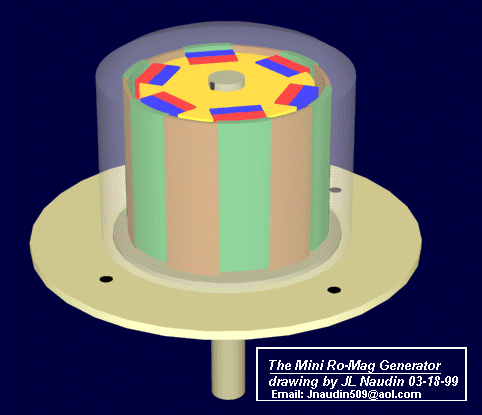
The Mini Romag generator from Magnetic Energy uses the principle of moving magnetic flow named "the magnetic current" for generating electrical power. According to Magnetic Energy this generator is able to produce 3.5 volts, 7A DC ( about 24 Watts ) of free electricity while its generate sufficient power to sustain itself...
This generator need to be started by an external motor during about 42 seconds at 2100 RPM. After this charging process, when the energy flow is established in the Romag generator, the motor can be removed and free electrical energy can be used.
This Romag generator is a new revolutionary concept which generates electrical energy without using the first flow of current generated by magnetism, it uses only the untapped natural resource of the magnetism...
HOW THE UNIT WORKS :
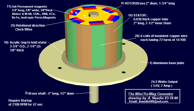
The disclosed 3½ volt, 7 amperage magnet motor/generator must be charged up by driving the main shaft at 2100 RPM for 42 seconds. This charging process manifests as magnetic energy within the six coils of copper wire, the copper tube supporting these coils and the copper coated steel wires wrapped around the magnets. This charging is accomplished while the six coil connection wires, Part #22, are making contact and setting up their alternating magnetic poles. After the 42 second charging time one of these coil connection wires must be opened and this circuit again completed through an energy draw at what could be called 7 amps. See load Part #23. As current is drawn from the six coils, this draw sets up magnetic poles which are a response between the rotor magnets and the coils. This response then causes the main shaft to be rotated by the 12 permanent magnets as they attract and build a release field. Then the driver unit (hand crank) is disconnected allowing the unit to rotate with the load being the activating driving force.
The fields of the magnets must be maintained during their spin movement. These magnetic fields which are encapsulated are achieved by the wiring system. The attract/release of the magnets is a function of several factors. First, the magnets attract field between north and south is completed by taking a crossing path of attract (top of one row to bottom of next, etc.). This action has the effect of fields blending into fields, and a hold—back attract does not happen. Each time a magnet set passes a coil an interchange of like energy between the coils around the magnets and the generating coils sets—up neutral polarities which are ‘release fields’ and prevents a hold—back attract.
One important magnetic assembly is the circuitry which allows this interchange of energy. This is a recycling of a stabilized magnetic/electro energy not electro/magnetic because the field of force is not a case of electrical input, an input that created the magnetic energy, but rather a build—up of magnetic energy which caused an energy thrust.
In further defining the workings of this unit it is important to understand that although electrical and magnetic (energy) work with similar attitudes, the manner in which they work sets—up a differing energy effect. One of these effects is that magnetic structures want to share their f1ow, compatible to the Universal Force, while electrical flow argues, (short circuits, sparks, etc.). Because of this fact the working responses (within the unit) take place, how they are needed, and when they are needed which results in a functioning unit. There is a continuous transmutation process taking place whereby magnetic energy continually generates an energy that manifests a measurable current.
PARTS LIST AND CONSTRUCTION DETAILS
When building your first unit we suggest using the stated materials.
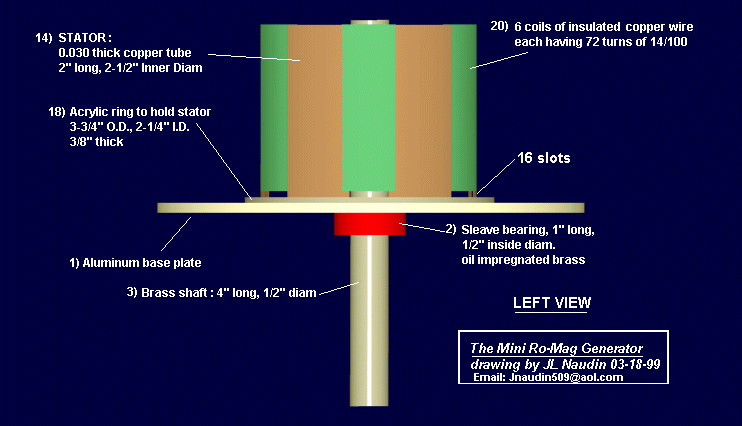
1) Aluminum Base Plate
2) Sleave Bearing, 1" long, ½" inside diameter, oil impregnated brass.
3) 4" long by ½" diameter Brass Shaft
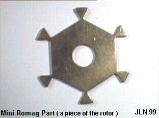
4) Brass 2" diameter Rotor, 1—3/4" long
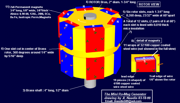
5) Six rotor slots, each 1—3/4" long by .260 deep by 23/32" wide. These slots are spaced exactly 60 degrees apart.
6) One slot cut in center of Brass Rotor, 360 degrees around, ¼" wide by 5/16" deep.
7) 12 slots (formed from the six slots as the 360 degree cut is made). Each slot is lined with .010 thick mica insulation.
8) A total of 228 pieces of U—shaped .040 thick copper coated steel wires. Each slot (Part #7) has 19 pieces of these wires fitted into the Mica, thus these wires do not contact the Brass rotor. The lead edge of these wires is flush with the Rotor’s outer surface and the trail edge protrudes 1/8" above the Rotor’s outer diameter.
9) Eleven complete turns of .032 thick copper coated steel wire. These 11 turns or ‘wraps’ accumulate to 3/8" wide and the same pattern is placed around all 12 magnets. When placed into the bent wires #8, they are a snug fit making firm contact.
10) Are 12 pieces of .005" thick mylar insulation inserted into the cores of the wires #9.
11) 12 permanent magnets, insulated with the mylar, to not contact wires # 9. These magnets measure 3/4" long, 5/8" wide, 3/8" thick and are made of a special composition and strength. Alnico 4, M—60; 12 AL, 28 Ni, 5 Co, bal Fe, Isotropic permanent magnet material cooled in magnetic field, Cast 9100 TS. 450 Brin, 2.2 Peak energy product. When inserted in the rotor the outer faces of these 12 magnets are not to be machined to a radius. The center of these magnets pass the center of the coils with 3/32" clearance. The edges, where the wires are wrapped, pass 1/32" away from the coils. This ‘changing magnet spacing’ aids in not only the release cycle but also contributes to rotational movement. (Sharp magnet edges which are facing the coils are to be sanded to a small smooth radius.)
12) Magnet polarity placement into Rotor.
13) Connection pattern for wires wrapped around magnets. The 12 wire wraps are divided into two sections, upper and lower of six each. There are no connections between these sections. The magnetic flow direction between the upper 6 wraps and the lower 6 wraps is attained by the ‘flow direction’ as shown in Figure 5. Viewing Figure 6 shows the wires wrapped around the magnet starting at the top ‘north’ half and then after 11 complete turns the wire exits at the lower ‘south’ half. As this wire then goes to the next magnet it arrives at an attract wire which is its ‘north’ side. Thus all wires get interconnected from south to north magnet half or north to south magnet half. The actual connections should be crimped copper clips not solder with insulation tubing to prevent contact to the Rotor body.
14) A .030 thick copper tube (stiff material) 2" long by 2½" inside diameter.
15) Are six slots cut at the top of tube #14. These slots are 5/8" wide by 1/32" deep spaced at 60 degrees apart.
16) Are six slots cut at the bottom of tube #14. These slots are 5/8" wide by 5/16" deep and in line with the upper slots #15.
17) Six copper tube mounting points.
18) Acrylic ring to hold Part #14, measuring 3—3/4" O.D., 2¼" I.D., 3/8" thick bolted directly to Part #1. This ring has a .030 wide groove cut ¼"deep to allow the six copper tube mounting points, Part #17, to be inserted.
19) A .002" thick plastic insulation paper to be placed around the inside and outside of Part #14.
20) Are six coils of insulated copper wire, each coil having 72 turns of .014 thick wire. Each coil is wound with two layers, the bottom layer to completely fill the 5/8" wide slot with 45 turns and the top layer to span 5/16" wide with 27 turns. To be sure each coil has the exact wire length or 72 turns, a sample length wire is wrapped then unwound to serve as a template for six lengths. A suggested coil winding method is to fill a small spool with one length then by holding the copper tube at the lower extension, then start at the plus wire in Figure 2 and temporarily secure this wire to the outer surface of the tube. Next, place the pre—measured spool of wire inside the tube, wrapping down and around the outside advancing clockwise until the 5/8" slot is filled with 45 turns. Then, return this wire back across the top of the coil for 15/32" and winding in the same direction again advance clock—wise placing the second layer spanned for 5/16" with 27 turns. This method should have the second layer perfectly centered above the first layer. After winding this coil, repeat the process by again filling the small spool with another length of pre—measured wire. A very important magnetic response happens as all six coils have their second layers spaced as disclosed.
21) This number identifies the top view of the second layer.
22) Connection pattern for six coils. When the unit is driven at start—up (hand crank) for 42 seconds at 2100 RPM, all six jumper wires must be together which means the plus wire goes to the minus wire connected by the start switch. After 42 seconds the load is added to the circuit and the start switch is opened. To double check your connections between the coils, note that the finish wire of coil #1 goes to the finish wire of coil #2, which is top layer to top layer. This pattern then has start of coil 2 (bottom layer) going to start of coil 3 (also bottom layer). When the copper tube with the coils is placed around the rotor, the distance from any magnet to any coil must be identical. If it measures different, acrylic holding shapes can be bolted to the aluminum base, protruding upward, and thus push the copper tube in the direction needed to maintain the spacing as stated.
23) Wires to load.
24) Wires to start switch.
25) Rotational direction which is clock—wise when viewing from top down.
26) Acrylic dome for protection against elements.
27) Coating of clear acrylic to solidify rotor. Do not use standard motor varnish. Pre-heat the rotor and then dip it into heated liquid acrylic. After removal from dip tank, hand rotate until the acrylic hardens, then balance rotor. For balancing procedure, either add brass weights or remove brass as needed by drilling small holes into rotor on its heavy side.
28) Insulation tubing on all connections.
29) Shaft for start purposes and speed testing (if desired).
This concludes the parts list for the Mini-Romag.
This simple unit demonstrates profound concepts and has a surprising number of applications. Remember, it must have a load to work, something that attracts magnetic energy. Build this unit and explore new possibilities with us.
All these informations has been shared freely with courtesy of Magnetic Energy, special thanks to them for sharing their wonderful and advanced technology...
http://jnaudin.free.fr/html/mromexp.htm
The Mini-Romag generator
Towards a possible explanation ?
by Jean-Louis Naudin
The Mini-Romag generator from Magnetic Energy is composed of two main parts : The Rotor and the Stator.
- The Rotor is a brass cylinder with 6 pairs of magnets placed at 60° around its circumference. The magnets polarities are alternatively North and South.
- The Stator is a copper cylinder with 6 flat coils wounded so as the coils axis are tangent to the rotation of the rotor. So, only the orthogonal component of the magnetic field of the magnets is used.
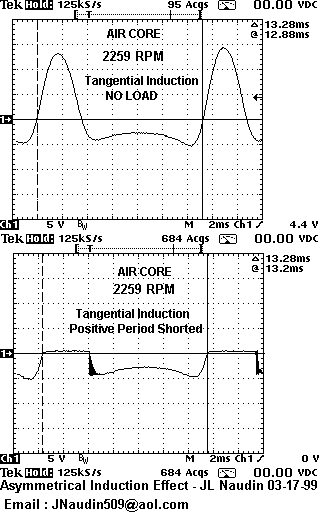
The oscilloscope pictures below, show the signal generated by a moving magnet :
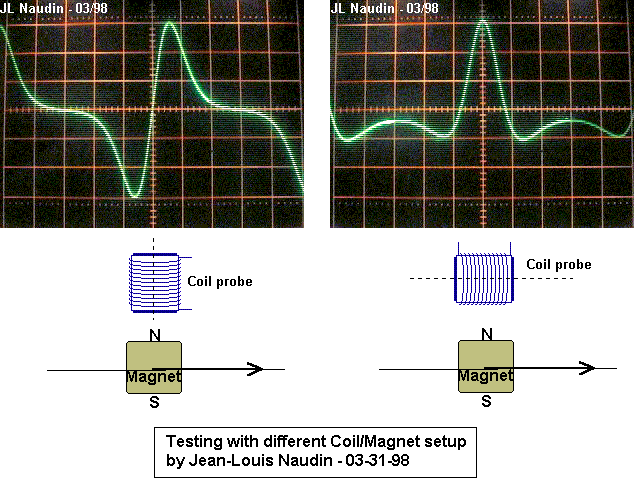
- The left picture is the voltage generated across the coil when a magnet axis crosses the coil axis, this is a conventional setup for a magnetic generator.
- The right picture is the voltage generated across the coil when a magnet axis crosses the middle of the tangent coil (orthogonal component of the magnetic field), this is the case of the Mini-Romag generator.
In the left case (conventional generator), you can notice that the signal induced across the coil is symetrical Vs the zero line, the voltage value induced during the approach phase is equal to the voltage induced during the exit phase. During the approach phase of the North pole of the magnet (from the left to the coil axis), a North pole is created on the bottom surface of the coil (according to the Lenz law), this creates the negative voltage shown. When the North pole of the magnet leaves the axis of the coil, a South pole is created on the bottom surface of the coil (according to the Lenz law), this creates the positive voltage shown in the scope picture. The flux in the coil has been reversed in this case. In this case there is always a magnetic coupling between the rotor (magnets) and the stator (coil).
In the right case (orthogonal field (Mini-Romag Setup)), you may notice that the voltage induced is more positive than negative (asymmetrical) when the magnet crosses the middle of the tangent coil. During the approach phase of the North pole of the magnet (from the left to the middle of the coil), a North pole is created on the left surface of the coil (according to the Lenz law), this creates the negative voltage shown. During the exit phase of the North pole of the magnet (from the middle of the coil to the right), a South pole is created on the right surface of the coil (according to the Lenz law), this creates the negative voltage shown. The coil flux has never been reversed in this case. Now, look at the middle position (when the magnet crosses the middle of the coil). In this case, the orthogonal magnetic flux density drops to zero (this has been checked with a gauss meter). So the positive pulse induced in the coil is not due to the moving magnet, but it is generated by the collapse of the magnetic field (Back EMF)....In this case there is no magnetic coupling between the rotor (magnets) and the stator (coil) during the positive phase of the signal generated.
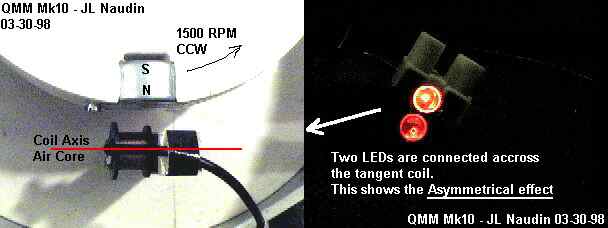
Another test has been conducted by connecting the coil to a power supply (up to 1.37A), I have noticed no significant change in the rotor speed.
So, I have tried to explain only the half part of the Mini-Romag principle, the non-reciprocal effect when the device acts as a generator.
Now, how is the device able to run itself as a motor/generator ?
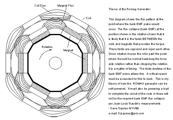
As I have explained previously, there is no magnetic coupling between the rotor (magnets) and the stator (coil) during the positive phase of the signal generated in the tangent coil and also that this positive part of the signal is produced by the collapse of the magnetic field. So, when the current reaches its maximum value the magnet is placed just in front of the middle of the coil. This is the case for all the coils/magnets (from 1 to 6). The wires have been connected so as all the Back EMF voltages are added (see the picture below).
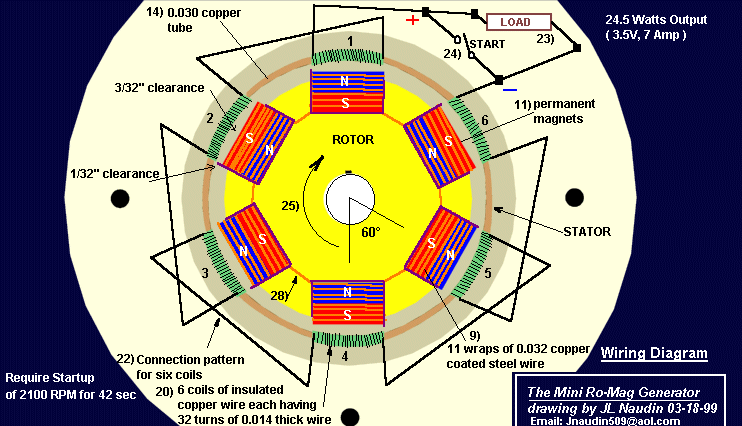
At this moment, we have two important events : the Back EMF current is maximum and the creation of a magnetic field in the coil which contributes to ATTRACT the previous magnet placed at -60°.
For instance :
- the coil #1 attracts the coil magnet #2,
- the coil #2 attracts the coil magnet #3,
- the coil #3 attracts the coil magnet #4,
- the coil #4 attracts the coil magnet #5,
- the coil #5 attracts the coil magnet #6,
- the coil #6 attracts the coil magnet #1.
According to this principle, it seems possible that the Mini-Romag is able to generate its own motional energy at a certain speed and thus, is able to run itself in self-sustained mode....
The use of a copper tube for the stator contributes to increase the attraction of the previous rotor magnet, because the eddy currents induced change their magnetic axis direction due to the magnetic field interaction with the magnetic field generated in the stator coil.
This is a personal analysis, and this proposal needs to be checked experimentaly, so, today, I can't confirm that this device can work really as Magnetic Energy claims, but some premises encourage me to go further in this way...
You will find below some additional informations sent by Magnetic Energy about the "Magnetic Current"...
Very briefly, magnetic current is an energy that can flow through a wire, it can jump a gap and change form, it can be conducted through air and space, it can take on an infinite variety of polarities, it will not shock the body but make it numb depending on the intensity (more on this later), it flows when it is attracted to something, it can produce matter or break down matter in the right conditions, it can produce force fields, it can assist in momentum, it can assist in particle detection up close or far away, it can produce heat and cold in the right conditions, it can produce light in the right conditions, it can effect any natural system either enhancing it or alleviating it, it can enhance or detract from literally any energy form, it can be polarized into fields that can serve an infinite number of purposes, it does not deplete the earth's atmosphere like electricity, it occurs in various levels throughout nature, it can be monitored like electricity but it is not the same, nature does not produce electricity - it produces magnetic current that can be measured as electricity, magnetic current can move at a nearly infinite velocity, and it can be altered by the elements it interacts with - this is why the composition of the magnets is so very important - the composition or the elements determine the characteristics of the magnetic current as well as its speed and pulse rate. Every amazing or miraculous human event can be reproduced using magnetic current in the right conditions.>>
Recommended documents:
"Magnetic Currents -- the Monopole ?" by Kristen Joseph (Electric Spacecraft Journal July/Aug/sept 1991) Issue No.3
"New experiments about the Magnetic Current", Ehrenhaft, Felix, Physical Review, Vol 65, 1944, pp 62-63
"Continuation of experiments with the Magnetic Current", Ehrenhaft, Felix, Physical Review, Vol 65, 1944, pp 256
"Magnetic Current" Radio News Electric World, April 1945, p22.
http://jnaudin.free.fr/html/dsqromag.htm
The Mini-Romag generator
Theory of the Romag Generator
by Dave Squires